EP1227235A1 - Method for controlling an engine - Google Patents
Method for controlling an engine Download PDFInfo
- Publication number
- EP1227235A1 EP1227235A1 EP02001831A EP02001831A EP1227235A1 EP 1227235 A1 EP1227235 A1 EP 1227235A1 EP 02001831 A EP02001831 A EP 02001831A EP 02001831 A EP02001831 A EP 02001831A EP 1227235 A1 EP1227235 A1 EP 1227235A1
- Authority
- EP
- European Patent Office
- Prior art keywords
- torque
- determining
- acceleration variation
- actuator
- correction value
- Prior art date
- Legal status (The legal status is an assumption and is not a legal conclusion. Google has not performed a legal analysis and makes no representation as to the accuracy of the status listed.)
- Granted
Links
- 238000000034 method Methods 0.000 title claims abstract description 39
- 238000012937 correction Methods 0.000 claims abstract description 57
- 230000004075 alteration Effects 0.000 claims abstract description 17
- 238000012545 processing Methods 0.000 claims abstract description 5
- 230000001133 acceleration Effects 0.000 claims description 85
- 230000008859 change Effects 0.000 claims description 75
- 230000007704 transition Effects 0.000 claims description 38
- 238000002485 combustion reaction Methods 0.000 claims description 18
- 230000009849 deactivation Effects 0.000 claims description 5
- 238000002347 injection Methods 0.000 claims description 4
- 239000007924 injection Substances 0.000 claims description 4
- 238000005070 sampling Methods 0.000 description 6
- 230000001934 delay Effects 0.000 description 4
- 239000000446 fuel Substances 0.000 description 4
- 239000003054 catalyst Substances 0.000 description 3
- 230000008929 regeneration Effects 0.000 description 3
- 238000011069 regeneration method Methods 0.000 description 3
- 230000004044 response Effects 0.000 description 3
- 230000032683 aging Effects 0.000 description 2
- 230000005540 biological transmission Effects 0.000 description 2
- 238000004364 calculation method Methods 0.000 description 2
- 230000006866 deterioration Effects 0.000 description 2
- 230000008569 process Effects 0.000 description 2
- 101150027068 DEGS1 gene Proteins 0.000 description 1
- 230000003044 adaptive effect Effects 0.000 description 1
- 238000004378 air conditioning Methods 0.000 description 1
- 238000013459 approach Methods 0.000 description 1
- 238000006243 chemical reaction Methods 0.000 description 1
- 238000001514 detection method Methods 0.000 description 1
- 230000000694 effects Effects 0.000 description 1
- 238000004519 manufacturing process Methods 0.000 description 1
- 238000005259 measurement Methods 0.000 description 1
- 230000008447 perception Effects 0.000 description 1
- 230000009467 reduction Effects 0.000 description 1
Images

Classifications
-
- F—MECHANICAL ENGINEERING; LIGHTING; HEATING; WEAPONS; BLASTING
- F02—COMBUSTION ENGINES; HOT-GAS OR COMBUSTION-PRODUCT ENGINE PLANTS
- F02P—IGNITION, OTHER THAN COMPRESSION IGNITION, FOR INTERNAL-COMBUSTION ENGINES; TESTING OF IGNITION TIMING IN COMPRESSION-IGNITION ENGINES
- F02P5/00—Advancing or retarding ignition; Control therefor
- F02P5/04—Advancing or retarding ignition; Control therefor automatically, as a function of the working conditions of the engine or vehicle or of the atmospheric conditions
- F02P5/045—Advancing or retarding ignition; Control therefor automatically, as a function of the working conditions of the engine or vehicle or of the atmospheric conditions combined with electronic control of other engine functions, e.g. fuel injection
-
- F—MECHANICAL ENGINEERING; LIGHTING; HEATING; WEAPONS; BLASTING
- F02—COMBUSTION ENGINES; HOT-GAS OR COMBUSTION-PRODUCT ENGINE PLANTS
- F02D—CONTROLLING COMBUSTION ENGINES
- F02D37/00—Non-electrical conjoint control of two or more functions of engines, not otherwise provided for
- F02D37/02—Non-electrical conjoint control of two or more functions of engines, not otherwise provided for one of the functions being ignition
-
- F—MECHANICAL ENGINEERING; LIGHTING; HEATING; WEAPONS; BLASTING
- F02—COMBUSTION ENGINES; HOT-GAS OR COMBUSTION-PRODUCT ENGINE PLANTS
- F02D—CONTROLLING COMBUSTION ENGINES
- F02D41/00—Electrical control of supply of combustible mixture or its constituents
- F02D41/02—Circuit arrangements for generating control signals
- F02D41/14—Introducing closed-loop corrections
- F02D41/1497—With detection of the mechanical response of the engine
-
- F—MECHANICAL ENGINEERING; LIGHTING; HEATING; WEAPONS; BLASTING
- F02—COMBUSTION ENGINES; HOT-GAS OR COMBUSTION-PRODUCT ENGINE PLANTS
- F02D—CONTROLLING COMBUSTION ENGINES
- F02D41/00—Electrical control of supply of combustible mixture or its constituents
- F02D41/30—Controlling fuel injection
- F02D41/3011—Controlling fuel injection according to or using specific or several modes of combustion
- F02D41/3064—Controlling fuel injection according to or using specific or several modes of combustion with special control during transition between modes
- F02D41/307—Controlling fuel injection according to or using specific or several modes of combustion with special control during transition between modes to avoid torque shocks
-
- F—MECHANICAL ENGINEERING; LIGHTING; HEATING; WEAPONS; BLASTING
- F02—COMBUSTION ENGINES; HOT-GAS OR COMBUSTION-PRODUCT ENGINE PLANTS
- F02D—CONTROLLING COMBUSTION ENGINES
- F02D2200/00—Input parameters for engine control
- F02D2200/02—Input parameters for engine control the parameters being related to the engine
- F02D2200/10—Parameters related to the engine output, e.g. engine torque or engine speed
- F02D2200/1002—Output torque
- F02D2200/1004—Estimation of the output torque
-
- F—MECHANICAL ENGINEERING; LIGHTING; HEATING; WEAPONS; BLASTING
- F02—COMBUSTION ENGINES; HOT-GAS OR COMBUSTION-PRODUCT ENGINE PLANTS
- F02D—CONTROLLING COMBUSTION ENGINES
- F02D2200/00—Input parameters for engine control
- F02D2200/02—Input parameters for engine control the parameters being related to the engine
- F02D2200/10—Parameters related to the engine output, e.g. engine torque or engine speed
- F02D2200/1012—Engine speed gradient
-
- F—MECHANICAL ENGINEERING; LIGHTING; HEATING; WEAPONS; BLASTING
- F02—COMBUSTION ENGINES; HOT-GAS OR COMBUSTION-PRODUCT ENGINE PLANTS
- F02D—CONTROLLING COMBUSTION ENGINES
- F02D2250/00—Engine control related to specific problems or objectives
- F02D2250/18—Control of the engine output torque
Definitions
- the present invention relates to a method for controlling an engine, and more specifically a method for controlling non-requested torque changes in an engine.
- Direct injection gasoline engines have become commercially available in recent years and are projected to form an increasingly important segment in the automotive powertrain market in Europe and in Japan.
- DIG engines generally operate with a number of combustion modes other than the homogeneous stoichiometric/rich mode used by traditional multiple port fuel injection (MPFI) engines. These additional modes will include stratified lean and homogeneous lean modes. Switching between the different modes will generally occur in response to different driver torque requests (more desired torque might mean switching from homogeneous lean to homogeneous rich mode). These torque requests might be defined in terms of acceleration in some systems.
- MPFI multiple port fuel injection
- the combustion mode is based on a variety of other engine condition criteria such as the need for NOx regeneration or catalyst protection. Consequently, the combustion mode with which the DIG engine is operating may change frequently throughout a drive cycle, even if no change in torque is requested by the driver. The driver will not wish to feel a change in torque during these mode-switching periods. Furthermore, in view of component durability, fuel economy and emission requirements, each abrupt torque change is of course potentially undesirable. Accordingly, there is a need for controlling the engine to ensure as smooth a transition between combustion modes as possible, so that each abrupt torque change is prevented.
- the control of the engine is generally achieved through the use of look-up tables, e.g. spark timing maps or fuelling maps, with desired torque as an input, in order to determine actuator settings for the new combustion mode.
- look-up tables e.g. spark timing maps or fuelling maps
- the transition strategies generally do not actively control the torque during and/or immediately after a transition. Consequently, there exists a risk that the transition may not always be smooth. Should there be a deterioration in the relative quality of the look-up tables utilised for the mode transmission, e.g. as a result of plant ageing, a torque mismatch between combustion modes will occur and a smooth transition will no longer take place.
- the object of the present invention is to provide an improved method for controlling an engine.
- the present invention generally proposes a method for controlling torque aberrations of an engine, wherein said engine comprises at least one actuator for controlling engine management, which comprises the steps of
- a torque aberration can therefore be defined as follows: i.e. the torque aberration ( ⁇ T ) is linearly related to an acceleration aberration ( ⁇ ). It follows that by determining a correction value based on actual acceleration variation, a torque aberration can be effectively corrected.
- Such an algorithm based upon engine speed is particularly apt because of the fact that it is the change in engine/vehicle speed that is actually noticed by the occupants of the vehicle and is directly responsible for any perception of transition roughness. This equation also demonstrates that such an method is applicable to control systems where driver commands are expressed in terms of acceleration as well as in terms of torque.
- the method of the present invention represents a closed loop correction algorithm, which actively considers the actual situation in order to correct torque aberrations. Furthermore, this correction is based on readily available data in current engines. In fact, in existing engine control software, a time value is recorded every time the flywheel is at a specific angular position. In some software, mainly relating to 4 cylinder engines, this might e.g. be every time the flywheel rotates through 180 degrees. From these time values, a velocity (averaged over the 180-degree sampling period) is calculated. The algorithm can therefore take these time data used to calculate velocity in addition to the results of the pre-existing velocity calculation. The algorithm being based on a detection of flywheel speed acceleration variation, no sensing of absolute torque values and accordingly no torque sensors are required. This algorithm is therefore useful on the current generation of systems that are currently being developed without torque estimators or sensors. The algorithm uses only current sensors and therefore not requires the implementation of any additional hardware.
- the output of the algorithm is fed into an existing actuator for controlling engine management.
- the actuator can e.g. comprise an engine control unit for controlling spark timing and/or fuelling and/or air intake and/or exhaust gas recirculation and/or port deactivation. It follows that the method of the present invention does not rely on hardware other than that already present in current engines.
- the method according to the present invention is particularly suitable for controlling torque aberrations due to combustion mode transitions in a direct gasoline injection engine.
- a transition status flag indicative of the occurrence of a combustion mode transition is preferably set and the actuator correction value is determined and fed into an actuator controller of the engine at least if said transition status flag is set.
- a sudden drop or increase in torque due to the introduction of a new combustion mode would cause an acceleration or deceleration of flywheel speed. This might then be used to introduce a change in fuelling (DIG being fuel lead control in most cases) or spark in order to rapidly compensate the torque.
- DIG being fuel lead control in most cases
- a potential problem with respect to the implementation of such an algorithm would be the consideration of torque changes during a combustion mode transition that are not associated with the mode switch itself. Such torque changes might be caused by an increase/decrease in desired torque for purposes of vehicle acceleration/deceleration, changes in road gradient/surface and vehicle drag, or gearshifts. These torque changes would also affect engine speed, and therefore their effects upon flywheel speed would have to be taken into account by the algorithm.
- a change in demanded torque will therefore be considered.
- a change in demanded torque ⁇ T dem is determined and a demanded acceleration variation ⁇ dem is calculated based on the change in demanded torque.
- the actuator correction value will be determined based on said undesired acceleration variation.
- the demanded parameter may already be defined in terms of acceleration. It should be clear that in such a case a torque to acceleration conversion is not necessary.
- a variation of acceleration ⁇ load of said engine prior to the setting of said transition status flag can further be determined, said variation being indicative of a change in engine load, and a load based acceleration variation calculated.
- the actuator correction value will be determined based on said undesired acceleration variation.
- said actuator correction value is therefore stored and said stored correction value is used for controlling torque aberration if said combustion mode transition is reversed.
- the magnitude of torque discrepancy due to transition from one mode to another may be indicative of the torque discrepancy that may occur when the mode switch is reversed. This is providing that the switching to and from modes occur relatively close to one another in time, e.g. during Nox regeneration transitioning with respect to a lean Nox catalyst.
- look-up tables or the like can be used to provide different actuator correction values for different engine conditions. These tables should preferably be adaptive in order to provide some learn capability over time. This would also allow for deterioration in the relative quality of the look-up tables utilised for the mode transmission, e.g. as a result of plant ageing.
- a brake applied flag may be set when vehicle brakes are commanded and the actuator correction value is determined and fed into an actuator controller of the engine only if said brake applied flag is not set.
- the determination of the actuator correction value is preferably executed by means of a PID controller or a PI controller or a derivative thereof.
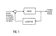
- flywheel speed for correction of engine torque is essentially a feedback technique and may be represented in its most basic form as shown in fig.1.
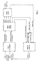
- Fig.2 outlines the basic architecture of the control algorithm.
- the algorithm is basically made out of the following components:
- the problem may be approximated to a 'parameter uncertainty' problem.
- integral control is often utilised as a method of correction.
- the principal control technique utilised is that of a PID or a PI controller.
- the input to this PID controller is the error between the desired signal and the actual signal.
- This error signal could easily have been the torque signal, if the respective acceleration values were multiplied by an engine inertia term J eng according to eq.2. However, they may be maintained as acceleration term and the constant J eng can effectively be combined with the PID proportional gain constant, K p .
- the magnitude of torque discrepancy due to transition from one mode to another may be indicative of the torque discrepancy that may occur when the mode switch is reversed. This is providing that the switching to and from modes occur relatively close to one another in time, e.g. during Nox regeneration transitioning with respect to a lean Nox catalyst.
- Such feed forward compensation is included in the algorithm. Only half of the magnitude of the first torque peak is applied for reasons of conservatism - in case the transition reversal torque is different. The feed forward compensation is of course also applied in the opposite direction to the initial torque peak.
- the preliminary block for the algorithm is in fact the data process and sampling block. Into this block enter the flywheel data samples. Ultimately the commanded torque from the engine control unit ECU will also enter.
- commanded torque signals would have to have any torque correction component removed from them in order to prevent the controller 'correcting for a correction' in commanded torque.
- Changes in load torque are far harder to account for. This is because they are not easily determined outputs of an ECU but are in fact determined by changes in external factors such as wind resistance and road gradient etc.
- the rate of change in load torque is determined before control is applied. This is done by finding the average change in flywheel acceleration (proportional to rate of change in torque according to eq.2), for example over a period of 150 sampling periods. Such a period is required in order to filter out instantaneous fluctuations. However it still remains relatively short in time terms (engine speed being in the order of thousands of rpm) and load torque changes, being due to physical conditions, should not change too rapidly.
- rate of change of load torque prior to control is obtained. This value is then integrated throughout the period of control via a discrete integrator. It should be noted that this method does not take into account changes in load torque during control (unlike the commanded torque consideration). This is not possible to determine because torque changes due to transition and load torque cannot be separately identified.
- the transition corrector algorithm can be designed to be compatible with a torque based control software as show in fig.3.
- a torque based control software as show in fig.3.
- Such software essentially consists of a torque controller that is used to determine engine actuator settings such as spark timing, throttle position, external EGR rate and amount of fuel injected. The determination of such actuator settings are based upon inputs of desired indicated torque - an ordinary torque and extraordinary torque input.
- the extraordinary torque represents special torque requests, such as those from a traction control system or during idle, when non-optimum torque conditions are required. These non-optimum conditions may be quickly obtained through spark control.
- the described input parameters are only given as an example. Other forms of architecture are possible and compatible with the algorithm.
- torque inputs are calculated e.g. within the torque co-ordinator where torques from various sources are combined in order to provide the torque inputs to the controller.
- sources include driver pedal position, air-conditioning, traction control etc. It is appropriate to include the output of the transition corrector algorithm amongst them. In order to do so, the output of the algorithm must be defined as a torque value.
- the torque co-ordinator will then be responsible for deciding whether the torque correction takes the form of an extra-ordinary torque request or whether it should be fed into a torque controller as a corrected ordinary torque request. Negative torque corrections may well be best applied via extra-ordinary torque. Positive torque requests, when spark is already at optimum, would not be suited to spark control and would have to be achieved via correction of ordinary torque.
- a number of inputs to the algorithm are required. Foremost of these inputs is the data related to the flywheel.
- a time value is recorded every time the flywheel rotates through 180 degrees. From these time values, a velocity (averaged over the 180 degree sampling period) is calculated. The algorithm would therefore take this time data used to calculate velocity in addition to the results of the pre-existing velocity calculation.
- Other data can include a transition status flag in order for the algorithm to recognise when a transition begins and ends. Additionally a similar flag representing brake applied can be fed into the algorithm in order to disable it when braking is required. This ensures that breaking is always applied as effectively as possible.
- the controller sets engine actuators in direct response to a commanded desired torque input
- the resultant actual torque delivered by the engine at a given instant will not always correspond to the commanded torque.
- the value of this actual torque is calculated within the torque controller and is also delivered as an input to the algorithm. This is in order for compensation of the transition torque correction value when changes in commanded torque occur during the transition.
Landscapes
- Engineering & Computer Science (AREA)
- Chemical & Material Sciences (AREA)
- Combustion & Propulsion (AREA)
- Mechanical Engineering (AREA)
- General Engineering & Computer Science (AREA)
- Combined Controls Of Internal Combustion Engines (AREA)
- Electrical Control Of Air Or Fuel Supplied To Internal-Combustion Engine (AREA)
Abstract
Description
- The present invention relates to a method for controlling an engine, and more specifically a method for controlling non-requested torque changes in an engine.
- Direct injection gasoline engines (DIG) have become commercially available in recent years and are projected to form an increasingly important segment in the automotive powertrain market in Europe and in Japan.
- DIG engines generally operate with a number of combustion modes other than the homogeneous stoichiometric/rich mode used by traditional multiple port fuel injection (MPFI) engines. These additional modes will include stratified lean and homogeneous lean modes. Switching between the different modes will generally occur in response to different driver torque requests (more desired torque might mean switching from homogeneous lean to homogeneous rich mode). These torque requests might be defined in terms of acceleration in some systems.
- In addition to this load-speed considerations, the combustion mode is based on a variety of other engine condition criteria such as the need for NOx regeneration or catalyst protection. Consequently, the combustion mode with which the DIG engine is operating may change frequently throughout a drive cycle, even if no change in torque is requested by the driver. The driver will not wish to feel a change in torque during these mode-switching periods. Furthermore, in view of component durability, fuel economy and emission requirements, each abrupt torque change is of course potentially undesirable. Accordingly, there is a need for controlling the engine to ensure as smooth a transition between combustion modes as possible, so that each abrupt torque change is prevented.
- In order for high quality driveability to be maintained, it is important that torque aberrations resulting from mode switching are minimised. In order for these to be controlled, some form of measurement of torque would be required. An obvious means for doing this would be the use of a torque sensor. Such a sensor would be able to provide absolute values of torque. However, these torque sensors are very expensive and very heavy.
- Consequently the control of the engine is generally achieved through the use of look-up tables, e.g. spark timing maps or fuelling maps, with desired torque as an input, in order to determine actuator settings for the new combustion mode. The transition strategies generally do not actively control the torque during and/or immediately after a transition. Consequently, there exists a risk that the transition may not always be smooth. Should there be a deterioration in the relative quality of the look-up tables utilised for the mode transmission, e.g. as a result of plant ageing, a torque mismatch between combustion modes will occur and a smooth transition will no longer take place.
- The object of the present invention is to provide an improved method for controlling an engine.
- In order to overcome the above-mentioned problem, the present invention generally proposes a method for controlling torque aberrations of an engine, wherein said engine comprises at least one actuator for controlling engine management, which comprises the steps of
- a) recording rotating speed data of said engine,
- b) processing said rotating speed data for detecting a variation of acceleration of said engine and calculating an actual acceleration variation,
- c) determining an actuator correction value from said actual acceleration variation,
- d) feeding said actuator correction value into an actuator controller of said actuator.
-
- The method of the present invention is based on the fact, that torque and rotating speed of an engine are related by the following simple relationship T = J × ω, where T represents net torque, J represents rotational inertia andrepresents angular acceleration. A torque aberration can therefore be defined as follows:
 i.e. the torque aberration (ΔT) is linearly related to an acceleration aberration (Δ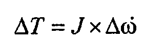
- Thus, the method of the present invention represents a closed loop correction algorithm, which actively considers the actual situation in order to correct torque aberrations. Furthermore, this correction is based on readily available data in current engines. In fact, in existing engine control software, a time value is recorded every time the flywheel is at a specific angular position. In some software, mainly relating to 4 cylinder engines, this might e.g. be every time the flywheel rotates through 180 degrees. From these time values, a velocity (averaged over the 180-degree sampling period) is calculated. The algorithm can therefore take these time data used to calculate velocity in addition to the results of the pre-existing velocity calculation. The algorithm being based on a detection of flywheel speed acceleration variation, no sensing of absolute torque values and accordingly no torque sensors are required. This algorithm is therefore useful on the current generation of systems that are currently being developed without torque estimators or sensors. The algorithm uses only current sensors and therefore not requires the implementation of any additional hardware.
- Furthermore, the output of the algorithm is fed into an existing actuator for controlling engine management. The actuator can e.g. comprise an engine control unit for controlling spark timing and/or fuelling and/or air intake and/or exhaust gas recirculation and/or port deactivation. It follows that the method of the present invention does not rely on hardware other than that already present in current engines.
- The method according to the present invention is particularly suitable for controlling torque aberrations due to combustion mode transitions in a direct gasoline injection engine. In this case, a transition status flag indicative of the occurrence of a combustion mode transition is preferably set and the actuator correction value is determined and fed into an actuator controller of the engine at least if said transition status flag is set. A sudden drop or increase in torque due to the introduction of a new combustion mode would cause an acceleration or deceleration of flywheel speed. This might then be used to introduce a change in fuelling (DIG being fuel lead control in most cases) or spark in order to rapidly compensate the torque.
- A potential problem with respect to the implementation of such an algorithm would be the consideration of torque changes during a combustion mode transition that are not associated with the mode switch itself. Such torque changes might be caused by an increase/decrease in desired torque for purposes of vehicle acceleration/deceleration, changes in road gradient/surface and vehicle drag, or gearshifts. These torque changes would also affect engine speed, and therefore their effects upon flywheel speed would have to be taken into account by the algorithm.
- In a more preferred embodiment of the method, a change in demanded torque will therefore be considered. In this case, a change in demanded torque ΔTdem is determined and a demanded acceleration variation Δ
- In order to also compensate torque changes due to engine load, a variation of acceleration Δ
- In an alternative embodiment, the acceleration variation can be converted into an actual torque change value ΔTact using the relationship ΔT = J × Δ
- One potential flaw in the overall strategy of utilising change in flywheel speed in order to facilitate smooth transition between combustion modes is that the algorithm will only operate once a speed change, implying a torque change, has already been detected. It could therefore be desirable for the algorithm to correct for torque before the changes become perceptible to the driver. In a preferred embodiment of the method, said actuator correction value is therefore stored and said stored correction value is used for controlling torque aberration if said combustion mode transition is reversed. The magnitude of torque discrepancy due to transition from one mode to another may be indicative of the torque discrepancy that may occur when the mode switch is reversed. This is providing that the switching to and from modes occur relatively close to one another in time, e.g. during Nox regeneration transitioning with respect to a lean Nox catalyst. Furthermore, look-up tables or the like can be used to provide different actuator correction values for different engine conditions. These tables should preferably be adaptive in order to provide some learn capability over time. This would also allow for deterioration in the relative quality of the look-up tables utilised for the mode transmission, e.g. as a result of plant ageing.
- In order to disable the torque correction when the brakes of the vehicle are applied, a brake applied flag may be set when vehicle brakes are commanded and the actuator correction value is determined and fed into an actuator controller of the engine only if said brake applied flag is not set.
- It has to be noted, that the determination of the actuator correction value is preferably executed by means of a PID controller or a PI controller or a derivative thereof.
- It should further be noted that, in addition to DIG, the algorithm of the present invention could also be applicable within the context of cylinder deactivation. This is because cylinder deactivation could also lead to abrupt torque changes as well.
- The present invention will be more apparent from the following description of a not limiting embodiment with reference to the attached drawings, wherein
- Fig.1: a fundamental representation of the control algorithm;
- Fig.2: the base algorithm architecture; and
- Fig.3: the position of the algorithm within the overall control software.
-
- The utilisation of the flywheel speed for correction of engine torque is essentially a feedback technique and may be represented in its most basic form as shown in fig.1.
- The algorithm might be considered to be a type of state estimator. This is true in as much as that a measured state (engine speed) is used to estimate a torque change, i.e. an engine state that cannot be measured on current production vehicles. Torque and speed are related by the following simple relationship T = J ×
- It is clear from eq.2 that two flywheel speed samples must be taken in order to obtain one value of flywheel acceleration. In order to identify an acceleration aberration comparison must be made with respect to previous values. Additionally, the algorithm also has to take into account that a change in acceleration may well be occurring independently, but simultaneously with a mode change. This may either be as a consequence of a change in load torque or a change in actual torque commanded by the engine controller.
- Fig.2 outlines the basic architecture of the control algorithm. The algorithm is basically made out of the following components:
- With respect to particular control techniques, the problem may be approximated to a 'parameter uncertainty' problem. In such cases, integral control is often utilised as a method of correction. As a consequence the principal control technique utilised is that of a PID or a PI controller. The input to this PID controller is the error between the desired signal and the actual signal. This error signal could easily have been the torque signal, if the respective acceleration values were multiplied by an engine inertia term Jeng according to eq.2. However, they may be maintained as acceleration term and the constant Jeng can effectively be combined with the PID proportional gain constant, Kp. This can be done because the value of Kp would have to be tuned and the combination of Kp and Jeng would eradicate any requirement for the calibrator to know the value of Jeng if the algorithm is to be used in steady state operation. Nonetheless, if it is to be used during non-steady state conditions, the constant Jeng must be used elsewhere anyway.
- The magnitude of torque discrepancy due to transition from one mode to another may be indicative of the torque discrepancy that may occur when the mode switch is reversed. This is providing that the switching to and from modes occur relatively close to one another in time, e.g. during Nox regeneration transitioning with respect to a lean Nox catalyst. Such feed forward compensation is included in the algorithm. Only half of the magnitude of the first torque peak is applied for reasons of conservatism - in case the transition reversal torque is different. The feed forward compensation is of course also applied in the opposite direction to the initial torque peak.
- The preliminary block for the algorithm is in fact the data process and sampling block. Into this block enter the flywheel data samples. Ultimately the commanded torque from the engine control unit ECU will also enter.
- The outputs from this block are:
- i) Time Interval - the sampling period is in CA degs and therefore varies in time depending upon engine speed. This output is used in determining the rate of change in commanded torque.
- ii) Velocity - used for determining combustion delays.
- iii) Flywheel acceleration.
- iv) Rate of delta torque change - with no transition occurring. This is for use in applying control under non-steady state conditions.
-
- Under steady state torque conditions control is relatively easy because the controller simply has to maintain the torque at the value corresponding to the situation just before transition. However, such an approach is clearly not appropriate when that torque value has been in the process of change prior to the transition. Indeed it is also not appropriate if that torque value were to change during the period during which control is applied as a consequence of factors unrelated to the transition. Such factors that contribute to changes in torque, unrelated to transitions, consist of changes in load torque and changes in commanded torque. Their changes are taken into account by the algorithm, as may be seen in fig.2, by subtracting their respective changes during the control period from the error value fed into the PID controller.
- It should be noted that any changes in commanded torque have to be passed through a delay corresponding to a combustion delay before they are applied to the error. It is also worth noting that depending on the actual algorithm structure the error may be an acceleration term. In this case the value Jeng has to be used to convert it into an acceleration value before application to the error signal. Additionally, commanded torque signals would have to have any torque correction component removed from them in order to prevent the controller 'correcting for a correction' in commanded torque.
- Changes in load torque are far harder to account for. This is because they are not easily determined outputs of an ECU but are in fact determined by changes in external factors such as wind resistance and road gradient etc. To take such changes into account, the rate of change in load torque is determined before control is applied. This is done by finding the average change in flywheel acceleration (proportional to rate of change in torque according to eq.2), for example over a period of 150 sampling periods. Such a period is required in order to filter out instantaneous fluctuations. However it still remains relatively short in time terms (engine speed being in the order of thousands of rpm) and load torque changes, being due to physical conditions, should not change too rapidly. When this value has the value for rate of change of commanded torque subtracted from it, rate of change of load torque prior to control is obtained. This value is then integrated throughout the period of control via a discrete integrator. It should be noted that this method does not take into account changes in load torque during control (unlike the commanded torque consideration). This is not possible to determine because torque changes due to transition and load torque cannot be separately identified.
- The transition corrector algorithm can be designed to be compatible with a torque based control software as show in fig.3. Such software essentially consists of a torque controller that is used to determine engine actuator settings such as spark timing, throttle position, external EGR rate and amount of fuel injected. The determination of such actuator settings are based upon inputs of desired indicated torque - an ordinary torque and extraordinary torque input. The extraordinary torque represents special torque requests, such as those from a traction control system or during idle, when non-optimum torque conditions are required. These non-optimum conditions may be quickly obtained through spark control. It should be noted that the described input parameters are only given as an example. Other forms of architecture are possible and compatible with the algorithm.
- These torque inputs are calculated e.g. within the torque co-ordinator where torques from various sources are combined in order to provide the torque inputs to the controller. Such sources include driver pedal position, air-conditioning, traction control etc. It is appropriate to include the output of the transition corrector algorithm amongst them. In order to do so, the output of the algorithm must be defined as a torque value. The torque co-ordinator will then be responsible for deciding whether the torque correction takes the form of an extra-ordinary torque request or whether it should be fed into a torque controller as a corrected ordinary torque request. Negative torque corrections may well be best applied via extra-ordinary torque. Positive torque requests, when spark is already at optimum, would not be suited to spark control and would have to be achieved via correction of ordinary torque. During idle, when spark is not usually optimised, there may be an option to still apply the torque correction via extra-ordinary torque. In a software architecture that defines torque requests in terms of the potential speed of engine actuator application, then for the same reasoning, positive torque requests would usually be slow torque requests and torque reductions might usually be defined as fast torque requests.
- A number of inputs to the algorithm are required. Foremost of these inputs is the data related to the flywheel. In some existing control software, a time value is recorded every time the flywheel rotates through 180 degrees. From these time values, a velocity (averaged over the 180 degree sampling period) is calculated. The algorithm would therefore take this time data used to calculate velocity in addition to the results of the pre-existing velocity calculation.
- Other data can include a transition status flag in order for the algorithm to recognise when a transition begins and ends. Additionally a similar flag representing brake applied can be fed into the algorithm in order to disable it when braking is required. This ensures that breaking is always applied as effectively as possible.
- Whilst the controller sets engine actuators in direct response to a commanded desired torque input, the resultant actual torque delivered by the engine at a given instant will not always correspond to the commanded torque. This is a consequence of delays in the response of engine actuators (principally EGR valve and throttle) and other delays inherent to the operation of the engine itself (e.g. combustion delays). However the value of this actual torque is calculated within the torque controller and is also delivered as an input to the algorithm. This is in order for compensation of the transition torque correction value when changes in commanded torque occur during the transition.
Claims (19)
- Method for controlling torque aberrations of an engine, wherein said engine comprises at least one actuator for controlling engine management, comprising the steps ofa) recording rotating speed data of said engineb) processing said rotating speed data for detecting a variation of acceleration of said engine and calculating an actual acceleration variation,c) determining an actuator correction value from said actual acceleration variation,d) feeding said actuator correction value into an actuator controller of said actuator.
- Method according to claim 1, wherein the step of determining an actuator correction value comprises the steps ofa) determining a change in demanded torque,b) calculating a demanded acceleration variation based on the change in demanded torque,c) calculating a difference between said actual acceleration variation and said demanded acceleration variation for obtaining an undesired acceleration variation, andd) determining said actuator correction value based on said undesired acceleration variation.
- Method according to claim 1, wherein the step of determining an actuator correction value comprises the steps ofa) determining a demanded acceleration variation,b) calculating a difference between said actual acceleration variation and said demanded acceleration variation for obtaining an undesired acceleration variation, andc) determining said actuator correction value based on said undesired acceleration variation.
- Method according to claim 1, wherein the step of determining an actuator correction value comprises the steps ofa) calculating an actual torque change value based on said acceleration variation, andb) determining said actuator correction value based on said actual torque change value.
- Method according to claim 1, wherein the step of determining an actuator correction value comprises the steps ofa) calculating an actual torque change value based on said acceleration variation,b) calculating a demanded torque change value indicative of a change in demanded torque,c) calculating a difference between said demanded torque change value and said actual torque change value for obtaining an undesired torque change value, andd) determining said actuator correction value based on said undesired torque change value.
- Method according to any one of claims 1 to 5, wherein said actuator correction value is determined by means of a PID controller and/or a PI controller and/or a derivative thereof.
- Method according to any one of claims 1 to 6, wherein said actuator comprises an engine control unit for controlling spark timing and/or fuelling and/or air intake and/or exhaust gas recirculation and/or port deactivation.
- Method for controlling torque aberrations due to combustion mode transitions in a direct gasoline injection engine, wherein said engine comprises at least one actuator for controlling engine management, comprising the steps ofa) recording rotating speed data of said engineb) setting a transition status flag indicative of the occurrence of a combustion mode transition; and
if said transition status flag is setc) processing said rotating speed data for detecting a variation of acceleration of said engine and calculating an actual acceleration variation,d) determining an actuator correction value from said actual acceleration variation, ande) feeding said actuator correction value into an actuator controller of said actuator. - Method according to claim 8, wherein a brake applied flag is set when vehicle brakes are commanded and wherein said steps c) to e) are only executed if said brake applied flag is not set.
- Method according to claim 8 or 9, wherein the step of determining an actuator correction value comprises the steps ofa) determining a change in demanded torque,b) calculating a demanded acceleration variation based on the change in demanded torque,c) calculating a difference between said actual acceleration variation and said demanded acceleration variation for obtaining an undesired acceleration variation, andd) determining said actuator correction value based on said undesired acceleration variation.
- Method according to claim 8 or 9, wherein the step of determining an actuator correction value comprises the steps ofa) determining a change in demanded torque,b) calculating a demanded acceleration variation based on the change in demanded torque,c) determining a variation of acceleration of said engine prior to the setting of said transition status flag, said variation being indicative of a change in engine load, and calculating a load based acceleration variation,d) calculating a difference between said actual acceleration variation and said demanded acceleration variation and said load based acceleration variation for obtaining an undesired acceleration variation, ande) determining said actuator correction value based on said undesired acceleration variation.
- Method according to claim 8 or 9, wherein the step of determining an actuator correction value comprises the steps ofa) determining a demanded acceleration variation,b) calculating a difference between said actual acceleration variation and said demanded acceleration variation for obtaining an undesired acceleration variation, andc) determining said actuator correction value based on said undesired acceleration variation.
- Method according to claim 8 or 9, wherein the step of determining an actuator correction value comprises the steps ofa) determining a demanded acceleration variation,b) determining a variation of acceleration of said engine prior to the setting of said transition status flag, said variation being indicative of a change in engine load, and calculating a load based acceleration variation,c) calculating a difference between said actual acceleration variation and said demanded acceleration variation and said load based acceleration variation for obtaining an undesired acceleration variation, andd) determining said actuator correction value based on said undesired acceleration variation.
- Method according to claim 8 or 9, wherein the step of determining an actuator correction value comprises the steps ofa) calculating an actual torque change value based on said acceleration variationb) determining said actuator correction value based on said actual torque change value.
- Method according to claim 8 or 9, wherein the step of determining an actuator correction value comprises the steps ofa) calculating an actual torque change value based on said acceleration variationb) calculating a demanded torque change value indicative of a change in demanded torque,c) calculating a difference between said demanded torque change value and said actual torque change value for obtaining an undesired torque change valued) determining said actuator correction value based on said undesired torque change value
- Method according to claim 8 or 9, wherein the step of determining an actuator correction value comprises the steps ofa) calculating an actual torque change value based on said acceleration variationb) calculating a demanded torque change value indicative of a change in demanded torque,c) calculating a load based torque change value based on a variation of acceleration of said engine prior to the setting of said transition status flag, said variation being indicative of a change in engine load,d) calculating a difference between said actual torque change value and said demanded torque change value and said load based torque change value for obtaining an undesired torque change valuee) determining said actuator correction value based on said undesired torque change value.
- Method according for any one of claims 8 to 16, wherein said actuator correction value is stored and said stored correction value is used for controlling torque aberration if said combustion mode transition is reversed.
- Method according to any one of claims 7 to 17, wherein said actuator correction value is determined by means of a PID controller and/or a PI controller and/or a derivative thereof.
- Method according to any one of claims 7 to 18, wherein said actuator comprises an engine control unit for controlling spark timing and/or fuelling and/or air intake and/or exhaust gas recirculation and/or port deactivation.
Applications Claiming Priority (2)
| Application Number | Priority Date | Filing Date | Title |
|---|---|---|---|
| LU90723A LU90723B1 (en) | 2001-01-26 | 2001-01-26 | Method for controlling an engine |
| LU90723 | 2001-01-26 |
Publications (2)
| Publication Number | Publication Date |
|---|---|
| EP1227235A1 true EP1227235A1 (en) | 2002-07-31 |
| EP1227235B1 EP1227235B1 (en) | 2006-05-17 |
Family
ID=19731965
Family Applications (1)
| Application Number | Title | Priority Date | Filing Date |
|---|---|---|---|
| EP02001831A Expired - Lifetime EP1227235B1 (en) | 2001-01-26 | 2002-01-25 | Method for controlling an engine |
Country Status (3)
| Country | Link |
|---|---|
| EP (1) | EP1227235B1 (en) |
| DE (1) | DE60211395T2 (en) |
| LU (1) | LU90723B1 (en) |
Cited By (2)
| Publication number | Priority date | Publication date | Assignee | Title |
|---|---|---|---|---|
| EP1580416A1 (en) * | 2004-03-24 | 2005-09-28 | Toyota Jidosha Kabushiki Kaisha | Engine power controlling apparatus and method |
| CN114341611A (en) * | 2019-08-05 | 2022-04-12 | Avl李斯特有限公司 | Test bench and method for carrying out test runs on a test bench |
Citations (4)
| Publication number | Priority date | Publication date | Assignee | Title |
|---|---|---|---|---|
| DE4445684A1 (en) * | 1994-12-21 | 1996-06-27 | Fraunhofer Ges Forschung | Determining torque, work and output power of combustion engine |
| DE19829303A1 (en) * | 1997-06-30 | 1999-01-14 | Unisia Jecs Corp | Controller for internal reciprocating combustion engine by direct injection |
| DE19813377A1 (en) * | 1998-03-26 | 1999-10-07 | Bosch Gmbh Robert | Method for operating an internal combustion engine |
| WO2000009877A1 (en) * | 1998-08-10 | 2000-02-24 | Ab Volvo | Method of reduction of cold-start emissions from internal combustion engines |
-
2001
- 2001-01-26 LU LU90723A patent/LU90723B1/en active
-
2002
- 2002-01-25 DE DE60211395T patent/DE60211395T2/en not_active Expired - Lifetime
- 2002-01-25 EP EP02001831A patent/EP1227235B1/en not_active Expired - Lifetime
Patent Citations (4)
| Publication number | Priority date | Publication date | Assignee | Title |
|---|---|---|---|---|
| DE4445684A1 (en) * | 1994-12-21 | 1996-06-27 | Fraunhofer Ges Forschung | Determining torque, work and output power of combustion engine |
| DE19829303A1 (en) * | 1997-06-30 | 1999-01-14 | Unisia Jecs Corp | Controller for internal reciprocating combustion engine by direct injection |
| DE19813377A1 (en) * | 1998-03-26 | 1999-10-07 | Bosch Gmbh Robert | Method for operating an internal combustion engine |
| WO2000009877A1 (en) * | 1998-08-10 | 2000-02-24 | Ab Volvo | Method of reduction of cold-start emissions from internal combustion engines |
Cited By (4)
| Publication number | Priority date | Publication date | Assignee | Title |
|---|---|---|---|---|
| EP1580416A1 (en) * | 2004-03-24 | 2005-09-28 | Toyota Jidosha Kabushiki Kaisha | Engine power controlling apparatus and method |
| CN100396903C (en) * | 2004-03-24 | 2008-06-25 | 丰田自动车株式会社 | Engine power control device and method |
| US7444225B2 (en) | 2004-03-24 | 2008-10-28 | Toyota Jidosha Kabushiki Kaisha | Engine power controlling apparatus and method |
| CN114341611A (en) * | 2019-08-05 | 2022-04-12 | Avl李斯特有限公司 | Test bench and method for carrying out test runs on a test bench |
Also Published As
| Publication number | Publication date |
|---|---|
| DE60211395D1 (en) | 2006-06-22 |
| LU90723B1 (en) | 2002-07-29 |
| EP1227235B1 (en) | 2006-05-17 |
| DE60211395T2 (en) | 2007-05-03 |
Similar Documents
| Publication | Publication Date | Title |
|---|---|---|
| US6119063A (en) | System and method for smooth transitions between engine mode controllers | |
| US7869931B2 (en) | Engine controller | |
| US6553958B1 (en) | Adaptive torque model for internal combustion engine | |
| US6434466B1 (en) | System and method for determining engine torque for controlling a powertrain | |
| KR101226321B1 (en) | Apparatus to control the transition phase of a fuel cut off state of an internal combustion engine | |
| CN100396903C (en) | Engine power control device and method | |
| US7801658B2 (en) | Cruise control device and method for vehicles | |
| US7571711B2 (en) | Engine controller and controlling method | |
| US20160090929A1 (en) | Controlling device for internal combustion engine | |
| JP4121159B2 (en) | Method and apparatus for controlling vehicle drive unit | |
| US20160123252A1 (en) | Controlling device for internal combustion engine equipped with turbocharger | |
| US6425373B1 (en) | System and method for determining engine control parameters based on engine torque | |
| JP3641914B2 (en) | Control device for internal combustion engine | |
| CN1423728A (en) | Method and device for controlling an internal combustion engine | |
| US20040187841A1 (en) | Method and device for operating a drive engine of a vehicle | |
| US6718255B1 (en) | Method and system for matching engine torque transitions between closed and partially closed accelerator pedal positions | |
| US7425187B2 (en) | System and method for improved fuel economy during vehicle deceleration conditions | |
| JP5278606B2 (en) | Control device for internal combustion engine | |
| EP1227235B1 (en) | Method for controlling an engine | |
| KR20150018458A (en) | Method and device for operating a engine system with a internal combustion engine when operational modes are switched over | |
| US6539914B1 (en) | Internal combustion engine, a control element for the internal combustion engine, and method for operating the internal combustion engine | |
| JP2000352340A (en) | Engine control device | |
| JP2007092531A (en) | Control device for internal combustion engine | |
| JP3361533B2 (en) | Electronic control unit for internal combustion engine | |
| JP3332011B2 (en) | Control device for internal combustion engine |
Legal Events
| Date | Code | Title | Description |
|---|---|---|---|
| PUAI | Public reference made under article 153(3) epc to a published international application that has entered the european phase |
Free format text: ORIGINAL CODE: 0009012 |
|
| AK | Designated contracting states |
Kind code of ref document: A1 Designated state(s): AT BE CH CY DE DK ES FI FR GB GR IE IT LI LU MC NL PT SE TR |
|
| AX | Request for extension of the european patent |
Free format text: AL;LT;LV;MK;RO;SI |
|
| 17P | Request for examination filed |
Effective date: 20020830 |
|
| AKX | Designation fees paid |
Designated state(s): DE FR |
|
| 17Q | First examination report despatched |
Effective date: 20041116 |
|
| GRAP | Despatch of communication of intention to grant a patent |
Free format text: ORIGINAL CODE: EPIDOSNIGR1 |
|
| GRAS | Grant fee paid |
Free format text: ORIGINAL CODE: EPIDOSNIGR3 |
|
| GRAA | (expected) grant |
Free format text: ORIGINAL CODE: 0009210 |
|
| AK | Designated contracting states |
Kind code of ref document: B1 Designated state(s): DE FR |
|
| REF | Corresponds to: |
Ref document number: 60211395 Country of ref document: DE Date of ref document: 20060622 Kind code of ref document: P |
|
| ET | Fr: translation filed | ||
| PLBE | No opposition filed within time limit |
Free format text: ORIGINAL CODE: 0009261 |
|
| STAA | Information on the status of an ep patent application or granted ep patent |
Free format text: STATUS: NO OPPOSITION FILED WITHIN TIME LIMIT |
|
| 26N | No opposition filed |
Effective date: 20070220 |
|
| PGFP | Annual fee paid to national office [announced via postgrant information from national office to epo] |
Ref country code: FR Payment date: 20120202 Year of fee payment: 11 |
|
| PGFP | Annual fee paid to national office [announced via postgrant information from national office to epo] |
Ref country code: DE Payment date: 20120118 Year of fee payment: 11 |
|
| REG | Reference to a national code |
Ref country code: FR Ref legal event code: ST Effective date: 20130930 |
|
| PG25 | Lapsed in a contracting state [announced via postgrant information from national office to epo] |
Ref country code: DE Free format text: LAPSE BECAUSE OF NON-PAYMENT OF DUE FEES Effective date: 20130801 |
|
| REG | Reference to a national code |
Ref country code: DE Ref legal event code: R119 Ref document number: 60211395 Country of ref document: DE Effective date: 20130801 |
|
| PG25 | Lapsed in a contracting state [announced via postgrant information from national office to epo] |
Ref country code: FR Free format text: LAPSE BECAUSE OF NON-PAYMENT OF DUE FEES Effective date: 20130131 |