EP1227228A2 - Throttle body with insert-molded member - Google Patents
Throttle body with insert-molded member Download PDFInfo
- Publication number
- EP1227228A2 EP1227228A2 EP20020001428 EP02001428A EP1227228A2 EP 1227228 A2 EP1227228 A2 EP 1227228A2 EP 20020001428 EP20020001428 EP 20020001428 EP 02001428 A EP02001428 A EP 02001428A EP 1227228 A2 EP1227228 A2 EP 1227228A2
- Authority
- EP
- European Patent Office
- Prior art keywords
- notch
- throttle
- body member
- core
- insert
- Prior art date
- Legal status (The legal status is an assumption and is not a legal conclusion. Google has not performed a legal analysis and makes no representation as to the accuracy of the status listed.)
- Withdrawn
Links
- 239000000463 material Substances 0.000 claims abstract description 17
- 229920005989 resin Polymers 0.000 claims abstract description 16
- 239000011347 resin Substances 0.000 claims abstract description 16
- 230000002093 peripheral effect Effects 0.000 claims abstract description 7
- 238000000465 moulding Methods 0.000 claims description 4
- 238000009751 slip forming Methods 0.000 claims 1
- 230000001133 acceleration Effects 0.000 description 6
- 238000004064 recycling Methods 0.000 description 5
- XEEYBQQBJWHFJM-UHFFFAOYSA-N Iron Chemical compound [Fe] XEEYBQQBJWHFJM-UHFFFAOYSA-N 0.000 description 4
- 238000005452 bending Methods 0.000 description 4
- 238000003780 insertion Methods 0.000 description 3
- 230000037431 insertion Effects 0.000 description 3
- 239000004734 Polyphenylene sulfide Substances 0.000 description 2
- 229920001707 polybutylene terephthalate Polymers 0.000 description 2
- 229920000069 polyphenylene sulfide Polymers 0.000 description 2
- 229910000838 Al alloy Inorganic materials 0.000 description 1
- 229910000640 Fe alloy Inorganic materials 0.000 description 1
- 229920006351 engineering plastic Polymers 0.000 description 1
- 230000008014 freezing Effects 0.000 description 1
- 238000007710 freezing Methods 0.000 description 1
- 238000010438 heat treatment Methods 0.000 description 1
- 229910052742 iron Inorganic materials 0.000 description 1
- 229910052751 metal Inorganic materials 0.000 description 1
- 239000002184 metal Substances 0.000 description 1
- 230000004048 modification Effects 0.000 description 1
- 238000012986 modification Methods 0.000 description 1
- -1 poly butylene terephthalate Polymers 0.000 description 1
- 229920001169 thermoplastic Polymers 0.000 description 1
- 239000004416 thermosoftening plastic Substances 0.000 description 1
- XLYOFNOQVPJJNP-UHFFFAOYSA-N water Substances O XLYOFNOQVPJJNP-UHFFFAOYSA-N 0.000 description 1
Images

Classifications
-
- F—MECHANICAL ENGINEERING; LIGHTING; HEATING; WEAPONS; BLASTING
- F02—COMBUSTION ENGINES; HOT-GAS OR COMBUSTION-PRODUCT ENGINE PLANTS
- F02D—CONTROLLING COMBUSTION ENGINES
- F02D9/00—Controlling engines by throttling air or fuel-and-air induction conduits or exhaust conduits
- F02D9/08—Throttle valves specially adapted therefor; Arrangements of such valves in conduits
- F02D9/10—Throttle valves specially adapted therefor; Arrangements of such valves in conduits having pivotally-mounted flaps
- F02D9/1035—Details of the valve housing
- F02D9/104—Shaping of the flow path in the vicinity of the flap, e.g. having inserts in the housing
-
- B—PERFORMING OPERATIONS; TRANSPORTING
- B29—WORKING OF PLASTICS; WORKING OF SUBSTANCES IN A PLASTIC STATE IN GENERAL
- B29L—INDEXING SCHEME ASSOCIATED WITH SUBCLASS B29C, RELATING TO PARTICULAR ARTICLES
- B29L2031/00—Other particular articles
- B29L2031/748—Machines or parts thereof not otherwise provided for
- B29L2031/7506—Valves
-
- F—MECHANICAL ENGINEERING; LIGHTING; HEATING; WEAPONS; BLASTING
- F02—COMBUSTION ENGINES; HOT-GAS OR COMBUSTION-PRODUCT ENGINE PLANTS
- F02D—CONTROLLING COMBUSTION ENGINES
- F02D9/00—Controlling engines by throttling air or fuel-and-air induction conduits or exhaust conduits
- F02D9/08—Throttle valves specially adapted therefor; Arrangements of such valves in conduits
- F02D9/10—Throttle valves specially adapted therefor; Arrangements of such valves in conduits having pivotally-mounted flaps
- F02D9/107—Manufacturing or mounting details
-
- F—MECHANICAL ENGINEERING; LIGHTING; HEATING; WEAPONS; BLASTING
- F05—INDEXING SCHEMES RELATING TO ENGINES OR PUMPS IN VARIOUS SUBCLASSES OF CLASSES F01-F04
- F05C—INDEXING SCHEME RELATING TO MATERIALS, MATERIAL PROPERTIES OR MATERIAL CHARACTERISTICS FOR MACHINES, ENGINES OR PUMPS OTHER THAN NON-POSITIVE-DISPLACEMENT MACHINES OR ENGINES
- F05C2201/00—Metals
- F05C2201/02—Light metals
- F05C2201/021—Aluminium
-
- Y—GENERAL TAGGING OF NEW TECHNOLOGICAL DEVELOPMENTS; GENERAL TAGGING OF CROSS-SECTIONAL TECHNOLOGIES SPANNING OVER SEVERAL SECTIONS OF THE IPC; TECHNICAL SUBJECTS COVERED BY FORMER USPC CROSS-REFERENCE ART COLLECTIONS [XRACs] AND DIGESTS
- Y10—TECHNICAL SUBJECTS COVERED BY FORMER USPC
- Y10T—TECHNICAL SUBJECTS COVERED BY FORMER US CLASSIFICATION
- Y10T137/00—Fluid handling
- Y10T137/598—With repair, tapping, assembly, or disassembly means
- Y10T137/6031—Assembling or disassembling rotary valve
- Y10T137/6048—Butterfly valve
-
- Y—GENERAL TAGGING OF NEW TECHNOLOGICAL DEVELOPMENTS; GENERAL TAGGING OF CROSS-SECTIONAL TECHNOLOGIES SPANNING OVER SEVERAL SECTIONS OF THE IPC; TECHNICAL SUBJECTS COVERED BY FORMER USPC CROSS-REFERENCE ART COLLECTIONS [XRACs] AND DIGESTS
- Y10—TECHNICAL SUBJECTS COVERED BY FORMER USPC
- Y10T—TECHNICAL SUBJECTS COVERED BY FORMER US CLASSIFICATION
- Y10T137/00—Fluid handling
- Y10T137/7504—Removable valve head and seat unit
-
- Y—GENERAL TAGGING OF NEW TECHNOLOGICAL DEVELOPMENTS; GENERAL TAGGING OF CROSS-SECTIONAL TECHNOLOGIES SPANNING OVER SEVERAL SECTIONS OF THE IPC; TECHNICAL SUBJECTS COVERED BY FORMER USPC CROSS-REFERENCE ART COLLECTIONS [XRACs] AND DIGESTS
- Y10—TECHNICAL SUBJECTS COVERED BY FORMER USPC
- Y10T—TECHNICAL SUBJECTS COVERED BY FORMER US CLASSIFICATION
- Y10T137/00—Fluid handling
- Y10T137/8811—Frangible
Definitions
- the present invention relates to a molded unit such as a throttle provided in an air intake system of an engine, more particularly, the present invention relates to a resinous throttle body readily dismantled for recycling.
- a metallic insert core is insert-molded in a resinous cylindrical body in the proximity of a throttle valve, in order to prevent deformation or freezing due to hot water heating and to accurately provide a bore size of the body around the throttle valve.
- this kind of throttle body it is difficult to separate the throttle body into resin parts and different material parts, for recycling after it is used.
- the present invention is made in view of the above problem, and it is an object to provide a throttle body in which resin parts are readily separated from metal parts only using external force, without using a specific tool for recycling after it is used.
- a cylindrical body member is made of resin, and a core made of a material different from the body is insert-molded in the body member.
- the body member has a notch on its outer surface at least at a part in a peripheral direction of the body member, in the proximity of a position where the core is inserted.
- a cylindrical resinous body member has a first body member and a second body member.
- the first body member has a hook and the second body member has a hook-receiving portion, so that the first and the second body members are connected to each other through an engagement between the hook and the hook-receiving portion.
- a core made of a material different from that of the body member is held by the first and the second body members inside the cylindrical body member. Therefore, the first body member, the second body member and the core are readily separated by unhooking the hook.
- the insert-molded member made of a material different from that of a resinous body is readily removed from the molded unit during a disassembly or a dismantling after being used. Therefore, a recycling of the molded unit with the insert-molded member is readily performed.
- a throttle body 1 includes a body member 3, a throttle shaft 4, a throttle valve 5 and an insert core 6.
- the body member 3 has a substantial cylindrical-shape and defines an air intake passage 2 therein.
- the body member 3 is made of thermoplastic engineering plastic such as PBT (poly butylene terephthalate) resin and PPS (polyphenylene sulfide) resin.
- the insert core 6 is integrally provided within the body member 3 by insert-molding and defines the air intake passage 2.
- the insert core 6 is made of a material different from the resin of the body member 3, for example, iron and aluminum alloy.
- the throttle shaft 4 is rotatably provided in the body member 3 in the proximity of the insert core 6.
- the throttle valve 5 is attached to the throttle shaft 4 so as to open/close the air intake passage 2.
- the throttle shaft 4 is supported at bearing portions provided on the insert core 6 through bearing bushes (not shown). Both side ends of the throttle shaft 4 penetrate through the cylindrical wall of the body member 3.
- An acceleration lever 7 is provided at one of side ends of the throttle shaft 4.
- An acceleration wire (not shown) interlocked to an acceleration pedal (not shown) is wound around the acceleration lever 7.
- a return spring 8 is interposed between the acceleration lever 7 and the body member 3 to bias the acceleration lever 7 in a direction to fully close the throttle valve 5.
- the body member 3 has four flanges 3a to mount the throttle body 1 onto the engine.
- the four flanges 3a are positioned substantially at four corners in a rectangular shape.
- collars 9 are integrally provided within the flanges 3a by insert-molding.
- the collars 9 are made of a material, such as iron, different from the resin.
- notches 10a and 10b are formed on the resinous body member 3.
- the notch 10a is entirely circumferentially or partially formed on the outer cylindrical wall of the body member 3 in an identical circumferential direction of the body member 3, in the proximity of a position where the insert core 6 is casted.
- the notches 10b are formed on the outer walls of the flanges 3a in which the collars 9 are casted, in the axial direction of the collars 9.
- the body member 3 when bending force larger than a predetermined force is applied to the throttle body 1 while the throttle body 1 is dismantled (disassembled) after it is used, the body member 3 is split at the notch 10a. Therefore, the insert core 6 is readily removed from the body member 3. Further, when external force larger than a predetermined force is applied to the notches 10b, the flanges 3a are readily split at the notches 10b. Therefore, it is easy to remove the collars 9 made of the different material from the resinous body member 3.
- the notch 10a is formed on the outer cylindrical wall of the body member 3 at a position corresponding to a substantially middle of the insert core 6 in the axial direction of the body member 3. Therefore, when the throttle body 1 is split at the notch 10a while the throttle body 1 is dismantled after it is used, at least half of the insert core 6 is exposed from the split resinous body member 3. Accordingly, the insert core 6 is readily clamped (grasped) at the exposed portion, and can be readily removed from the resin parts.
- a cross section of the notch 10a is a V-shaped groove.
- the throttle body 1 is readily split at the notch 10a. More particularly, when the throttle body 1 is dismantled, the throttle body 1 is clamped at one side, for example, at the flanges 3a. Then, the external force is applied to the other side as indicated by the arrow D. Thus, the body member 3 is split at the notch 10a and separated as shown in a broken line in FIG. 3.
- notches 10c can be provided in place of the notch 10a.
- the notches 10c are discontinuously and separately formed in an identical circumferential direction of the cylindrical body member 3.
- an odd number of the notches 10c is arranged at equal intervals.
- five notches 10c are provided, for example.
- the notches 10c are not arranged symmetrically with respect to the axis of the throttle body 1. Therefore, in a case that bending force is applied to the throttle body 1 against the axial direction while the throttle body 1 is used, the force is substantially equally affected thereto irrespective of positional difference in the identical peripheral direction. That is, the throttle body 1 has a substantially equal bending resistance against any bending forces applied in arrow A, B or C direction in FIG. 4. Therefore, the throttle body 1 suitably maintains its strength while it is used.
- the body member 3 of the throttle body 1 includes an upper body 31 and a lower body 32. Both of the upper body 31 and the lower body 32 are made of resin, and fitted to each other with a hook. As shown in FIG. 5A, the upper body 31 forms a recess 31a on the inner peripheral wall thereof for receiving the insert core 6. Also, an insertion hook 31b having resiliency is provided in the upper body 31 to be fitted to the lower body 32. The lower body 32 forms a recess 32a on the inner peripheral wall thereof for receiving the insert core 6. Also, the lower body 32 provides a hook receiving portion 32b for receiving the insertion hook 31b and a flange 32c through which the throttle body 1 is mounted on the engine.
- the insert core 6 is fitted in the recesses 31a and 32a so as to be held between the upper body 31 and the lower body 32. Further, the insertion hook 31b of the upper body 31 is inserted into the hook receiving portion 32b of the lower body 32 so that the upper body 31 and the lower body 32 are fitted with the hook 31b while holding the insert core 6 therebetween. That is, both of the upper body 31 and the lower body 32 are connected by a snap-fitted connection. In this way, the throttle body 1 is readily assembled. On the other hand, during the disassembly of the throttle body 1, both of the bodies 31 and 32 and the insert core 6 are readily separated from each other by unhooking the hook 31b from the hook receiving portion 32b without using a specific tool.
- each of the upper body 31, the lower body 32 and the insert core 6 is described as an individual component.
- the insert core 6 may be integrated beforehand with one of the upper body 31 and the lower body 32 by insert molding.
- the recesses 31a and 32a may be provided one of the first and the second bodies 31 and 32.
- the throttle body 1 After it is used, it is easy to disassemble the throttle body 1 into the resinous body and the different material parts such as the insert core 6 and collars 9 without using the specific tool. Therefore, the above components, which are conventionally disposed or buried, are recyclable.
- the present invention is exemplarily adopted to the throttle body.
- the present invention may be used to any insert-molded member in which a resinous body and a part made of a different material are integrally molded.
- a notch is entirely circumferentially or partially provided on the outer wall of the insert-molded member in the proximity of a position where the different material part is molded, similar to the case of the throttle body 1.
- a cylindrical body member (3) is made of resin, and a core (6) is made of a material different from the body member (3) and insert molded in the body member (3).
- a notch (10a, 10c) is provided on an outer surface of the body in a peripheral direction, in a proximity of the core (6).
- the body member (3) is readily split at the notch (10a, 10c) when external force is applied to the body member (3) during a dismantling. Therefore, the core (6) is readily removed from the body member (3).
- the body member (3) can be constructed of a first body (31) having a hook (31b) and a second body (32) having a hook-receiving portion (32b).
- Both the first and second bodies (31, 32) are connected to each other through the hook (31b) and the hook-receiving portion (32b), and the core (6) is held between both the first and second bodies (31, 32).
- the core (6) is readily removed from the bodies (31, 32) by unhooking the hook (31b).
Landscapes
- Engineering & Computer Science (AREA)
- Chemical & Material Sciences (AREA)
- Combustion & Propulsion (AREA)
- Mechanical Engineering (AREA)
- General Engineering & Computer Science (AREA)
- Control Of Throttle Valves Provided In The Intake System Or In The Exhaust System (AREA)
- Injection Moulding Of Plastics Or The Like (AREA)
- Lining Or Joining Of Plastics Or The Like (AREA)
Abstract
Description
- The present invention relates to a molded unit such as a throttle provided in an air intake system of an engine, more particularly, the present invention relates to a resinous throttle body readily dismantled for recycling.
- In a throttle body as proposed in JP-A-10-306736, a metallic insert core is insert-molded in a resinous cylindrical body in the proximity of a throttle valve, in order to prevent deformation or freezing due to hot water heating and to accurately provide a bore size of the body around the throttle valve. In this kind of throttle body, it is difficult to separate the throttle body into resin parts and different material parts, for recycling after it is used.
- The present invention is made in view of the above problem, and it is an object to provide a throttle body in which resin parts are readily separated from metal parts only using external force, without using a specific tool for recycling after it is used.
- According to a first aspect of the present invention, a cylindrical body member is made of resin, and a core made of a material different from the body is insert-molded in the body member. The body member has a notch on its outer surface at least at a part in a peripheral direction of the body member, in the proximity of a position where the core is inserted. In this structure, when external force is applied to the body against an axial direction thereof during a dismantling after the body member is used, the body member is readily split at the notch. Therefore, the core is readily removed from the body member.
- According to a second aspect of the present invention, a cylindrical resinous body member has a first body member and a second body member. The first body member has a hook and the second body member has a hook-receiving portion, so that the first and the second body members are connected to each other through an engagement between the hook and the hook-receiving portion. A core made of a material different from that of the body member is held by the first and the second body members inside the cylindrical body member. Therefore, the first body member, the second body member and the core are readily separated by unhooking the hook.
- Accordingly, in a molded unit with an insert-molded member, the insert-molded member made of a material different from that of a resinous body is readily removed from the molded unit during a disassembly or a dismantling after being used. Therefore, a recycling of the molded unit with the insert-molded member is readily performed.
- Other objects, features and advantages of the present invention will become more apparent from the following detailed description made with reference to the accompanying drawings, in which:
- FIG. 1 is a cross-sectional view of a throttle body according to a first embodiment of the present invention;
- FIG. 2 is the throttle body of FIG. 1 shown from a top;
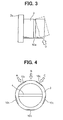
- FIG. 3 is a view for explaining a removing operation of a core from the throttle body;
- FIG. 4 is a view showing of notches, according to a modification of the first embodiment; and
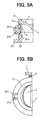
- FIG. 5A is a partial cross-sectional view of a throttle body according to a second embodiment of the present invention, and FIG. 5B is a top view showing the throttle body of FIG. 5A.
-
- As shown in FIGS. 1 and 2, a
throttle body 1 includes abody member 3, athrottle shaft 4, athrottle valve 5 and aninsert core 6. Thebody member 3 has a substantial cylindrical-shape and defines anair intake passage 2 therein. Thebody member 3 is made of thermoplastic engineering plastic such as PBT (poly butylene terephthalate) resin and PPS (polyphenylene sulfide) resin. Theinsert core 6 is integrally provided within thebody member 3 by insert-molding and defines theair intake passage 2. Theinsert core 6 is made of a material different from the resin of thebody member 3, for example, iron and aluminum alloy. Thethrottle shaft 4 is rotatably provided in thebody member 3 in the proximity of theinsert core 6. Thethrottle valve 5 is attached to thethrottle shaft 4 so as to open/close theair intake passage 2. - The
throttle shaft 4 is supported at bearing portions provided on theinsert core 6 through bearing bushes (not shown). Both side ends of thethrottle shaft 4 penetrate through the cylindrical wall of thebody member 3. Anacceleration lever 7 is provided at one of side ends of thethrottle shaft 4. An acceleration wire (not shown) interlocked to an acceleration pedal (not shown) is wound around theacceleration lever 7. A return spring 8 is interposed between theacceleration lever 7 and thebody member 3 to bias theacceleration lever 7 in a direction to fully close thethrottle valve 5. - The
body member 3 has fourflanges 3a to mount thethrottle body 1 onto the engine. For example, the fourflanges 3a are positioned substantially at four corners in a rectangular shape. Similar to theinsert core 6,collars 9 are integrally provided within theflanges 3a by insert-molding. Thecollars 9 are made of a material, such as iron, different from the resin. - As shown in FIGS. 1 and 2,
notches resinous body member 3. Thenotch 10a is entirely circumferentially or partially formed on the outer cylindrical wall of thebody member 3 in an identical circumferential direction of thebody member 3, in the proximity of a position where theinsert core 6 is casted. Thenotches 10b are formed on the outer walls of theflanges 3a in which thecollars 9 are casted, in the axial direction of thecollars 9. - According to this structure, when bending force larger than a predetermined force is applied to the
throttle body 1 while thethrottle body 1 is dismantled (disassembled) after it is used, thebody member 3 is split at thenotch 10a. Therefore, theinsert core 6 is readily removed from thebody member 3. Further, when external force larger than a predetermined force is applied to thenotches 10b, theflanges 3a are readily split at thenotches 10b. Therefore, it is easy to remove thecollars 9 made of the different material from theresinous body member 3. - The
notch 10a is formed on the outer cylindrical wall of thebody member 3 at a position corresponding to a substantially middle of theinsert core 6 in the axial direction of thebody member 3. Therefore, when thethrottle body 1 is split at thenotch 10a while thethrottle body 1 is dismantled after it is used, at least half of theinsert core 6 is exposed from the splitresinous body member 3. Accordingly, theinsert core 6 is readily clamped (grasped) at the exposed portion, and can be readily removed from the resin parts. - A cross section of the
notch 10a is a V-shaped groove. As shown in FIG. 3, when external force larger than the predetermined force is applied to an end of thethrottle body 1, for example, as indicated by an arrow D, while thethrottle body 1 is dismantled, stresses by the external force are concentrated to the bottom of the V-shaped groove. Therefore, thethrottle body 1 is readily split at thenotch 10a. More particularly, when thethrottle body 1 is dismantled, thethrottle body 1 is clamped at one side, for example, at theflanges 3a. Then, the external force is applied to the other side as indicated by the arrow D. Thus, thebody member 3 is split at thenotch 10a and separated as shown in a broken line in FIG. 3. - As shown in FIG. 4,
notches 10c can be provided in place of thenotch 10a. Thenotches 10c are discontinuously and separately formed in an identical circumferential direction of thecylindrical body member 3. Preferably, an odd number of thenotches 10c is arranged at equal intervals. In FIG. 4, fivenotches 10c are provided, for example. Thenotches 10c are not arranged symmetrically with respect to the axis of thethrottle body 1. Therefore, in a case that bending force is applied to thethrottle body 1 against the axial direction while thethrottle body 1 is used, the force is substantially equally affected thereto irrespective of positional difference in the identical peripheral direction. That is, thethrottle body 1 has a substantially equal bending resistance against any bending forces applied in arrow A, B or C direction in FIG. 4. Therefore, thethrottle body 1 suitably maintains its strength while it is used. - Next, a second embodiment of the present invention is described with reference to FIGS. 5A and 5B. In the second embodiment, the
body member 3 of thethrottle body 1 includes anupper body 31 and alower body 32. Both of theupper body 31 and thelower body 32 are made of resin, and fitted to each other with a hook. As shown in FIG. 5A, theupper body 31 forms arecess 31a on the inner peripheral wall thereof for receiving theinsert core 6. Also, an insertion hook 31b having resiliency is provided in theupper body 31 to be fitted to thelower body 32. Thelower body 32 forms a recess 32a on the inner peripheral wall thereof for receiving theinsert core 6. Also, thelower body 32 provides ahook receiving portion 32b for receiving the insertion hook 31b and aflange 32c through which thethrottle body 1 is mounted on the engine. - During an assembly of the
throttle body 1, theinsert core 6 is fitted in therecesses 31a and 32a so as to be held between theupper body 31 and thelower body 32. Further, the insertion hook 31b of theupper body 31 is inserted into thehook receiving portion 32b of thelower body 32 so that theupper body 31 and thelower body 32 are fitted with the hook 31b while holding theinsert core 6 therebetween. That is, both of theupper body 31 and thelower body 32 are connected by a snap-fitted connection. In this way, thethrottle body 1 is readily assembled. On the other hand, during the disassembly of thethrottle body 1, both of thebodies insert core 6 are readily separated from each other by unhooking the hook 31b from thehook receiving portion 32b without using a specific tool. - In the above assembly of the
throttle body 1, each of theupper body 31, thelower body 32 and theinsert core 6 is described as an individual component. However, theinsert core 6 may be integrated beforehand with one of theupper body 31 and thelower body 32 by insert molding. Further, therecesses 31a and 32a may be provided one of the first and thesecond bodies - In the
throttle body 1 according to the present invention, after it is used, it is easy to disassemble thethrottle body 1 into the resinous body and the different material parts such as theinsert core 6 andcollars 9 without using the specific tool. Therefore, the above components, which are conventionally disposed or buried, are recyclable. - In the above embodiments, the present invention is exemplarily adopted to the throttle body. However, the present invention may be used to any insert-molded member in which a resinous body and a part made of a different material are integrally molded. In this case, a notch is entirely circumferentially or partially provided on the outer wall of the insert-molded member in the proximity of a position where the different material part is molded, similar to the case of the
throttle body 1. Thus, during disassembly (dismantling), when the external force larger than the predetermined force is applied to one end of the insert-molded member, the insert-molded member is readily split at the notch. As a result, the different material parts are readily removed from the resinous body, thereby making recycling easy. - The present invention should not be limited to the disclosed embodiments, but may be implemented in other ways without departing from the spirit of the invention.
- In a throttle body (1), a cylindrical body member (3) is made of resin, and a core (6) is made of a material different from the body member (3) and insert molded in the body member (3). A notch (10a, 10c) is provided on an outer surface of the body in a peripheral direction, in a proximity of the core (6). The body member (3) is readily split at the notch (10a, 10c) when external force is applied to the body member (3) during a dismantling. Therefore, the core (6) is readily removed from the body member (3). Alternatively, the body member (3) can be constructed of a first body (31) having a hook (31b) and a second body (32) having a hook-receiving portion (32b). Both the first and second bodies (31, 32) are connected to each other through the hook (31b) and the hook-receiving portion (32b), and the core (6) is held between both the first and second bodies (31, 32). Thus, the core (6) is readily removed from the bodies (31, 32) by unhooking the hook (31b).
Claims (20)
- A throttle body (1) for an engine comprising:wherein the body member (3) has a notch (10a, 10c) which is notched on an outer surface of the body member (3) at least at a part in a circumferential direction of the body member (3) in a proximity of a position where the core (6) is inserted.a body member (3) made of resin and having a substantially cylindrical-shape for defining an air intake passage (2) therein; anda core (6) made of a material different from that of the body member (3), and insert-molded within the body member (3) while the body member (3) is resin-molded,
- The throttle body (1) according to claim 1, wherein the notch (10a) is continuously provided in the body member (3) in an identical circumferential direction.
- The throttle body (1) according to claim 1 or 2, wherein the notch (10a) is entirely circumferentially provided in the body member (3) in an identical circumferential direction.
- The throttle body (1) according to claim 1, wherein the notch (10c) includes a plurality of notch portions discontinuously provided in the body member (3) in an identical circumferential direction.
- The throttle body (1) according to claim 1 or 4, wherein the notch (10c) has an odd number of notch portions and the notch portions are separately arranged in the body member (3) at substantially equal intervals in an identical circumferential direction.
- The throttle body (1) according to any one of claims 1 to 5, wherein the notch (10a, 10c) is arranged on the outer surface of the body member (3) at a part corresponding to a substantially middle of the core (6) in an axial direction of the body member (3).
- The throttle body (1) according to any one of claims 1 to 6, further comprising:wherein the flange (3a) has a notch (10b) that is notched on an outer surface of the flange (3a) in a proximity of the collar (9); anda flange (3a) integrally provided with the body member (3), the body member (3) being mounted on the engine through the flange (3a); anda collar (9) made of a material different from that of the flange (3a) and insert-molded in the flange (3a) while the flange (3a) is resin-molded,
wherein the notch (10b) is provided in the flange (3a) in an axial direction of the body member (3). - The throttle body (1) according to any one of claims 1 to 7,
wherein the notch (10a, 10b, 10c) has a substantially V-shape in cross-section. - The throttle body (1) according to any one of claims 1 to 8, further comprising:a throttle shaft (4) rotatably provided in the body member (3) at a position corresponding to the core (6) in an axial direction of the body member (3);a throttle valve (5) provided on the throttle shaft (4) to open and close the air intake passage (2).
- A throttle body (1) for an engine comprising:a first body member (31) that is a substantial cylindrical-shape for defining an air intake passage (2) therein, made of resin, and having a hook (31b);a second body member (32) that is a substantial cylindrical-shape for defining the air intake passage (2) therein, made of resin, and having a hook-receiving portion (32b) engaged with the hook (31b); anda core (6) made of a material different from the resin of the first and the second body members(31, 32), provided in a proximity of a connecting portion between the first and the second body members (31, 32), the core (6) being disposed in the first and the second body members (31, 32) to define the air intake passage (2).
- The throttle body (1) according to claim 10,
wherein at least one of the first and the second body members (31, 32) has a recess (31a, 32a) on an inner surface thereof for receiving the core (6), and the core (6) is held by the first and the second body members (31, 32) in the recess (31a, 32a). - The throttle body (1) according to claim 10 or 11, further comprising:a throttle shaft (4) rotatably provided in at least one of the first and the second body members (31,32) at a position corresponding to the core (6) in an axial direction of the first and the second body members(31, 32); anda throttle valve (5) provided on the throttle shaft (4) to open and close the air intake passage (2).
- The throttle body (1) according to any one of claims 10 to 12,
wherein the core (6) is integrated with one of the first and the second body members (31, 32) by an insert-molding. - A molded unit (1) comprising:wherein the body (3) has a notch (10a, 10b, 10c) which is notched on an outer surface of the body (3) at a position proximate to the insert member (6, 9).a body (3) made of resin; andan insert member (6, 9) made of a material different from that of the body, and insert-molded in the body (3),
- The molded unit (1) according to claim 14, wherein the body (3) provides a flange (3a) for fixing the body (3), and the insert member (9) is insert-molded in the flange (3a).
- The molded unit (1) according to claim 15, wherein the insert member is a collar (9), and the notch (10b) is formed on outer surface of the flange (3a) in an axial direction of the collar (9).
- The molded unit (1) according to claim 14, wherein the body (3) is a substantial cylindrical-shape, and the notch (10a) is continuously formed on an outer surface of the body (3) in an identical circumferential direction.
- The molded unit (1) according to claim 14, wherein the body (3) is a substantial cylindrical-shape, and the notch (10c) is partially formed on an outer surface of the body (3) in an identical circumferential direction.
- The molded unit (1) according to claim 14 or 18, wherein the notch (10c) has an odd number of notch portions on an outer side surface of the body (3), and the odd number of notch portions is discontinuously arranged in the body (3) at substantially equal intervals in an identical peripheral direction.
- The molded unit (1) according to any one of claims 14 to 19, wherein the body (3) is split at the notch (10a, 10b, 10c) and the insert member (6, 9) is exposed from the body (3), when an external force larger than a predetermined force is applied to the body (3) against an axial direction of the body (3).
Applications Claiming Priority (4)
| Application Number | Priority Date | Filing Date | Title |
|---|---|---|---|
| JP2001020429 | 2001-01-29 | ||
| JP2001020429 | 2001-01-29 | ||
| JP2001358116 | 2001-11-22 | ||
| JP2001358116A JP2002295273A (en) | 2001-01-29 | 2001-11-22 | Insert molding and throttle body formed therefrom |
Publications (2)
| Publication Number | Publication Date |
|---|---|
| EP1227228A2 true EP1227228A2 (en) | 2002-07-31 |
| EP1227228A3 EP1227228A3 (en) | 2004-01-14 |
Family
ID=26608456
Family Applications (1)
| Application Number | Title | Priority Date | Filing Date |
|---|---|---|---|
| EP20020001428 Withdrawn EP1227228A3 (en) | 2001-01-29 | 2002-01-21 | Throttle body with insert-molded member |
Country Status (3)
| Country | Link |
|---|---|
| US (1) | US6722633B2 (en) |
| EP (1) | EP1227228A3 (en) |
| JP (1) | JP2002295273A (en) |
Cited By (3)
| Publication number | Priority date | Publication date | Assignee | Title |
|---|---|---|---|---|
| EP1498596A3 (en) * | 2003-07-17 | 2005-06-08 | Arno Hofmann | Throttle slit seal for valves |
| ITBO20120312A1 (en) * | 2012-06-06 | 2013-12-07 | Magneti Marelli Spa | BUTTERFLY VALVE FOR AN INTERNAL COMBUSTION ENGINE PROVIDED WITH A METALLIC VALVE SEAT MOLDED INSIDE A BODY VALVE IN PLASTIC MATERIAL |
| EP3480444A1 (en) * | 2015-11-19 | 2019-05-08 | Continental Automotive GmbH | Electronic throttle |
Families Citing this family (5)
| Publication number | Priority date | Publication date | Assignee | Title |
|---|---|---|---|---|
| DE10147333A1 (en) * | 2001-09-26 | 2003-04-24 | Bosch Gmbh Robert | Reduced throttle device with interchangeable housing parts |
| DE10156213A1 (en) * | 2001-11-15 | 2003-06-05 | Siemens Ag | throttle body |
| US8997782B2 (en) * | 2010-09-24 | 2015-04-07 | Brunswick Corporation | Inlet control valves for use with fuel delivery systems |
| USD828399S1 (en) * | 2017-02-27 | 2018-09-11 | Chandler Fitzgerald | Throttle body coupler |
| JP2024082629A (en) * | 2022-12-08 | 2024-06-20 | トヨタ自動車株式会社 | Intake manifold |
Citations (2)
| Publication number | Priority date | Publication date | Assignee | Title |
|---|---|---|---|---|
| JPH10306736A (en) | 1997-05-08 | 1998-11-17 | Aisan Ind Co Ltd | Throttle body |
| JP2000313309A (en) * | 1999-04-28 | 2000-11-14 | Tokai Rika Co Ltd | Through anchor |
Family Cites Families (11)
| Publication number | Priority date | Publication date | Assignee | Title |
|---|---|---|---|---|
| US4753458A (en) * | 1986-08-28 | 1988-06-28 | Harvard Industries, Inc. | Quick connector assembly |
| DE4024042C1 (en) | 1990-07-28 | 1991-10-10 | Schneider Fassadenplanung Gmbh, 8882 Lauingen, De | Anchor nut for riveting welding etc. - is weldable, threaded sleeve, with separable protection head at end away from welding collar |
| DE4029002A1 (en) | 1990-09-13 | 1992-03-19 | Vdo Schindling | ADJUSTMENT ELEMENT AND THROTTLE VALVE CONNECTOR WITH SUCH A |
| JP2612099B2 (en) | 1991-01-29 | 1997-05-21 | 株式会社日立製作所 | Throttle valve assembly |
| DE19531365C2 (en) | 1995-08-25 | 1998-11-05 | Knorr Bremse Systeme | Method of manufacturing a connecting rod, especially for compressors |
| US5794591A (en) | 1997-03-17 | 1998-08-18 | Ford Motor Company | Throttle valve for an internal combustion engine |
| US5988131A (en) | 1997-12-23 | 1999-11-23 | Ford Global Technologies, Inc. | Air intake system with composite throttle body |
| JPH11310025A (en) | 1998-04-27 | 1999-11-09 | Denso Corp | Vehicle air conditioner |
| JP2000127744A (en) | 1998-10-23 | 2000-05-09 | Denso Corp | Air conditioner |
| EP1083317A3 (en) * | 1999-09-08 | 2001-09-05 | Siemens Canada limited | Throttle body insert for intake manifold |
| IT246930Y1 (en) * | 1999-12-09 | 2002-04-10 | Bonomi Bresciane Rubinetterie | INTERCEPTION VALVE FOR FLUIDS WITH BUTTERFLY SHUTTER ORDER WITH HIGH RELIABILITY OF OPERATION |
-
2001
- 2001-11-22 JP JP2001358116A patent/JP2002295273A/en active Pending
-
2002
- 2002-01-16 US US10/046,305 patent/US6722633B2/en not_active Expired - Fee Related
- 2002-01-21 EP EP20020001428 patent/EP1227228A3/en not_active Withdrawn
Patent Citations (2)
| Publication number | Priority date | Publication date | Assignee | Title |
|---|---|---|---|---|
| JPH10306736A (en) | 1997-05-08 | 1998-11-17 | Aisan Ind Co Ltd | Throttle body |
| JP2000313309A (en) * | 1999-04-28 | 2000-11-14 | Tokai Rika Co Ltd | Through anchor |
Cited By (3)
| Publication number | Priority date | Publication date | Assignee | Title |
|---|---|---|---|---|
| EP1498596A3 (en) * | 2003-07-17 | 2005-06-08 | Arno Hofmann | Throttle slit seal for valves |
| ITBO20120312A1 (en) * | 2012-06-06 | 2013-12-07 | Magneti Marelli Spa | BUTTERFLY VALVE FOR AN INTERNAL COMBUSTION ENGINE PROVIDED WITH A METALLIC VALVE SEAT MOLDED INSIDE A BODY VALVE IN PLASTIC MATERIAL |
| EP3480444A1 (en) * | 2015-11-19 | 2019-05-08 | Continental Automotive GmbH | Electronic throttle |
Also Published As
| Publication number | Publication date |
|---|---|
| JP2002295273A (en) | 2002-10-09 |
| US6722633B2 (en) | 2004-04-20 |
| US20020100892A1 (en) | 2002-08-01 |
| EP1227228A3 (en) | 2004-01-14 |
Similar Documents
| Publication | Publication Date | Title |
|---|---|---|
| CA1232748A (en) | Method of manufacturing motor | |
| US8142073B2 (en) | Snap-fit sensor assembly | |
| US6722633B2 (en) | Throttle body with insert-molded member | |
| US9371840B2 (en) | Centrifugal blowing fan | |
| US20080197737A1 (en) | Permanent magnet rotor assembly | |
| EP0547767B1 (en) | A rotor for rotary electrical machinery | |
| US20130243358A1 (en) | Split bearing cage | |
| US8339011B2 (en) | Rotor assembly wire support | |
| KR20190005977A (en) | Method for manufacturing rotors and rotors | |
| EP3842734B1 (en) | Electronically controlled throttle device for engine | |
| JPH06153427A (en) | Rotor fitted with permanent magnet | |
| US7458557B2 (en) | Electromagnetic valve | |
| US5756890A (en) | Snap mount throttle position sensor | |
| JP5298402B2 (en) | Motor end plate structure | |
| JP2000188838A (en) | Motor rotor and method of manufacturing the same | |
| US5058821A (en) | Coil bobbin | |
| US6692675B2 (en) | Method of producing a control valve assembly | |
| JP4531463B2 (en) | Electromagnetic actuator | |
| CN100503293C (en) | Operating lever system | |
| JPH062952U (en) | Resin mold motor | |
| JP2006177460A (en) | Packing manufacturing method | |
| EP3242378B1 (en) | Rotor group for electromechanical components and method for manufacturing said rotor group | |
| JPH11215779A (en) | Motor rotor | |
| JP3839938B2 (en) | Slide bearing and sliding member | |
| JP7480613B2 (en) | Plastic moldings |
Legal Events
| Date | Code | Title | Description |
|---|---|---|---|
| PUAI | Public reference made under article 153(3) epc to a published international application that has entered the european phase |
Free format text: ORIGINAL CODE: 0009012 |
|
| AK | Designated contracting states |
Kind code of ref document: A2 Designated state(s): AT BE CH CY DE DK ES FI FR GB GR IE IT LI LU MC NL PT SE TR |
|
| AX | Request for extension of the european patent |
Free format text: AL;LT;LV;MK;RO;SI |
|
| PUAL | Search report despatched |
Free format text: ORIGINAL CODE: 0009013 |
|
| AK | Designated contracting states |
Kind code of ref document: A3 Designated state(s): AT BE CH CY DE DK ES FI FR GB GR IE IT LI LU MC NL PT SE TR |
|
| AX | Request for extension of the european patent |
Extension state: AL LT LV MK RO SI |
|
| 17P | Request for examination filed |
Effective date: 20040311 |
|
| AKX | Designation fees paid |
Designated state(s): DE FR GB |
|
| GRAP | Despatch of communication of intention to grant a patent |
Free format text: ORIGINAL CODE: EPIDOSNIGR1 |
|
| STAA | Information on the status of an ep patent application or granted ep patent |
Free format text: STATUS: THE APPLICATION IS DEEMED TO BE WITHDRAWN |
|
| 18D | Application deemed to be withdrawn |
Effective date: 20070807 |