EP1227186A1 - Line switch part snow melting device - Google Patents
Line switch part snow melting device Download PDFInfo
- Publication number
- EP1227186A1 EP1227186A1 EP00969923A EP00969923A EP1227186A1 EP 1227186 A1 EP1227186 A1 EP 1227186A1 EP 00969923 A EP00969923 A EP 00969923A EP 00969923 A EP00969923 A EP 00969923A EP 1227186 A1 EP1227186 A1 EP 1227186A1
- Authority
- EP
- European Patent Office
- Prior art keywords
- heating
- railway track
- heating coil
- train
- track points
- Prior art date
- Legal status (The legal status is an assumption and is not a legal conclusion. Google has not performed a legal analysis and makes no representation as to the accuracy of the status listed.)
- Withdrawn
Links
Images






Classifications
-
- E—FIXED CONSTRUCTIONS
- E01—CONSTRUCTION OF ROADS, RAILWAYS, OR BRIDGES
- E01B—PERMANENT WAY; PERMANENT-WAY TOOLS; MACHINES FOR MAKING RAILWAYS OF ALL KINDS
- E01B7/00—Switches; Crossings
- E01B7/24—Heating of switches
Definitions
- the present invention relates to a thawing device for railway track points for preventing failures in points changing due to snow or icing at the points sections of railway tracks.
- thawing device for railway track points include, as a device for use in regions having large amounts of snow, a hot air blower type of thawing device, wherein kerosene or the like is burnt and hot air generated thereby is blown via a duct onto the points sections. Furthermore, as a device for use in regions having small amounts of snow, there is an electric heater type thawing device, wherein electric heaters are placed on the main rails and the side regions of floor plates, thereby heating the points sections.
- these conventional thawing devices have following problems: in the case of the hot air blower type of thawing device, although the thawing capacity is excellent, there have been problems in that the heating efficiency is poor and hence fuel expenses are high, there is a risk of accidental fire, and disassembly and maintenance must be carried out in the season when the device is out of use. In the case of the electric heater type thawing device, there have been problems in that the thawing capacity is low, the rate of temperature increase is slow, and ease of installation is poor, given that a special floor plate is used, and the like.
- an object of the present invention is to provide a thawing device for railway track points sections which solves the above-mentioned problems by lowering running costs by means of highly efficient heating, and which secures safety by reducing the effects on other devices of the magnetic flux caused by the high-frequency current.
- a thawing device for railway track points is characterized by including: a heating coil wound around a floor plate for heating the floor plate by induction; and an inverter device for supplying high-frequency current to the heating coil.
- the heating coil is wound around the floor plate and the heating surface area is increased, and hence the floor plate is heated at high-power with a high-frequency current, and a good effect in preventing ice formation on the floor plate and/or rails is obtained by thermal conduction from the floor plate to a main rail and tongue rails.
- the heating coil does not project significantly beyond a sleeper, it does not obstruct track maintenance work, and does not require detachment outside of the snow season.
- the heating coil is wound through one or more turns in contact with the side face or the lower face of the floor plate.
- the heating surface area is increased further, floor plate induction heating is performed at high-power, and a highly effective thawing capacity is achieved.
- the heating coil is wound in contact with the upper face of the floor plate.
- the heating coil can be wound around the floor plate even in cases where the floor plates of the left and right-hand rails are connected, for example, at the front end portion of a railway points, or in cases where the floor plate is long.
- a thawing device for railway track points is characterized by including: a heating coil wound around a floor plate for heating the floor plate by induction; an inverter device for supplying high-frequency current to the heating coil; and a protection against coil magnetism for preventing magnetic flux of the heating coil from leaking.
- the protection against coil magnetism is constituted by a cover made of a material having high resistivity and high magnetic permeability, which covers the periphery of the heating coil wound around the floor plate.
- the protection against coil magnetism may be constituted by first closed loop conductors disposed about the outer circumference of a single heating coil or a plurality of heating coils wound around the floor plates, and second closed loop conductors disposed around the periphery of the first closed loop conductors.
- first closed loop conductors disposed about the outer circumference of a single heating coil or a plurality of heating coils wound around the floor plates
- second closed loop conductors disposed around the periphery of the first closed loop conductors.
- a thawing device for railway track points is characterized in that a plurality of heating coils wound around floor plates for heating the floor plates by induction are connected in series by means of a feeder cable, these heating coils are connected by means of connection cables with a single inverter device for supplying high-frequency current to the beating coils, and a protection against cable magnetism is provided for preventing magnetic flux of the cables from leaking.
- the protection against cable magnetism is constituted by twisting the supply or return connection cables from the inverter device to the heating coils, and the feeder cable.
- the protection against cable magnetism may be constituted by covers which cover the periphery of the supply and return connection cables from the inverter device to the heating coils, and the feeder cable, and which are connected in a closed loop in the vicinity of the heating coils and the inverter device.
- the protection against cable magnetism may be constituted by superposing coils wherein portions of the supply and return connection cables are wound respectively in the same direction, to the same diameter, and through the same number of turns.
- the magnetic fluxes induced by the high-frequency current in the supply and return connection cables cancel out mutually, and the area peripheral to the cables is protected against magnetism and the effects of high-frequency noise on other devices are reduced.
- a thawing device for railway track points is characterized by including: a heating coil for heating a floor plate by induction; an inverter device for supplying high-frequency current to the heating coil; a train detecting device for detecting the approach of a train to a points section; and an inverter controller for outputting a signal to the inverter device, the signal for either reducing or interrupting the supply of high-frequency current to the heating coil for a prescribed period of time after the approach of a train has been detected by the train detecting device.
- the supply of high-frequency current from the inverter device to the heating coil is either reduced or interrupted for a prescribed period of time after the approach of a train is detected. Thereby, the effects of the high-frequency noise on the high-precision equipment of the train are reduced, when the train is passing over the points section.
- the train detecting device includes a magnetic field detector for converting an electrical signal into a magnetic flux and detecting changes in magnetic field caused by the approach of a train.
- the magnetic flux generated by the coil or the like of the magnetic field detector the magnetic resistance will change if a portion of a train, namely, a train wheel, is present.
- the approach of a train is detected, whereupon, for a prescribed period of time, the supply of high-frequency current to the heating coil is reduced or interrupted, thereby reducing the effects of high-frequency noise on the high-precision equipment of a train when the train is passing over a points section.
- the train detecting device may be constituted by a signal transmitter for inputting a track path signal indicating whether a short circuit is caused between the left and right-hand rails by an axle of a train within a prescribed section, and transmitting a train present/absent signal; and a signal receiver for receiving the transmitted train present/absent signal.
- a train present signal is output from the signal transmitter to the signal receiver, whereby the train detecting device detects that a train is passing through, or is halted in, the points section.
- the supply of high-frequency current to the heating coil is reduced or interrupted for a prescribed period of time, and hence the effects of high-frequency noise on the high-precision equipment of a train is reduced when the train is passing through a points section.
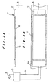
- FIG. 1a denotes a heating coil which is wound along the side face of a floor plate 2 and accommodated inside a heating coil case 1c.
- the heating coil 1a is connected by a connection cable 4 to an inverter device 5 which supplies high-frequency current from a commercial power source 3.
- a high-frequency current is supplied to the heating coil 1a, a high-frequency magnetic field is generated therein, and the floor plate 2 is induction heated by this high-frequency magnetic field. Heat generated in the floor plate 2 is transferred to a main rail 6 and a tongue rail 7, thereby raising the temperature of these rails 6 and 7.
- any snow or ice present on the floor plate 2 or rails 6 and 7 is caused to melt, and hence points changing failures are prevented.
- the heating coil 1a is wound once or more times around the side face of the floor plate 2, induction heating is performed at high-power, and a good effect in preventing ice formation is achieved by thermal conduction to the rails 6 and 7. Additionally, since the heating coil 1a does not project significantly beyond a railway sleeper 8, it does not interfere with track maintenance tasks such as ballast packing or the like, and does not need to be removed outside of the snow season.
- the thawing device for railway track points is constituted by winding the heating coil 1a accommodated in the heating coil casing 1c, one or more times in contact with the lower face of the floor plate 2.
- the construction is the same as that in the first embodiment, and high-frequency current is supplied to the heating coil 1a from the commercial power source 3, via the inverter device 5.
- the heating coil 1a generates a high-frequency magnetic field due to the high-frequency current supplied thereto, and the floor plate 2 is induction heated by the magnetic field. Heat generated in the floor plate 2 is transferred to the main rail 6 and tongue rail 7, thereby raising the temperature of these rails 6 and 7.
- any snow or ice present on the floor plate 2 or the rails 6 and 7 is caused to melt, thereby preventing points changing failures.
- the heating coil 1a is wound one or more times in contact with the lower face of the floor plate 2, induction heating is performed at high-power, and a good effect in preventing ice formation is achieved by thermal conduction to the rails 6 and 7. Additionally, since the heating coil 1a does not project significantly beyond the railway sleeper 8, it does not interfere with track maintenance tasks such as ballast packing or the like, and does not need to be removed outside of the snow season.
- the thawing device for railway track points is constituted such that the heating coil 1a is wound along the side face of the floor plate 2, but at a position which does not interfere with the opening and closing operation of the tongue rail 7, a portion P of the heating coil 1a is wound in contact with the upper surface of the floor plate 2.
- a fourth embodiment of the present invention is described with reference to Figs. 4A to 4C.
- the periphery of the heating coil 1a wound along the side face of the floor plate.2 is covered by a protection against coil magnetism 9, which prevents the magnetic flux of the heating coil 1a from leaking.
- the protection against coil magnetism 9 is made from a material having high resistivity and high magnetic permeability, such as ferrite, and forms a closed magnetic circuit with the side face of the floor plate 2, whereby leakage of magnetic flux from the high-frequency magnetic field generated in the heating coil 1a is reduced, and induction heating of the protection against coil magnetism 9 itself is suppressed.
- the basic construction is similar to that of the various embodiments described above, heat generated in the floor plate 2 being transferred to the main rail 6 and tongue rail 7, thereby causing snow or ice present on the floor plate 2 or rails 6 and 7 to melt and hence preventing failures in points changing.
- a fifth embodiment of the invention is described with reference to Fig. 5.
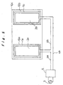
- a first closed loop conductor 10a is disposed about the outer circumference of a first heating coil 1a positioned about the periphery of a first floor plate 2a
- a second closed loop conductor 10b is disposed about the outer circumference of a second heating coil 1b positioned about the periphery of a second floor plate 2b
- a third closed loop conductor 10c is disposed about the outer circumferences of these two closed loop conductors 10a and 10b, a protection against coil magnetism being constituted by these conductors 10a, 10b, and 10c.
- numeral 4a in Fig. 5 denotes a connection cable which connects the heating coils 1a and 1b to the inverter device 5
- numeral 4b is a feeder cable.
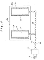
- a protection against coil magnetism is constituted by respectively disposing conductors 10a to 10c about the circumferences of the heating coils 1a and 1b wound respectively around the floor plates 2a and 2b, in addition to which a protection against magnetism is also provided for the cables. More specifically, the heating coils 1a and 1b are connected in series by means of the feeder cable 4b, and furthermore, a protection against cable magnetism is constituted by twisting the supply connection cable and the return connection cable 4a and 4a, and also the feeder cable 4b, along which the high-frequency current passes.
- the high-frequency current flows in opposite directions in the supply and return cables, and the high-frequency magnetic fields generated in the twisted connection cables 4a and 4a also act in opposite directions, thereby cancelling each other out, and hence preventing leakage of magnetic flux of the cables.
- a seventh embodiment of the invention is described with reference to Fig. 7.
- the heating coils 1a and 1b wound respectively along the floor plates 2a and 2b are connected in series via the feeder cable 4b and two connection cables 4a and 4c, to the single inverter device 5.
- a protection against cable magnetism is constituted by covering these three cables 4a, 4b, and 4c by means of shields (cable magnetism-proof covers) 11a, 11b, and 11c.
- the shields 11a, 11b, and 11c are connected at three locations in the vicinity of the heating coils 1a and 1b and in the vicinity of the inverter device 5, in such a manner that they form a closed loop.
- FIG. 8 An eighth embodiment of the invention is described with reference to Fig. 8.
- the heating coils 1a and 1b wound respectively along the floor plates 2a and 2b are connected in series by means of the feeder cable 4b and two connection cables 4a and 4c, to the single inverter device 5.
- a protection against cable magnetism is constituted by superposing two coils 12a and 12b which are formed by winding respective portions of the two connection cables 4a and 4c in the same direction, to the same diameter, and by the same number of turns.
- a ninth embodiment of the invention is described with reference to Figs. 9A to 9C.
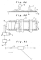
- a high-frequency current is supplied by the inverter device 5 to the heating coil 1a (numeral 1c indicates the casing inside which the coil is accommodated) wound around the side face of the floor plate 2, and the floor plate 2 is induction heated by means of the high-frequency magnetic field generated by the high-frequency current.
- a train detecting device 14 is disposed in front of a points section 13 in the direction of travel of the trains, as indicated by the arrow in Fig. 9C, and is connected via an inverter controller 15 to the inverter device 5.
- the inverter controller 15 inputs an approach signal when a train has approached the points section 13, and after detecting this as an approach signal, for a prescribed period of time, it outputs a signal to the inverter device 5 whereby the supply of high-frequency current to the heating coil 1a is reduced or halted.
- the train detecting device 14 as described in the ninth embodiment is disposed on the central portion of the main rail 6.
- the train detecting device 14 is constituted by a signal generator 18 for generating a signal from the commercial power source 3, a magnetic field detector 19 for converting an electrical signal to a magnetic flux, and an amplifier 20 for amplifying the signal.
- a coil 19a generating a magnetic field is used.
- the train detecting device 14 detects the approach of a train due to a change in impedance, then the signal generator 18 generates a signal and said signal is transmitted to the inverter controller 15 via the amplifier 20.
- the train detecting device 14 of the present embodiment the presence or absence of a train is detected by means of a change in the impedance of the coil 19a and a change in the signal current, due to change in the magnetic field according to whether or not a train is present.
- the effect of the high-frequency noise generated at the points section on the high-precision equipment of the train is reduced, by either reducing or interrupting the supply of high-frequency current to the heating coil 1a.
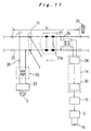
- the thawing device for railway track points has the same basic construction as that in the first to eighth embodiments, and further includes the train detecting device 14 provided in front of the points section 13 in the direction of travel of the trains, as indicated by the arrow in the Figure. More specifically, in a specific section N comprising a prescribed distance of the railway track, a transit path circuit is formed by the right and left rails 21 and 22, and a signal generator 23 supplies an excitation signal from the commercial power source 3 to a transit path relay 24, by means of a transit path transformer 25 and a resistor 26.
- the excitation signal supplied to the transit path relay 24 is reduced.
- a signal transmitter 28 is connected to the transit path relay 24, a signal device 29 and a signal receiver 30, and if it is judged from a change in the excitation signal supplied to the transit path relay 24 that the train 27 is present inside the specific section N, then the signal device 29 automatically operates and outputs a train present signal to the signal receiver 30.
- the train detecting device 14 is constituted by the signal receiver 30 and the signal transmitter 28.
- the inverter controller 15 is connected to the train detecting device 14 and if it is judged that the train 27 is passing through, or has halted in the points section 13 within the specified section N, then the controller outputs a signal to the inverter device 5 whereby the supply of high-frequency current to the heating coil 1a is either reduced or interrupted.
- a thawing device for railway track points which has a good effect in preventing ice formation on floor plates, main rails and tongue rails, by high-power induction heating using high-frequency electric current, and which, furthermore, does not require removal outside of the snow season.
- the thawing device for railway track points according to the present invention is beneficial in that it achieves heating of high efficiency by using high-frequency current, whilst also securing safety by suppressing the effects of the magnetic flux caused by the high-frequency current on other devices and on the high-precision equipment of the trains.
Landscapes
- Engineering & Computer Science (AREA)
- Mechanical Engineering (AREA)
- Architecture (AREA)
- Civil Engineering (AREA)
- Structural Engineering (AREA)
- Train Traffic Observation, Control, And Security (AREA)
- General Induction Heating (AREA)
Abstract
A thawing device for railway track points is constituted
by connecting a heating coil (1a) wound around a floor plate
(2) for heating the floor plate (2) by induction to an
inverter device (5) for supplying high-frequency current to
the heating coil (1a), via a connection cable (4); and
providing a protection against magnetism (9, 10a-10c, 11a-11c,
12a, 12b) about the periphery of the heating coil (1a)
and the connection cable (4).
Description
The present invention relates to a thawing device for
railway track points for preventing failures in points
changing due to snow or icing at the points sections of
railway tracks.
Conventional types of thawing device for railway track
points include, as a device for use in regions having large
amounts of snow, a hot air blower type of thawing device,
wherein kerosene or the like is burnt and hot air generated
thereby is blown via a duct onto the points sections.
Furthermore, as a device for use in regions having small
amounts of snow, there is an electric heater type thawing
device, wherein electric heaters are placed on the main rails
and the side regions of floor plates, thereby heating the
points sections.
However, these conventional thawing devices have
following problems: in the case of the hot air blower type of
thawing device, although the thawing capacity is excellent,
there have been problems in that the heating efficiency is
poor and hence fuel expenses are high, there is a risk of
accidental fire, and disassembly and maintenance must be
carried out in the season when the device is out of use. In
the case of the electric heater type thawing device, there
have been problems in that the thawing capacity is low, the
rate of temperature increase is slow, and ease of
installation is poor, given that a special floor plate is
used, and the like.
In order to increase the heating efficiency, it may be
considered to use high-frequency current, but this brings a
risk that the magnetic flux created by the high-frequency
current may affect other devices.
Consequently, an object of the present invention is to
provide a thawing device for railway track points sections
which solves the above-mentioned problems by lowering running
costs by means of highly efficient heating, and which secures
safety by reducing the effects on other devices of the
magnetic flux caused by the high-frequency current.
A thawing device for railway track points according to a
first aspect of the present invention is characterized by
including: a heating coil wound around a floor plate for
heating the floor plate by induction; and an inverter device
for supplying high-frequency current to the heating coil. By
adopting this construction, the heating coil is wound around
the floor plate and the heating surface area is increased,
and hence the floor plate is heated at high-power with a
high-frequency current, and a good effect in preventing ice
formation on the floor plate and/or rails is obtained by
thermal conduction from the floor plate to a main rail and
tongue rails. Moreover, since the heating coil does not
project significantly beyond a sleeper, it does not obstruct
track maintenance work, and does not require detachment
outside of the snow season.
In the aforementioned construction, it is preferred that
the heating coil is wound through one or more turns in
contact with the side face or the lower face of the floor
plate. Thereby, the heating surface area is increased
further, floor plate induction heating is performed at high-power,
and a highly effective thawing capacity is achieved.
Further, it is preferred that a portion of the heating
coil is wound in contact with the upper face of the floor
plate. Thereby, the heating coil can be wound around the
floor plate even in cases where the floor plates of the left
and right-hand rails are connected, for example, at the front
end portion of a railway points, or in cases where the floor
plate is long.
A thawing device for railway track points according to a
second aspect of the invention is characterized by including:
a heating coil wound around a floor plate for heating the
floor plate by induction; an inverter device for supplying
high-frequency current to the heating coil; and a protection
against coil magnetism for preventing magnetic flux of the
heating coil from leaking. By adopting this construction,
leakage of magnetic flux from the high-frequency magnetic
field generated by the heating coil is reduced, thereby
reducing the effects of high-frequency noise on other
devices.
In the aforementioned construction, it is preferred that
the protection against coil magnetism is constituted by a
cover made of a material having high resistivity and high
magnetic permeability, which covers the periphery of the
heating coil wound around the floor plate. Thereby, leakage
of magnetic flux of the heating coil is prevented, and the
effects of high-frequency noise on other devices is reduced,
whilst at the same time suppressing any heating by induction
of the coil magnetism prevention means itself, due to the
magnetic flux.
Alternatively, the protection against coil magnetism may
be constituted by first closed loop conductors disposed about
the outer circumference of a single heating coil or a
plurality of heating coils wound around the floor plates, and
second closed loop conductors disposed around the periphery
of the first closed loop conductors. Thereby, an eddy current
which cancels out magnetic flux leaking from the first closed
loop is induced in the second closed loop conductors, and the
area peripheral to the heating coils is protected against
magnetism, and the effects of high-frequency noise on other
devices are reduced.
A thawing device for railway track points according to a
third aspect of the invention is characterized in that a
plurality of heating coils wound around floor plates for
heating the floor plates by induction are connected in series
by means of a feeder cable, these heating coils are connected
by means of connection cables with a single inverter device
for supplying high-frequency current to the beating coils,
and a protection against cable magnetism is provided for
preventing magnetic flux of the cables from leaking. By
adopting this construction, leakage of high-frequency
magnetic flux generated by the cables is reduced, thereby
reducing the effects of high-frequency noise on other
devices.
In the aforementioned construction, it is preferred that
the protection against cable magnetism is constituted by
twisting the supply or return connection cables from the
inverter device to the heating coils, and the feeder cable.
Thereby, the magnetic fluxes induced by the high-frequency
current in the supply and return cables cancel out mutually,
and the area peripheral to the cables is protected against
magnetism and the effects of high-frequency noise on other
devices are reduced.
Alternatively, the protection against cable magnetism
may be constituted by covers which cover the periphery of the
supply and return connection cables from the inverter device
to the heating coils, and the feeder cable, and which are
connected in a closed loop in the vicinity of the heating
coils and the inverter device. Thereby, an eddy current which
cancels out magnetic flux inside the closed loop having
leaked from the connection cables is induced in the covers of
the closed loop, and the area peripheral to the cables is
protected against magnetism and the effects of high-frequency
noise on other devices are reduced.
Alternatively, the protection against cable magnetism
may be constituted by superposing coils wherein portions of
the supply and return connection cables are wound
respectively in the same direction, to the same diameter, and
through the same number of turns. Thereby, the magnetic
fluxes induced by the high-frequency current in the supply
and return connection cables cancel out mutually, and the
area peripheral to the cables is protected against magnetism
and the effects of high-frequency noise on other devices are
reduced.
A thawing device for railway track points according to a
fourth aspect of the invention is characterized by including:
a heating coil for heating a floor plate by induction; an
inverter device for supplying high-frequency current to the
heating coil; a train detecting device for detecting the
approach of a train to a points section; and an inverter
controller for outputting a signal to the inverter device,
the signal for either reducing or interrupting the supply of
high-frequency current to the heating coil for a prescribed
period of time after the approach of a train has been
detected by the train detecting device. By adopting this
construction, the supply of high-frequency current from the
inverter device to the heating coil is either reduced or
interrupted for a prescribed period of time after the
approach of a train is detected. Thereby, the effects of the
high-frequency noise on the high-precision equipment of the
train are reduced, when the train is passing over the points
section.
In the aforementioned construction, it is preferred that
the train detecting device includes a magnetic field detector
for converting an electrical signal into a magnetic flux and
detecting changes in magnetic field caused by the approach of
a train. In the magnetic flux generated by the coil or the
like of the magnetic field detector, the magnetic resistance
will change if a portion of a train, namely, a train wheel,
is present. By detecting the changes in impedance and changes
in signal current corresponding to this change, the approach
of a train is detected, whereupon, for a prescribed period of
time, the supply of high-frequency current to the heating
coil is reduced or interrupted, thereby reducing the effects
of high-frequency noise on the high-precision equipment of a
train when the train is passing over a points section.
Alternatively, the train detecting device may be
constituted by a signal transmitter for inputting a track
path signal indicating whether a short circuit is caused
between the left and right-hand rails by an axle of a train
within a prescribed section, and transmitting a train
present/absent signal; and a signal receiver for receiving
the transmitted train present/absent signal. When a train
enters the prescribed section and the left and right-hand
rails are shorted by the train axle, a train present signal
is output from the signal transmitter to the signal receiver,
whereby the train detecting device detects that a train is
passing through, or is halted in, the points section.
Whereupon, the supply of high-frequency current to the
heating coil is reduced or interrupted for a prescribed
period of time, and hence the effects of high-frequency noise
on the high-precision equipment of a train is reduced when
the train is passing through a points section.
Preferred embodiments of the invention will be described
below with reference to Fig. 1A to Fig. 11.
A thawing device for railway track points according to a
first embodiment of the present invention is described with
reference to Figs. 1A and 1B. Numeral 1a denotes a heating
coil which is wound along the side face of a floor plate 2
and accommodated inside a heating coil case 1c. The heating
coil 1a is connected by a connection cable 4 to an inverter
device 5 which supplies high-frequency current from a
commercial power source 3. When a high-frequency current is
supplied to the heating coil 1a, a high-frequency magnetic
field is generated therein, and the floor plate 2 is
induction heated by this high-frequency magnetic field. Heat
generated in the floor plate 2 is transferred to a main rail
6 and a tongue rail 7, thereby raising the temperature of
these rails 6 and 7. Consequently, any snow or ice present on
the floor plate 2 or rails 6 and 7 is caused to melt, and
hence points changing failures are prevented. Furthermore,
since the heating coil 1a is wound once or more times around
the side face of the floor plate 2, induction heating is
performed at high-power, and a good effect in preventing ice
formation is achieved by thermal conduction to the rails 6
and 7. Additionally, since the heating coil 1a does not
project significantly beyond a railway sleeper 8, it does not
interfere with track maintenance tasks such as ballast
packing or the like, and does not need to be removed outside
of the snow season.
A second embodiment of the present invention is
described with reference to Figs. 2A and 2B. In this
embodiment, the thawing device for railway track points is
constituted by winding the heating coil 1a accommodated in
the heating coil casing 1c, one or more times in contact with
the lower face of the floor plate 2. Besides this, the
construction is the same as that in the first embodiment, and
high-frequency current is supplied to the heating coil 1a
from the commercial power source 3, via the inverter device
5. The heating coil 1a generates a high-frequency magnetic
field due to the high-frequency current supplied thereto, and
the floor plate 2 is induction heated by the magnetic field.
Heat generated in the floor plate 2 is transferred to the
main rail 6 and tongue rail 7, thereby raising the
temperature of these rails 6 and 7. Consequently, any snow or
ice present on the floor plate 2 or the rails 6 and 7 is
caused to melt, thereby preventing points changing failures.
Furthermore, since the heating coil 1a is wound one or more
times in contact with the lower face of the floor plate 2,
induction heating is performed at high-power, and a good
effect in preventing ice formation is achieved by thermal
conduction to the rails 6 and 7. Additionally, since the
heating coil 1a does not project significantly beyond the
railway sleeper 8, it does not interfere with track
maintenance tasks such as ballast packing or the like, and
does not need to be removed outside of the snow season.
A third embodiment of the present invention is described
with reference to Figs. 3A and 3B. In this embodiment, the
thawing device for railway track points is constituted such
that the heating coil 1a is wound along the side face of the
floor plate 2, but at a position which does not interfere
with the opening and closing operation of the tongue rail 7,
a portion P of the heating coil 1a is wound in contact with
the upper surface of the floor plate 2. By adopting this
construction, it is possible to wind the heating coil 1a
around the floor plate 2, even in cases where the floor
plates 2 of the left and right-hand rails 7 are connected at
the front end portion of a railway track points section, or
where the floor plate 2 is long.
A fourth embodiment of the present invention is
described with reference to Figs. 4A to 4C. In this
embodiment, the periphery of the heating coil 1a wound along
the side face of the floor plate.2 is covered by a protection
against coil magnetism 9, which prevents the magnetic flux of
the heating coil 1a from leaking. The protection against coil
magnetism 9 is made from a material having high resistivity
and high magnetic permeability, such as ferrite, and forms a
closed magnetic circuit with the side face of the floor plate
2, whereby leakage of magnetic flux from the high-frequency
magnetic field generated in the heating coil 1a is reduced,
and induction heating of the protection against coil
magnetism 9 itself is suppressed. Besides this, the basic
construction is similar to that of the various embodiments
described above, heat generated in the floor plate 2 being
transferred to the main rail 6 and tongue rail 7, thereby
causing snow or ice present on the floor plate 2 or rails 6
and 7 to melt and hence preventing failures in points
changing.
A fifth embodiment of the invention is described with
reference to Fig. 5. In this embodiment, a first closed loop
conductor 10a is disposed about the outer circumference of a
first heating coil 1a positioned about the periphery of a
first floor plate 2a, a second closed loop conductor 10b is
disposed about the outer circumference of a second heating
coil 1b positioned about the periphery of a second floor
plate 2b, and a third closed loop conductor 10c is disposed
about the outer circumferences of these two closed loop
conductors 10a and 10b, a protection against coil magnetism
being constituted by these conductors 10a, 10b, and 10c. By
adopting this construction, an eddy current is induced in the
third closed loop conductor 10c so as to cancel out any
magnetic flux in the first and second closed loop conductors
10a and 10b which has leaked from the first and second
heating coils 1a and 1b, and therefore magnetic flux of the
heating coils 1a and 1b is prevented from leaking.
Incidentally, numeral 4a in Fig. 5 denotes a connection cable
which connects the heating coils 1a and 1b to the inverter
device 5, and numeral 4b is a feeder cable.
A sixth embodiment of the invention is described with
reference to Fig. 6. In this embodiment, similarly to the
fifth embodiment, a protection against coil magnetism is
constituted by respectively disposing conductors 10a to 10c
about the circumferences of the heating coils 1a and 1b wound
respectively around the floor plates 2a and 2b, in addition
to which a protection against magnetism is also provided for
the cables. More specifically, the heating coils 1a and 1b
are connected in series by means of the feeder cable 4b, and
furthermore, a protection against cable magnetism is
constituted by twisting the supply connection cable and the
return connection cable 4a and 4a, and also the feeder cable
4b, along which the high-frequency current passes. By
adopting this construction, the high-frequency current flows
in opposite directions in the supply and return cables, and
the high-frequency magnetic fields generated in the twisted
connection cables 4a and 4a also act in opposite directions,
thereby cancelling each other out, and hence preventing
leakage of magnetic flux of the cables.
A seventh embodiment of the invention is described with
reference to Fig. 7. In this embodiment, the heating coils 1a
and 1b wound respectively along the floor plates 2a and 2b
are connected in series via the feeder cable 4b and two
connection cables 4a and 4c, to the single inverter device 5.
A protection against cable magnetism is constituted by
covering these three cables 4a, 4b, and 4c by means of
shields (cable magnetism-proof covers) 11a, 11b, and 11c. The
shields 11a, 11b, and 11c are connected at three locations in
the vicinity of the heating coils 1a and 1b and in the
vicinity of the inverter device 5, in such a manner that they
form a closed loop. By adopting this construction, an eddy
current is induced in the shields 11a, 11b, and 11c forming
the closed loop which cancels out any magnetic flux inside
the closed loop having leaked from the cables 4a, 4b, and 4c,
thereby preventing magnetic flux of the cables from leaking.
An eighth embodiment of the invention is described with
reference to Fig. 8. In this embodiment, the heating coils 1a
and 1b wound respectively along the floor plates 2a and 2b
are connected in series by means of the feeder cable 4b and
two connection cables 4a and 4c, to the single inverter
device 5. A protection against cable magnetism is constituted
by superposing two coils 12a and 12b which are formed by
winding respective portions of the two connection cables 4a
and 4c in the same direction, to the same diameter, and by
the same number of turns. By adopting this construction, the
magnetic fluxes induced by the high-frequency current in the
supply and return connection cables cancel each other out,
thereby preventing magnetic flux of the cables from leaking.
A ninth embodiment of the invention is described with
reference to Figs. 9A to 9C. In this embodiment, similarly to
the first embodiment, a high-frequency current is supplied by
the inverter device 5 to the heating coil 1a (numeral 1c
indicates the casing inside which the coil is accommodated)
wound around the side face of the floor plate 2, and the
floor plate 2 is induction heated by means of the high-frequency
magnetic field generated by the high-frequency
current. Furthermore, a train detecting device 14 is disposed
in front of a points section 13 in the direction of travel of
the trains, as indicated by the arrow in Fig. 9C, and is
connected via an inverter controller 15 to the inverter
device 5. The inverter controller 15 inputs an approach
signal when a train has approached the points section 13, and
after detecting this as an approach signal, for a prescribed
period of time, it outputs a signal to the inverter device 5
whereby the supply of high-frequency current to the heating
coil 1a is reduced or halted. By adopting this construction,
when a train passes over the points section 13, the effect of
the high-frequency noise generated in the points section 13
on the high-precision equipment of the train is reduced.
A tenth embodiment of the invention is described with
reference to Figs. 10A and 10B. In this embodiment, the train
detecting device 14 as described in the ninth embodiment is
disposed on the central portion of the main rail 6. The train
detecting device 14 is constituted by a signal generator 18
for generating a signal from the commercial power source 3, a
magnetic field detector 19 for converting an electrical
signal to a magnetic flux, and an amplifier 20 for amplifying
the signal. For the aforementioned magnetic field detector
19, a coil 19a generating a magnetic field is used. When a
portion of a train wheel 17 approaches, the magnetic
resistance of the magnetic flux 16 produced by the coil 19a
changes, and accordingly, the impedance of the coil 19a
changes. If the train detecting device 14 detects the
approach of a train due to a change in impedance, then the
signal generator 18 generates a signal and said signal is
transmitted to the inverter controller 15 via the amplifier
20. According to the train detecting device 14 of the present
embodiment, the presence or absence of a train is detected by
means of a change in the impedance of the coil 19a and a
change in the signal current, due to change in the magnetic
field according to whether or not a train is present. Thus,
when a train passes over the points section, the effect of
the high-frequency noise generated at the points section on
the high-precision equipment of the train is reduced, by
either reducing or interrupting the supply of high-frequency
current to the heating coil 1a.
An eleventh embodiment of the invention is described
with reference to Fig. 11. In this embodiment, the thawing
device for railway track points has the same basic
construction as that in the first to eighth embodiments, and
further includes the train detecting device 14 provided in
front of the points section 13 in the direction of travel of
the trains, as indicated by the arrow in the Figure. More
specifically, in a specific section N comprising a prescribed
distance of the railway track, a transit path circuit is
formed by the right and left rails 21 and 22, anda signal
generator 23 supplies an excitation signal from the
commercial power source 3 to a transit path relay 24, by
means of a transit path transformer 25 and a resistor 26.
When a train 27 enters inside the specific section N and the
left and right rails 21 and 22 are shorted by a train axle
27a, the excitation signal supplied to the transit path relay
24 is reduced. A signal transmitter 28 is connected to the
transit path relay 24, a signal device 29 and a signal
receiver 30, and if it is judged from a change in the
excitation signal supplied to the transit path relay 24 that
the train 27 is present inside the specific section N, then
the signal device 29 automatically operates and outputs a
train present signal to the signal receiver 30. In this
embodiment, the train detecting device 14 is constituted by
the signal receiver 30 and the signal transmitter 28. The
inverter controller 15 is connected to the train detecting
device 14 and if it is judged that the train 27 is passing
through, or has halted in the points section 13 within the
specified section N, then the controller outputs a signal to
the inverter device 5 whereby the supply of high-frequency
current to the heating coil 1a is either reduced or
interrupted. By adopting this construction, the effect of
high-frequency noise generated in the points section 13 on
the high-precision equipment of the train is reduced.
According to the present invention, there is provided a
thawing device for railway track points which has a good
effect in preventing ice formation on floor plates, main
rails and tongue rails, by high-power induction heating using
high-frequency electric current, and which, furthermore, does
not require removal outside of the snow season.
Moreover, by providing a protection against coil
magnetism and a protection against cable magnetism, leakage
of high-frequency magnetic flux generated in the heating
coils and cables is reduced, thereby reducing the effect of
high-frequency noise on other devices.
Furthermore, by providing a train detecting device, and
implementing control by an inverter controller whereby the
supply of high-frequency current from the inverter device to
the heating coil is reduced or interrupted for a prescribed
period of time after the approach of a train has been
detected, the effect of high-frequency noise generated in the
points section on the high-precision equipment of the trains
is reduced. Therefore, the thawing device for railway track
points according to the present invention is beneficial in
that it achieves heating of high efficiency by using high-frequency
current, whilst also securing safety by suppressing
the effects of the magnetic flux caused by the high-frequency
current on other devices and on the high-precision equipment
of the trains.
Claims (14)
- A thawing device for railway track points, comprising:a heating coil (1a) wound around a floor plate (2) for heating said floor plate (2) by induction; andan inverter device (5) for supplying high-frequency current to the heating coil (1a).
- The thawing device for railway track points according to claim 1, wherein the heating coil (1a) is wound through one or more turns in contact with the side face of the floor plate (2).
- The thawing device for railway track points according to claim 1, wherein the heating coil (1a) is wound through one or more turns in contact with the lower face of the floor plate (2).
- The thawing device for railway track points according to any one of claims 1, 2, and 3, wherein the heating coil (1a) is wound with a portion thereof being in contact with the upper face of the floor plate (2).
- A thawing device for railway track points, comprising:a heating coil (1a) wound around a floor plate (2) for heating said floor plate (2) by induction;an inverter device (5) for supplying high-frequency current to the heating coil (1a); anda protection against coil magnetism (9, 10a, 10b, 10c) for preventing magnetic flux of the heating coil (1a) from leaking.
- The thawing device for railway track points according to claim 5, wherein the protection against coil magnetism is constituted by a cover (9) for covering the heating coil (1a) wound around the floor plate (2), the cover being made of a material having high resistivity and high magnetic permeability.
- The thawing device for railway track points according to claim 5, wherein the protection against coil magnetism is constituted by closed loop conductors (10a, 10b, 10c) disposed about the periphery of a single heating coil or a . plurality of heating coils (1a, 1b) wound along the side face of floor plates (2a, 2b).
- A thawing device for railway track points, comprising:a plurality of heating coils (1a, 1b) wound around floor plates (2a, 2b) for heating the floor plates (2a, 2b) by induction;a feeder cable (4b) for connecting the heating coils (1a, 1b) in series;a single inverter device (5) for supplying high-frequency current to the heating coils (1a, 1b);a connection cable (4a) for connecting the heating coils (1a, 1b) and the inverter device (5); anda protection against cable magnetism for preventing magnetic flux of the cables (4a, 4b) from leaking.
- The thawing device for railway track points according to claim 8, wherein said protection against cable magnetism is constituted by twisting the supply and return connection cables (4a, 4a) from the inverter device.(5) to the heating coils (1a, 1b), and the feeder cable (4b).
- The thawing device for railway track points according to claim 8, wherein said protection against cable magnetism is constituted by cable magnetism-proof covers (11a, 11b, 11c) for covering the supply and return connection cables (4a, 4c) from the inverter device (5) to the heating coils (1a, 1b), and the feeder cable (4b), the covers being connected in a closed loop in the vicinity of the heating coils (1a, 1b) and the inverter device (5).
- The thawing device for railway track points according to claim 8, wherein said protection against cable magnetism is constituted by superposing coils (12a, 12b) in which portions of the supply and return connection cables (4a, 4c) from the inverter device (5) to the heating coils (1a, 1b) are wound respectively in the same direction, to the same diameter, and through the same number of turns.
- A thawing device for railway track points, comprising:a heating coil (1a) for heating a floor plate (2) by induction;an inverter device (5) for supplying high-frequency current to the heating coil (1a);a train detecting device (14) for detecting the approach of a train to a points section (13); andan inverter controller (15) for outputting a signal, to the inverter device (5), the signal for either reducing or interrupting the supply of high-frequency current to the heating coil (1a) for a prescribed period of time after the approach of a train has been detected by said train detecting device (14).
- The thawing device for railway track points according to claim 12, wherein said train detecting device (14) comprises a magnetic field detector (19) for converting an electrical signal into a magnetic flux and detecting changes in magnetic field caused by the approach of a train.
- The thawing device for railway track points according to claim 12, wherein said train detecting device (14) is constituted by a signal transmitter (28) for inputting a track signal indicating whether short circuit is caused between left and right-hand rails (21, 22) by an axle (27a) of a train (27) within a prescribed section, and transmitting a train present/absent signal; and a signal receiver (30) for receiving the train present/absent signal.
Applications Claiming Priority (3)
| Application Number | Priority Date | Filing Date | Title |
|---|---|---|---|
| JP29615999A JP2001115402A (en) | 1999-10-19 | 1999-10-19 | Track point snow melting device |
| JP29615999 | 1999-10-19 | ||
| PCT/JP2000/007303 WO2001029318A1 (en) | 1999-10-19 | 2000-10-19 | Line switch part snow melting device |
Publications (2)
| Publication Number | Publication Date |
|---|---|
| EP1227186A1 true EP1227186A1 (en) | 2002-07-31 |
| EP1227186A4 EP1227186A4 (en) | 2005-03-23 |
Family
ID=17829931
Family Applications (1)
| Application Number | Title | Priority Date | Filing Date |
|---|---|---|---|
| EP00969923A Withdrawn EP1227186A4 (en) | 1999-10-19 | 2000-10-19 | DEVICE FOR MELTING SNOW WITH LINE SWITCH |
Country Status (5)
| Country | Link |
|---|---|
| US (1) | US6664521B1 (en) |
| EP (1) | EP1227186A4 (en) |
| JP (1) | JP2001115402A (en) |
| CA (1) | CA2388248A1 (en) |
| WO (1) | WO2001029318A1 (en) |
Cited By (4)
| Publication number | Priority date | Publication date | Assignee | Title |
|---|---|---|---|---|
| CN102304906A (en) * | 2011-06-29 | 2012-01-04 | 刘忠耀 | Electric heating snow and ice melting device for railway turnout |
| CN102465502A (en) * | 2010-11-09 | 2012-05-23 | 北京交通大学 | Safety device in railway turnout snow melting equipment |
| WO2014032867A3 (en) * | 2012-08-28 | 2014-04-17 | Triple S-Gmbh | Heat exchanger arrangement for a heating system for heating a rail switch |
| EP3169138A1 (en) * | 2015-11-16 | 2017-05-17 | IFF GmbH | Inductive heating device with adaptive multi-point temperature control |
Families Citing this family (8)
| Publication number | Priority date | Publication date | Assignee | Title |
|---|---|---|---|---|
| US7358460B2 (en) * | 2004-12-22 | 2008-04-15 | Hoffman William H | Deployment system for thermal radiating materials |
| WO2012050502A1 (en) | 2010-10-15 | 2012-04-19 | Kkm Ab | Railway track heating device |
| US10883229B2 (en) * | 2015-05-26 | 2021-01-05 | Jeffrey Ross Johnston | Induction coil driver card for a railroad switch heater system |
| DK3141657T3 (en) | 2015-09-09 | 2018-08-13 | Track Tec S A | Device for heating track switches |
| CA3013559A1 (en) * | 2016-02-18 | 2017-08-24 | Stegia Ab | A device and a method for melting snow and ice of a railway |
| JP6212616B1 (en) * | 2016-09-26 | 2017-10-11 | 大和軌道製造株式会社 | Sleeper floor structure |
| CN115405792A (en) * | 2021-05-26 | 2022-11-29 | 中国石油化工股份有限公司 | Anti-freezing device |
| CN119934325A (en) * | 2023-11-03 | 2025-05-06 | 中国石油天然气集团有限公司 | A natural gas pipeline anti-ice blocking device |
Family Cites Families (7)
| Publication number | Priority date | Publication date | Assignee | Title |
|---|---|---|---|---|
| CH582363A5 (en) * | 1974-07-12 | 1976-11-30 | Eltra Kg Leicht & Trambauer | |
| US4429845A (en) * | 1982-04-26 | 1984-02-07 | Emerson Electric Co. | Rail track heaters |
| JPH05132902A (en) * | 1991-11-14 | 1993-05-28 | Central Japan Railway Co | Railroad turnout snow melting device |
| DE9206295U1 (en) * | 1992-05-11 | 1992-08-06 | Türk & Hillinger GmbH, 7200 Tuttlingen | Heat radiant panel |
| JP3055335B2 (en) * | 1992-11-27 | 2000-06-26 | 富士電機株式会社 | Electromagnetic induction heating snow melting machine |
| JPH102800A (en) | 1996-06-17 | 1998-01-06 | Hitachi Ltd | Image quality evaluation method for color display device, image quality evaluation device, and method for manufacturing color display device |
| JPH10266101A (en) | 1997-03-28 | 1998-10-06 | Matsushita Electric Ind Co Ltd | Track point snow melting device |
-
1999
- 1999-10-19 JP JP29615999A patent/JP2001115402A/en not_active Withdrawn
-
2000
- 2000-10-19 CA CA002388248A patent/CA2388248A1/en not_active Abandoned
- 2000-10-19 WO PCT/JP2000/007303 patent/WO2001029318A1/en not_active Ceased
- 2000-10-19 EP EP00969923A patent/EP1227186A4/en not_active Withdrawn
- 2000-10-19 US US10/111,198 patent/US6664521B1/en not_active Expired - Fee Related
Cited By (5)
| Publication number | Priority date | Publication date | Assignee | Title |
|---|---|---|---|---|
| CN102465502A (en) * | 2010-11-09 | 2012-05-23 | 北京交通大学 | Safety device in railway turnout snow melting equipment |
| CN102304906A (en) * | 2011-06-29 | 2012-01-04 | 刘忠耀 | Electric heating snow and ice melting device for railway turnout |
| WO2014032867A3 (en) * | 2012-08-28 | 2014-04-17 | Triple S-Gmbh | Heat exchanger arrangement for a heating system for heating a rail switch |
| EA027643B1 (en) * | 2012-08-28 | 2017-08-31 | Трипл С-Гмбх | Rail switch |
| EP3169138A1 (en) * | 2015-11-16 | 2017-05-17 | IFF GmbH | Inductive heating device with adaptive multi-point temperature control |
Also Published As
| Publication number | Publication date |
|---|---|
| US6664521B1 (en) | 2003-12-16 |
| WO2001029318A1 (en) | 2001-04-26 |
| JP2001115402A (en) | 2001-04-24 |
| CA2388248A1 (en) | 2001-04-26 |
| EP1227186A4 (en) | 2005-03-23 |
Similar Documents
| Publication | Publication Date | Title |
|---|---|---|
| US6664521B1 (en) | Line switch part snow melting device | |
| US6727470B2 (en) | Impedance heating for railroad track switch | |
| US5389766A (en) | Rail snow-melting by electromagnetic induction heating | |
| TW533643B (en) | Power feeding apparatus, transporter and transport system | |
| JP3512799B2 (en) | Primary induction line for resonance induction distribution equipment | |
| TWI431886B (en) | Non-contact power supply equipment | |
| EP2516200B1 (en) | System for transferring energy to a vehicle and method of operating the system | |
| KR20130072284A (en) | Wireless power transfer apparatus having magnetic field shielding function | |
| KR102550549B1 (en) | Automatic Transportation System Capable of Accommodating Cable Length Error | |
| CN114072308B (en) | Active harmonic cancellation | |
| Wang et al. | Evaluation and mitigation of electromagnetic interference between railways and nearby power lines: A review | |
| JP2009189237A (en) | Electric vehicles and related transport systems | |
| US10626560B2 (en) | Magnetic inductive rail heating head | |
| JP2002332602A (en) | Track point snow melting device | |
| Pham et al. | Operational and safety considerations in designing a light rail DC traction electrification system | |
| Pham et al. | Operational and safety considerations for light rail DC traction electrification system design | |
| JP3370634B2 (en) | Magnetically shielded DC power facility for electric railways | |
| JP3633213B2 (en) | Energizer | |
| JPH08196003A (en) | Contactless power supply device | |
| JP2001118667A (en) | Track point snow melting device | |
| KR101357546B1 (en) | Power supply module for dividing line into segment | |
| GB2127195A (en) | Impedance bond | |
| JPS5941890Y2 (en) | ATC signal transmitter for uninsulated track circuit | |
| KR101234565B1 (en) | Apparatus for Transferring Power for Electric Rail Car Engaging Magnetic Cable | |
| JPH0716534Y2 (en) | Work trolley |
Legal Events
| Date | Code | Title | Description |
|---|---|---|---|
| PUAI | Public reference made under article 153(3) epc to a published international application that has entered the european phase |
Free format text: ORIGINAL CODE: 0009012 |
|
| 17P | Request for examination filed |
Effective date: 20020508 |
|
| AK | Designated contracting states |
Kind code of ref document: A1 Designated state(s): AT BE CH CY DE DK ES FI FR GB GR IE IT LI LU MC NL PT SE |
|
| A4 | Supplementary search report drawn up and despatched |
Effective date: 20050204 |
|
| STAA | Information on the status of an ep patent application or granted ep patent |
Free format text: STATUS: THE APPLICATION IS DEEMED TO BE WITHDRAWN |
|
| 18D | Application deemed to be withdrawn |
Effective date: 20051228 |