EP1226836A1 - Suction connector and suction catheter using the connector - Google Patents
Suction connector and suction catheter using the connector Download PDFInfo
- Publication number
- EP1226836A1 EP1226836A1 EP00970231A EP00970231A EP1226836A1 EP 1226836 A1 EP1226836 A1 EP 1226836A1 EP 00970231 A EP00970231 A EP 00970231A EP 00970231 A EP00970231 A EP 00970231A EP 1226836 A1 EP1226836 A1 EP 1226836A1
- Authority
- EP
- European Patent Office
- Prior art keywords
- suction
- passage
- fluid
- fluid passage
- ventilating
- Prior art date
- Legal status (The legal status is an assumption and is not a legal conclusion. Google has not performed a legal analysis and makes no representation as to the accuracy of the status listed.)
- Granted
Links
Images



Classifications
-
- A—HUMAN NECESSITIES
- A61—MEDICAL OR VETERINARY SCIENCE; HYGIENE
- A61M—DEVICES FOR INTRODUCING MEDIA INTO, OR ONTO, THE BODY; DEVICES FOR TRANSDUCING BODY MEDIA OR FOR TAKING MEDIA FROM THE BODY; DEVICES FOR PRODUCING OR ENDING SLEEP OR STUPOR
- A61M1/00—Suction or pumping devices for medical purposes; Devices for carrying-off, for treatment of, or for carrying-over, body-liquids; Drainage systems
- A61M1/71—Suction drainage systems
- A61M1/74—Suction control
- A61M1/741—Suction control with means for varying suction manually
- A61M1/7411—Suction control with means for varying suction manually by changing the size of a vent
Definitions
- the present invention relates to a suction connector used for a medical suction catheter for sucking a body fluid etc.
- a suction connector capable of controlling the start and stop of suction.
- a suction catheter provided with a side hole serving as a ventilating port at a base end of the catheter has been devised.
- an operator closes the side hole by the finger, and opens the side hole when the sucking phenomenon occurs. Thereby, the negative pressure is released, thus eliminating the sucking phenomenon.
- a suction catheter provided with connector having a complicated for weakening the suction force has been devised, but it is expensive and hard to be commercialized.
- JP 5 (1993)-51351U discloses a suction connector in which a ventilation port is filled with a cylindrical filter made of a synthetic resin, which allows gases to pass through but does not allow liquid to pass through.
- This structure is intended to obtain a function of preventing liquid from scattering by the filter.
- a sufficient amount of suction cannot be secured.
- contaminant enters into the filter mesh along the longitudinal direction thereof, so as to prevent the ventilation of gas in the direction from the ventilating port to the fluid passage. Consequently, the reduction of the suction force by releasing a negative pressure may be insufficient.
- a suction connector of the present invention includes a fluid passage having one end to be connected to a conduit and the other end to be connected to a suction source when in use and a ventilating passage branched in the middle of the fluid passage and having an opening end.
- blocking plates are disposed at least at a partial region on a fluid passage side inside the ventilating passage, the cross-section of the ventilating passage is divided into a plurality of regions by the blocking plates, and fluid advancing from the fluid passage to the ventilating passage is prevented from flowing out from the opening end by the blocking plates.
- the fluid includes not only liquid such as saliva, blood and effusion but also viscous fluid such as sputum.
- the blocking plates are disposed in the region excluding the proximity of the opening end.
- a plurality of regions on the cross-section of the ventilating passage are divided so that the regions are arranged in the axial direction of the fluid passage.
- the blocking plate is disposed with inclination toward the side to which the conduit is connected with respect to the direction of the fluid passage.
- the axis direction of the ventilating passage is inclined toward the side to which the conduit is connected with respect to the axial direction of the fluid passage.
- the blocking plate includes two plates or more and an end of the plate at the fluid passage side and an end of the plate at the opening portion side have an overlapped portion seen from the direction perpendicular to the fluid passage, or face in line to each other.
- the suction catheter of the present invention uses a suction connector having any one of the above-mentioned suction connectors and has one end connected to a conduit.
- a suction catheter 1 includes a flexible conduit 2 and a suction connector 3 attached to the base end side of the conduit 2. At the tip of the flexible conduit 2, one or a plurality of suction holes 4 are provided and a body fluid etc. is sucked through the hole(s). At the other end of the suction connector 3, an extension tube 6, which is to be connected to a suction source in use, can be linked.
- the suction connector 3 includes a fluid passage 31 and a ventilating passage 32 branched in the middle of the fluid passage 31 and having an opening end 33 (suction regulating port).
- the ventilating passage 32 provides a function of releasing a negative pressure in the fluid passage 31.
- an operator adjusts the opening/closing of the opening end 33 with a finger to change the degree of releasing a negative pressure, thus controlling the suction amount and suction speed of fluid.
- the opening end 33 is opened so as to eliminate the sucking phenomenon.
- blocking plates 34 are provided inside the ventilating passage 32.
- the blocking plates 34 are provided for preventing the fluid advancing into the ventilating passage 32 from flowing out of the opening end 33 and has a function of preventing the liquid from scattering. Thereby, it is possible to prevent fluid from attaching to the finger of an operator.
- the blocking plates 34 include three plates. Both ends of each plate are supported by the inner wall of the ventilating passage 32 and cross over the ventilating passage 32.
- the blocking plates 34 are disposed at a partial region on a fluid passage 31 side inside the ventilating passage excluding the proximity of the opening end 33. Therefore, the ventilating passage 32 in this region is divided into a plurality of regions arranged in the axial directions of the fluid passage 31 by the blocking plates 34.
- Each plate has a sufficient resistance to a negative pressure generated inside the catheter during suction or a flowing pressure of outside air sucked by the suction source when the opening end 33 is opened.
- a main factor of fluid advancing into the ventilating passage 32 includes turbulence of gas generated inside the ventilating passage 32 when the opening end 33 is opened/closed.
- a space A that is distal relative to the fluid passage 31 and a space B that is proximal relative to the fluid passage 31 are provided inside the ventilating passage 32. Therefore, it is thought that large turbulence A1 generated in the space A does not reach the fluid passage 31 and acts to prevent the fluid from being drawn into the ventilating passage 32 or as reducing the degree thereof.
- a function of releasing a negative pressure depends on the area of the cross-section and the opening end of the ventilating passage 32. Basically, the effect of releasing a negative pressure is limited by a minimum cross-sectional area portion and is increased as the minimum cross sectional area is larger. On the other hand, as the minimum cross sectional area is larger, the danger of increasing the amount of scattering the fluid may be larger.
- the portion where the blocking plates 34 are disposed becomes the minimum cross-sectional area portion and in this portion, the level of the effect of releasing a negative pressure and the effect of preventing fluid from scattering are determined.
- the rate at which the effect of preventing liquid from scattering is improved by the blocking plates 34 is larger than the rate at which the minimum area is reduced by the blocking plates 34.
- the scattering amount is smaller as compared with the case where the blocking plates 34 are not provided. That is, with an equal function of releasing a negative pressure, a higher function of preventing liquid from scattering can be provided. Therefore, by providing the blocking plates 34, it is possible to balance well both the function of releasing a negative pressure and the function of preventing liquid from scattering.
- the blocking plates 34 are not necessarily limited to the embodiment shown in Figure 2 as long as it has the above-mentioned effects.
- the blocking plates 34 can have an appropriate function of preventing liquid from scattering even if they are not inclined.
- an appropriate effect can be obtained even if the length of the blocking plate 34 in the axial direction of the ventilating passage 32 is shorter.
- the effective area of the plate is sufficiently large in order to exhibit the function of preventing fluid from attaching to the finger by preventing even a very small amount of fluid that advances into the ventilating passage 32 from reaching the opening end 33 or by also preventing the fluid from reaching the opening end 33 due to other factors.
- the plates 34 are disposed with inclination in the direction of the fluid passage 31 in order to obtain a higher effect of preventing liquid from scattering.
- the inclining direction is made so that the plates are inclined toward the side where the flexible conduit 2 is connected, that is, the direction opposite to the suction source.
- the plates 34 are disposed so that the inclining angle ⁇ of the blocking plate 34 is not more than the inclining angle ⁇ of the inside wall of the ventilating passage 32, that is, ⁇ ⁇ ⁇ should be satisfied.
- the plates constituting the blocking plates 34 are positioned relative to each other as shown in Figures 5A and 5B.
- the end 341a at the fluid passage side of the plate 341 and the end 342b at the opening end side of the neighboring plate 342 have an overlapping portion ⁇ .
- the blocking plates 34 and the inside wall of the ventilating passage 32 are configured so that the positional relationship shown in Figure 6 is satisfied. That is, the end 35a at the fluid passage side of the plate 35 is formed continuously with the end 32a at the fluid passage side of the inside wall at the suction source side of the ventilating passage 32.
- the end 36b at the opening portion side of the plate 36 is formed extending to the flexible conduit side seen from the direction perpendicular to the fluid passage 31 with respect to the end 32b at the fluid passage side of the inside wall of the flexible conduit side of the ventilating passage 32.
- the number of the plates constituting the blocking plate 34 is not particularly limited, and the number may be one or two or more.
- the plate thickness necessary to provide the sufficient pressure resistance property is different depending upon the material.
- the number of the plates may be set in an appropriate range with the ventilating path necessary to regulate the excellent ventilation and the thickness of the plate taken into account.
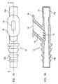
- FIG. 7A is a plan view showing a suction connector 71 in this embodiment; and Figure 7B is a cross-sectional view of the Figure 7A along the line A-A.
- the suction connector 71 includes a fluid passage 72 and a ventilating passage 74 branched in the middle of the fluid passage 71 and having an opening end 73 (opening portion for regulating the suction). Blocking plates 75 are provided inside the ventilating passage 74.
- the fluid passage 72 has a flexible conduit connecting portion 72a to be connected to a flexible conduit (not shown in the drawing) and a suction source connection portion 72b capable of being linked to an extending tube (not shown in the drawing) to be connected to the suction source.
- the basic operation of the suction connector 71 is the same as the suction connector 3 in the First Embodiment.
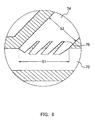
- Figure 8 is an enlarged cross-sectional view showing the blocking plate 75 and the peripheral portion thereof shown in Figure 7.
- S1 in Figure 8 shows a cross section inside the ventilating passage 74 in which the ventilating passage 74 is opened to the fluid passage 72.
- S2 shows a cross section inside the ventilating passage 74, which is perpendicular to the axis of the ventilating passage 74.
- the cross-sectional shape of the ventilating passage 74 is oval as shown in Figure 9.
- Figure 9A shows the shape of the ventilating passage 74 and the blocking plate 75 in the cross section S2; and
- Figure 9B shows the shape of the ventilating passage 74 and the blocking plate 75 in the cross section S1.
- the opening end 73 is provided with a flange 76.
- the stop 76 is provided so that an operator can touch and slide across the opening end 73 so as to regulate the open/close degree. Thereby, it is possible to carry out the fine regulation easily.
- the size of the blocking plates 75 are relatively small as compared with those shown in Figure 2 in the first embodiment. That is, the proportion of the region in which the blocking plates 75 are present in the ventilating passage 74 is rather small. Furthermore, as is apparent from the cross section shown in Figure 8, the plates constituting the blocking plate 75 do not have an overlapped portion ⁇ as shown in Figure 5. The neighboring plates are arranged separately from each other so that the end of the plate at the fluid passage side does not face in line to the end of the plate at the opening end side. Even with such an arrangement, it is possible to exhibit the sufficient function of preventing liquid from scattering.
- the blocking plates 75 can enhance the function of preventing liquid from scattering without adversely affecting the function of releasing a negative pressure.
- the shape of the suction connector was assumed to be the same as that shown in Figure 7 and the narrowest diameter of the fluid passage 72 was set to be 3 mm.
- the dimension of the cross-section S1 and the cross section S2 were set to be those shown in Figure 9.
- the angle of the ventilating passage 74 with respect to the fluid passage 72 was set to be 45 degrees.
- the thickness of the plates constituting the blocking plate 75 was in the range from 0.28 to 0.43 mm; and the length of the ventilating passage 74 in the direction of the axis thereof was set to be 1.5 mm. Furthermore, the same suction connector except that it dose not have the blocking plate 75 was prepared.
- the minimum cross-sectional area of the ventilating passage 74 that is, the area obtained by subtracting the area of the blocking plates from the area of the cross-section S2 when the blocking plate are provided, was 9.9 mm 2 , and the area of the cross section S2 when the blocking plates were not provided was 13.8 mm 2 .
- the evaluation of the effect of preventing liquid from scattering was carried out as follows. First, the suction operation was carried out by putting the tip of the catheter into/from the water 20 times so that water and air are mixed assuming that the catheter is used. In order to measure the scattering amount of the sucked water, a cellophane tape, to which a filter paper had been attached in advance, was prepared and attached to the opening end 73. The total weight of the cellophane tape to which the filter paper had been attached was measured before and after the suction operation. The difference between the measured weights before and after the suction operation was assumed to be the amount of scattering water. The suction pressure was set to be 26.7 kPa.
- the function of releasing a negative pressure was evaluated as follows. The tip of the catheter was fixed in water and suction was carried out with the opening end 73 opened. At this time, the increased height of the liquid surface in the catheter was measured. The measurement value was assumed to be a residual negative pressure value and it was subjected to evaluation. The measurement was carried out at each suction pressure of 20.0, 28.0, 41.3, 61.3 and 93.3 kPa.
- the amount of scattered liquid of the suction connector without the blocking plates is 3-4 times that of the suction connector having blocking plates.
- the residual negative pressure values was higher by 0.01 to 0.03 kPa in the suction connector having blocking plates when the residual negative pressure values were 41.3, 61.3 and 93.3 kPa.
- the suction pressure was 20.0 and 28.0 kPa, there is no difference between both connectors and the residual negative pressure value was 0 Pa. Since the generally used suction pressure is 20.0 to 26.7 kPa for adults and 16.0 to 20.0 kPa for children, the above-mentioned results show that the function of releasing a negative pressure of the suction connector having a blocking plate is practically sufficient.
- the thickness of the blocking plate is the same, it is assumed that the effect of releasing a negative pressure is not changed. Therefore, by adjusting the height of the blocking plate (the length of the ventilating passage in the direction of the axis) in accordance with the usage modes, the function of preventing liquid from scattering can be regulated.
- a catheter of the present invention to which a suction connector is attached, since liquid advancing into a ventilating passage collides with a blocking plate and is caused to return to the fluid passage, liquid can be prevented from flowing out of an opening end of the ventilating passage beyond the blocking plate. Therefore, since the liquid is not attached to the operator's finger pushing on the opening end of the ventilating passage, there is no danger of contamination or infection to the operator, enabling a treatment safely and sanitarily. In addition, the function of releasing a negative pressure can be secured sufficiently. Furthermore, the suction connector according to the present invention has a simple structure and thus can be provided cheaply.
Landscapes
- Health & Medical Sciences (AREA)
- Heart & Thoracic Surgery (AREA)
- Vascular Medicine (AREA)
- Engineering & Computer Science (AREA)
- Anesthesiology (AREA)
- Biomedical Technology (AREA)
- Hematology (AREA)
- Life Sciences & Earth Sciences (AREA)
- Animal Behavior & Ethology (AREA)
- General Health & Medical Sciences (AREA)
- Public Health (AREA)
- Veterinary Medicine (AREA)
- External Artificial Organs (AREA)
- Media Introduction/Drainage Providing Device (AREA)
Abstract
Description
Claims (7)
- A suction connector, comprising a fluid passage having one end to be connected to a conduit and the other end to be connected to a suction source when in use and a ventilating passage branched in the middle of the fluid passage and having an opening end, wherein a blocking plate is disposed at least at a partial region on a fluid passage side inside the ventilating passage, the cross-section of the ventilating passage is divided by the blocking plate into a plurality of regions, and fluid advancing from the fluid passage into the ventilating passage is prevented by the blocking plate from flowing out from the opening end.
- The suction connector according to claim 1, wherein the blocking plates are disposed in the region excluding the proximity of the opening end.
- The suction connector according to claim 1, wherein a plurality of regions on the cross-section of the ventilating passage are divided so that the regions are arranged in the axial direction of the fluid passage.
- The suction connector according to claim 1, wherein the blocking plate is disposed with inclination toward the side to which the conduit is connected with respect to the direction of the fluid passage.
- The suction connector according to claim 1 or 4, wherein the axial direction of the ventilating passage is inclined toward the side to which the conduit is connected with respect to the axial direction of the fluid passage.
- The suction connector according to claim 4, wherein the blocking plate comprises two plates or more and an end of the plate at the fluid passage side and an end of the plate at the opening portion side have an overlapped portion with each other seen from the direction perpendicular to the fluid passage or face in line to each other.
- A suction catheter using a suction connector described in any one of claims 1 to 4, wherein a conduit is connected to one end of the fluid passage of the suction connector.
Applications Claiming Priority (5)
| Application Number | Priority Date | Filing Date | Title |
|---|---|---|---|
| JP30925899 | 1999-10-29 | ||
| JP30925899 | 1999-10-29 | ||
| JP2000283661 | 2000-09-19 | ||
| JP2000283661A JP3534058B2 (en) | 1999-10-29 | 2000-09-19 | Suction connector and suction catheter using the same |
| PCT/JP2000/007654 WO2001030416A1 (en) | 1999-10-29 | 2000-10-30 | Suction connector and suction catheter using the connector |
Publications (3)
| Publication Number | Publication Date |
|---|---|
| EP1226836A1 true EP1226836A1 (en) | 2002-07-31 |
| EP1226836A4 EP1226836A4 (en) | 2005-11-30 |
| EP1226836B1 EP1226836B1 (en) | 2008-03-19 |
Family
ID=26565896
Family Applications (1)
| Application Number | Title | Priority Date | Filing Date |
|---|---|---|---|
| EP00970231A Expired - Lifetime EP1226836B1 (en) | 1999-10-29 | 2000-10-30 | Suction connector and suction catheter using the connector |
Country Status (6)
| Country | Link |
|---|---|
| US (1) | US6986757B1 (en) |
| EP (1) | EP1226836B1 (en) |
| JP (1) | JP3534058B2 (en) |
| CN (1) | CN1182881C (en) |
| DE (1) | DE60038385T2 (en) |
| WO (1) | WO2001030416A1 (en) |
Families Citing this family (13)
| Publication number | Priority date | Publication date | Assignee | Title |
|---|---|---|---|---|
| EP2686030B1 (en) * | 2011-03-14 | 2021-10-20 | Neuro Enterprises, LLC | Self-cleaning surgical suction device |
| US9833207B2 (en) | 2012-08-08 | 2017-12-05 | William Harrison Zurn | Analysis and clearing module, system and method |
| US9962533B2 (en) | 2013-02-14 | 2018-05-08 | William Harrison Zurn | Module for treatment of medical conditions; system for making module and methods of making module |
| USD713027S1 (en) * | 2013-04-22 | 2014-09-09 | Jason P. Adams | Suction probe |
| CN104474597A (en) * | 2014-12-22 | 2015-04-01 | 苏州景联精密机械有限公司 | Sputum aspiration device for pediatrics department |
| CN109069707B (en) | 2016-02-03 | 2021-06-01 | 茵泰勒斯医疗公司 | Suction and Irrigation Devices |
| CN107303398A (en) * | 2016-04-17 | 2017-10-31 | 周星 | Seepage prevention oral care sputum aspirator tube |
| CN107469162B (en) * | 2017-08-28 | 2020-10-27 | 北京工业大学 | High-precision venous drainage device |
| US10702638B2 (en) | 2018-08-31 | 2020-07-07 | Njr Medical, Inc. | Tracheal and pharyngeal suction device |
| CN113350581B (en) * | 2020-03-06 | 2025-09-16 | 江苏邦盛振业医疗器械有限公司 | Sputum aspirator for reducing vacuum residue and manufacturing process |
| AU2021356704A1 (en) | 2020-10-09 | 2023-06-01 | Icu Medical, Inc. | Fluid transfer device and method of use for same |
| CN119386292B (en) * | 2024-11-07 | 2025-10-21 | 杭州市萧山区中医院 | A suction device for surgical debridement |
| CN120361330B (en) * | 2025-06-26 | 2026-02-06 | 湖南省华芯医疗器械有限公司 | Proximal connector of suction catheter, suction catheter and suction endoscope |
Family Cites Families (12)
| Publication number | Priority date | Publication date | Assignee | Title |
|---|---|---|---|---|
| US3933177A (en) * | 1973-10-23 | 1976-01-20 | The Black And Decker Manufacturing Company | Manually controlled air inflator adaptor |
| SE8201137L (en) * | 1982-02-24 | 1983-08-25 | Mediplast Ab | DEVICE FOR SUGAR INSTRUMENTS OR SIMILAR AND WAY TO MANUFACTURE IT |
| US4534542A (en) | 1983-12-05 | 1985-08-13 | Superior Plastic Products Corp. | Suction control device for aspirator system |
| US4951661A (en) * | 1988-06-08 | 1990-08-28 | Thayer Medical Corporation | Quick-connect adapter valve for connecting nebulizer and fluid ventilator hose |
| JPH0277049U (en) | 1988-11-30 | 1990-06-13 | ||
| US5013300A (en) * | 1989-03-09 | 1991-05-07 | Williams James D | Apparatus for suction lipectomy surgery |
| US5076322A (en) * | 1990-10-15 | 1991-12-31 | Pradip Choksi | Vacuum limiting, regulating device |
| JP2567345Y2 (en) | 1991-02-28 | 1998-04-02 | 川澄化学工業株式会社 | Suction connector |
| US5195952A (en) * | 1992-02-25 | 1993-03-23 | Albert Solnit | Noise reducing aspirator |
| DK3295A (en) * | 1995-01-11 | 1996-07-12 | Pharma Plast Int As | Valve for suction catheter, as well as catheter system comprising such a valve |
| JPH1076001A (en) | 1996-09-04 | 1998-03-24 | Top:Kk | Medical connector |
| US6550493B2 (en) * | 2001-06-13 | 2003-04-22 | Baxter International Inc. | Vacuum demand valve |
-
2000
- 2000-09-19 JP JP2000283661A patent/JP3534058B2/en not_active Expired - Fee Related
- 2000-10-27 CN CNB001331795A patent/CN1182881C/en not_active Expired - Fee Related
- 2000-10-30 DE DE60038385T patent/DE60038385T2/en not_active Expired - Lifetime
- 2000-10-30 EP EP00970231A patent/EP1226836B1/en not_active Expired - Lifetime
- 2000-10-30 WO PCT/JP2000/007654 patent/WO2001030416A1/en not_active Ceased
- 2000-10-30 US US10/111,531 patent/US6986757B1/en not_active Expired - Fee Related
Also Published As
| Publication number | Publication date |
|---|---|
| JP2001190656A (en) | 2001-07-17 |
| DE60038385T2 (en) | 2009-03-05 |
| JP3534058B2 (en) | 2004-06-07 |
| EP1226836A4 (en) | 2005-11-30 |
| EP1226836B1 (en) | 2008-03-19 |
| CN1306866A (en) | 2001-08-08 |
| WO2001030416A1 (en) | 2001-05-03 |
| DE60038385D1 (en) | 2008-04-30 |
| CN1182881C (en) | 2005-01-05 |
| US6986757B1 (en) | 2006-01-17 |
Similar Documents
| Publication | Publication Date | Title |
|---|---|---|
| US6986757B1 (en) | Suction connector and suction catheter using the connector | |
| EP0391511B1 (en) | Suction tube for use in surgical operation, particularly for liposuction | |
| EP0864336B1 (en) | Catheter with valve mechanism | |
| EP1019131B1 (en) | Medical fluid infusion and aspiration | |
| EP4717300A2 (en) | Peripheral intravenous catheters having flow diverting features | |
| EP0558879B1 (en) | Disposable inhaler | |
| US7273473B2 (en) | Sleeved catheter having insertion control mechanism | |
| DE69528985T2 (en) | SUCTION SILICONE FOR USE WITH AN ENDOTRACHEAL TUBE | |
| US5423764A (en) | Lavage apparatus | |
| EP0457220A1 (en) | Suction devices | |
| EP0215537B1 (en) | An intubating device | |
| CN102256646A (en) | Valved holding chamber and mask therefor | |
| US4449974A (en) | Body fluid drainage tube | |
| US5542845A (en) | Dental syringe safety sheath with modified duckbill valve | |
| EP3714837B1 (en) | Two-part suction cannula for dental treatment | |
| US10557552B2 (en) | Trough seal | |
| KR200263447Y1 (en) | A Suction Connector Of Catheter For Medical | |
| WO2021091998A1 (en) | Nasopharyngeal airway devices | |
| AU656143B2 (en) | Improved enteral feeding tube | |
| US12576228B1 (en) | Endotracheal tube adapters | |
| JP2026019459A (en) | Medical parts and waste collection devices | |
| JP2024538375A (en) | Medical Cannula | |
| JP3221471U (en) | catheter | |
| JP2001054567A (en) | Suction catheter equipped with opening and closing means | |
| JP2026066818A (en) | Mouthpiece parts and storage bags containing said mouthpiece parts |
Legal Events
| Date | Code | Title | Description |
|---|---|---|---|
| PUAI | Public reference made under article 153(3) epc to a published international application that has entered the european phase |
Free format text: ORIGINAL CODE: 0009012 |
|
| 17P | Request for examination filed |
Effective date: 20020425 |
|
| AK | Designated contracting states |
Kind code of ref document: A1 Designated state(s): AT BE CH CY DE DK ES FI FR GB GR IE IT LI LU MC NL PT SE |
|
| AX | Request for extension of the european patent |
Free format text: AL;LT;LV;MK;RO;SI |
|
| RIC1 | Information provided on ipc code assigned before grant |
Free format text: 7A 61M 1/00 A |
|
| RBV | Designated contracting states (corrected) |
Designated state(s): AT BE CH CY DE ES FR GB IT LI |
|
| A4 | Supplementary search report drawn up and despatched |
Effective date: 20051014 |
|
| 17Q | First examination report despatched |
Effective date: 20060119 |
|
| GRAP | Despatch of communication of intention to grant a patent |
Free format text: ORIGINAL CODE: EPIDOSNIGR1 |
|
| RBV | Designated contracting states (corrected) |
Designated state(s): DE ES FR GB IT |
|
| GRAS | Grant fee paid |
Free format text: ORIGINAL CODE: EPIDOSNIGR3 |
|
| RAP1 | Party data changed (applicant data changed or rights of an application transferred) |
Owner name: JMS CO., LTD. |
|
| GRAA | (expected) grant |
Free format text: ORIGINAL CODE: 0009210 |
|
| AK | Designated contracting states |
Kind code of ref document: B1 Designated state(s): DE ES FR GB IT |
|
| REG | Reference to a national code |
Ref country code: GB Ref legal event code: FG4D |
|
| REF | Corresponds to: |
Ref document number: 60038385 Country of ref document: DE Date of ref document: 20080430 Kind code of ref document: P |
|
| ET | Fr: translation filed | ||
| PG25 | Lapsed in a contracting state [announced via postgrant information from national office to epo] |
Ref country code: ES Free format text: LAPSE BECAUSE OF FAILURE TO SUBMIT A TRANSLATION OF THE DESCRIPTION OR TO PAY THE FEE WITHIN THE PRESCRIBED TIME-LIMIT Effective date: 20080630 |
|
| PLBE | No opposition filed within time limit |
Free format text: ORIGINAL CODE: 0009261 |
|
| STAA | Information on the status of an ep patent application or granted ep patent |
Free format text: STATUS: NO OPPOSITION FILED WITHIN TIME LIMIT |
|
| 26N | No opposition filed |
Effective date: 20081222 |
|
| PG25 | Lapsed in a contracting state [announced via postgrant information from national office to epo] |
Ref country code: IT Free format text: LAPSE BECAUSE OF FAILURE TO SUBMIT A TRANSLATION OF THE DESCRIPTION OR TO PAY THE FEE WITHIN THE PRESCRIBED TIME-LIMIT Effective date: 20080319 |
|
| PGFP | Annual fee paid to national office [announced via postgrant information from national office to epo] |
Ref country code: DE Payment date: 20101027 Year of fee payment: 11 |
|
| PGFP | Annual fee paid to national office [announced via postgrant information from national office to epo] |
Ref country code: GB Payment date: 20101027 Year of fee payment: 11 |
|
| PGFP | Annual fee paid to national office [announced via postgrant information from national office to epo] |
Ref country code: FR Payment date: 20111103 Year of fee payment: 12 |
|
| GBPC | Gb: european patent ceased through non-payment of renewal fee |
Effective date: 20121030 |
|
| REG | Reference to a national code |
Ref country code: FR Ref legal event code: ST Effective date: 20130628 |
|
| PG25 | Lapsed in a contracting state [announced via postgrant information from national office to epo] |
Ref country code: GB Free format text: LAPSE BECAUSE OF NON-PAYMENT OF DUE FEES Effective date: 20121030 Ref country code: DE Free format text: LAPSE BECAUSE OF NON-PAYMENT OF DUE FEES Effective date: 20130501 |
|
| REG | Reference to a national code |
Ref country code: DE Ref legal event code: R119 Ref document number: 60038385 Country of ref document: DE Effective date: 20130501 |
|
| PG25 | Lapsed in a contracting state [announced via postgrant information from national office to epo] |
Ref country code: FR Free format text: LAPSE BECAUSE OF NON-PAYMENT OF DUE FEES Effective date: 20121031 |