EP1226390B1 - Refractory tile system for boiler tube/heat exchanger protection - Google Patents
Refractory tile system for boiler tube/heat exchanger protection Download PDFInfo
- Publication number
- EP1226390B1 EP1226390B1 EP20000914996 EP00914996A EP1226390B1 EP 1226390 B1 EP1226390 B1 EP 1226390B1 EP 20000914996 EP20000914996 EP 20000914996 EP 00914996 A EP00914996 A EP 00914996A EP 1226390 B1 EP1226390 B1 EP 1226390B1
- Authority
- EP
- European Patent Office
- Prior art keywords
- tiles
- boiler
- wall
- tile
- fastener system
- Prior art date
- Legal status (The legal status is an assumption and is not a legal conclusion. Google has not performed a legal analysis and makes no representation as to the accuracy of the status listed.)
- Expired - Lifetime
Links
- 238000007667 floating Methods 0.000 claims abstract description 21
- 239000004570 mortar (masonry) Substances 0.000 claims abstract description 21
- 230000004888 barrier function Effects 0.000 claims abstract description 20
- 239000011248 coating agent Substances 0.000 claims abstract description 11
- 238000000576 coating method Methods 0.000 claims abstract description 11
- 239000000356 contaminant Substances 0.000 claims abstract description 4
- 238000005260 corrosion Methods 0.000 claims description 27
- 230000007797 corrosion Effects 0.000 claims description 26
- 239000000463 material Substances 0.000 claims description 15
- 238000000034 method Methods 0.000 claims description 6
- 239000012528 membrane Substances 0.000 claims description 5
- HBMJWWWQQXIZIP-UHFFFAOYSA-N silicon carbide Chemical compound [Si+]#[C-] HBMJWWWQQXIZIP-UHFFFAOYSA-N 0.000 claims description 5
- 229910019142 PO4 Inorganic materials 0.000 claims description 2
- 230000002093 peripheral effect Effects 0.000 claims description 2
- 239000010452 phosphate Substances 0.000 claims description 2
- 125000002467 phosphate group Chemical group [H]OP(=O)(O[H])O[*] 0.000 claims description 2
- 238000007493 shaping process Methods 0.000 claims description 2
- 238000004513 sizing Methods 0.000 claims description 2
- 230000007246 mechanism Effects 0.000 abstract description 11
- WWYNJERNGUHSAO-XUDSTZEESA-N (+)-Norgestrel Chemical compound O=C1CC[C@@H]2[C@H]3CC[C@](CC)([C@](CC4)(O)C#C)[C@@H]4[C@@H]3CCC2=C1 WWYNJERNGUHSAO-XUDSTZEESA-N 0.000 abstract 1
- 238000012546 transfer Methods 0.000 description 12
- 239000002253 acid Substances 0.000 description 9
- 230000000694 effects Effects 0.000 description 9
- 238000009434 installation Methods 0.000 description 8
- 238000012360 testing method Methods 0.000 description 8
- 239000010813 municipal solid waste Substances 0.000 description 7
- 230000035882 stress Effects 0.000 description 7
- XLYOFNOQVPJJNP-UHFFFAOYSA-N water Substances O XLYOFNOQVPJJNP-UHFFFAOYSA-N 0.000 description 7
- 238000004458 analytical method Methods 0.000 description 6
- 239000007789 gas Substances 0.000 description 6
- 230000003647 oxidation Effects 0.000 description 6
- 238000007254 oxidation reaction Methods 0.000 description 6
- 230000008901 benefit Effects 0.000 description 5
- 238000013459 approach Methods 0.000 description 4
- 238000006073 displacement reaction Methods 0.000 description 4
- 230000006855 networking Effects 0.000 description 4
- 230000035515 penetration Effects 0.000 description 4
- 238000002485 combustion reaction Methods 0.000 description 3
- 238000005336 cracking Methods 0.000 description 3
- 239000010935 stainless steel Substances 0.000 description 3
- 229910001220 stainless steel Inorganic materials 0.000 description 3
- 150000007513 acids Chemical class 0.000 description 2
- 238000004519 manufacturing process Methods 0.000 description 2
- 230000001681 protective effect Effects 0.000 description 2
- 239000012858 resilient material Substances 0.000 description 2
- 229910010271 silicon carbide Inorganic materials 0.000 description 2
- 238000013519 translation Methods 0.000 description 2
- 235000001674 Agaricus brunnescens Nutrition 0.000 description 1
- 229910000851 Alloy steel Inorganic materials 0.000 description 1
- 230000009471 action Effects 0.000 description 1
- 238000007792 addition Methods 0.000 description 1
- 229910010293 ceramic material Inorganic materials 0.000 description 1
- 239000000567 combustion gas Substances 0.000 description 1
- 230000001186 cumulative effect Effects 0.000 description 1
- 230000002939 deleterious effect Effects 0.000 description 1
- 238000005516 engineering process Methods 0.000 description 1
- 230000003628 erosive effect Effects 0.000 description 1
- 238000013213 extrapolation Methods 0.000 description 1
- 239000000446 fuel Substances 0.000 description 1
- 230000005484 gravity Effects 0.000 description 1
- 230000006872 improvement Effects 0.000 description 1
- 230000000977 initiatory effect Effects 0.000 description 1
- 239000002184 metal Substances 0.000 description 1
- 230000004048 modification Effects 0.000 description 1
- 238000012986 modification Methods 0.000 description 1
- SNICXCGAKADSCV-UHFFFAOYSA-N nicotine Chemical compound CN1CCCC1C1=CC=CN=C1 SNICXCGAKADSCV-UHFFFAOYSA-N 0.000 description 1
- 230000000737 periodic effect Effects 0.000 description 1
- 238000010248 power generation Methods 0.000 description 1
- 230000001737 promoting effect Effects 0.000 description 1
- 239000011819 refractory material Substances 0.000 description 1
- 230000004044 response Effects 0.000 description 1
- 150000003839 salts Chemical class 0.000 description 1
- 230000008646 thermal stress Effects 0.000 description 1
- 239000002699 waste material Substances 0.000 description 1
Images





Classifications
-
- F—MECHANICAL ENGINEERING; LIGHTING; HEATING; WEAPONS; BLASTING
- F22—STEAM GENERATION
- F22B—METHODS OF STEAM GENERATION; STEAM BOILERS
- F22B37/00—Component parts or details of steam boilers
- F22B37/02—Component parts or details of steam boilers applicable to more than one kind or type of steam boiler
- F22B37/10—Water tubes; Accessories therefor
Definitions
- the present invention is directed to a boiler, particularly to refractory tube blocks which protect metallic waterwall tubes from hot and highly corrosive furnace gases, while at the same time maintaining good heat conductivity.
- Refractory tiles have long been used for the protection of boiler walls in waste incinerators and other heat exchanger applications.
- the primary function of the tiles has been to shield the steel alloy boiler walls, which typically include waterwall tubes and membranes or webs disposed therebetween, from the temperature, erosion, and corrosion by acid vapor attack associated with boiler operation. These conditions are generated by the combustion process occurring within the boiler.
- Municipal solid waste (MSW) facilities incinerate trash and garbage in furnaces at temperatures of up to about 1400°C.
- water is passed through metallic waterwall tubes adjacent to the furnace and converted to steam by the high temperatures.
- the steam produced in the tube assembly is then used to power a turbine-driven electric generator.
- the MSW plant also produces gaseous products which, if allowed to contact the metal wall, would chemically attack the walls.
- the purpose of the refractory tiles has been to prevent direct attack of the walls by gaseous products and still allow the tubes to be sufficiently heated to efficiently generate steam. The primary purpose of the tiles is thus to extend tube wall lifetime expectancy.
- Refractory tiles for boiler tube protection have traditionally been fabricated from a material such as silicon carbide (SiC). These tiles typically are provided with a substantially planar face with a contoured back surface sized and shaped to match the contour of the tube wall. Such tiles generally have been fabricated as a variant of one of three configurations, namely bolted tiles; hanging tiles, such as disclosed in U.S. Patent No. 4,768,447 to Roumeguere; and modified hanging tiles also known as slotted or T-slotted tiles such as disclosed in U.S. Patent No. 5,243,801 to Aiken, et al. and in WO 97/09577 to Zampell Advanced Refractory Technologies, Inc.
- the U.S. 4,768,447, U.S. 5,243,801 and WO 97/09577 references are fully incorporated by reference herein.
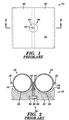
- bolted tiles 10 are generally provided with a square or rectangular face 12 adapted for orientation towards an interior of the boiler.
- a hole penetrates through the thickness of the tile in the approximate center of the face 12.
- a countersunk region 34 typically exists within the hole or bore 30 to act as a seat for a nut 26.
- a stud or threaded bolt 24 is welded to a membrane region 16 between two tubes 18 in the boiler wall 62.
- the contoured back surface 14 of the tile 10 includes accurate portions 20 sized and shaped to receivably match the profile of the tube wall 19 and allow for close contact therewith.
- the tile is installed by fitting the stud through the hole and securing the tile in position with a washer 28 and nut 26 threaded onto the stud.
- a cap (not shown) is then typically mortared in place over the hole to minimize the amount of gas that can flow through clearance between the standard hole to the backside of the tile.
- a layer of mortar (not shown) is typically applied between the tile and the wall 62, and between adjacent tiles, to form a rigid structure which serves to help secure the tile in position and to substantially prevent gas from flowing between and/or behind the tiles.
- An advantage of using a bolted tile configuration is that the tiles are relatively easy to install and may be installed on substantially any surface of the boiler, including vertical and overhanging surfaces.
- a disadvantage of such bolted tiles is associated with tile failures. These tiles usually have a 2 to 4 year life expectancy due to stud failure. When the studs fail, the tiles tend to fall off of the walls, leaving the boiler tubes exposed to the incinerator atmosphere. The cause of failure in the studs was previously believed to have been due to high temperature acid corrosion. In particular, it was believed that the acids penetrated the tile through the stud hole to attack the stud. The corrosion was believed to be severe on the stud due to its high operating temperature (believed to be 1000°C or more). Also, cracking of the tiles was a common occurrence, and believed to have been generated by overstressing the stud.
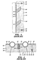
- hanging tiles 45 typically utilize an anchor/hook or short stud 37 to hang the tile on the membrane 16 of the boiler wall 62, with gravity utilized to maintain the tile in close proximity to the boiler wall 62 for good heat transfer.
- This tile 45 is a modification of the bolted tile in that one or more holes 30' project from the back surface 14' of the tile toward the hot face 12, but do not fully penetrate the hot face. This provides the tile with a closed face, to theoretically improve acid corrosion resistance.
- a layer of mortar (not shown) is typically installed between the tile 45 and the boiler wall 62, as well as between adjacent tiles to form a rigid, substantially gas and ash impermeable structure.
- a variation of this hanging tile arrangement utilizes the tiles 45 in conjunction with an air sweep system.
- no mortar is installed behind the tiles to leave a gap between the tiles and the boiler wall.
- a flow of air is fed through this gap to help minimize acid corrosion of the wall.
- An advantage of hanging tiles in general is the relative ease of installation and replacement.
- a disadvantage of such hanging tile arrangements is that the tiles generally cannot be installed on non-vertical walls, as the tiles tend to fall off their anchors. Also, tiles have been known to lift off of their anchors during operation due to thermal expansion, etc.
- the above described air sweep system tends to disadvantageously increase the expense of the tile system relative to configurations utilizing mortar. Heat transfer between the tiles and wall also may be disadvantageously reduced due to the insulative (i.e., relatively low thermal conductivity) characteristic of air layers.
- modified hanging tiles 50 have been developed in an attempt to address the drawbacks associated with the hanging tiles becoming dislodged from their anchors or hooks.
- modified configurations are commonly known as mushroom bolt, tube-welded fin anchor, and T-slot tiles.
- These tiles 50 are typically hybrids of bolted tiles and hanging tiles, incorporating a closed tile face 12' with an anchor 52 that has a substantially T-shaped profile, to effectively capture the tiles and allow them to be installed on both vertical and overhanging surfaces.
- These tiles 50 are generally installed with a layer of mortar between the tile and the boiler wall, as well as between adjacent tiles.
- the purpose of the mortar is to help secure the tiles by providing a rigid attachment and to provide a barrier to resist penetration of ash and corrosive gas between and behind the tiles.
- modified tiles 50 may be installed on nominally any boiler surface. Disadvantages of the tiles 50 include difficulty of manufacture since they incorporate a blind (i.e., discontinuous) slot 54 projecting laterally into the tile from an edge thereof. Also, the tiles may be physically weaker due to the complexity of the blind slots 54. Moreover, individual tiles generally cannot be replaced without removing a entire row of tiles.
- a blind slot 54 projecting laterally into the tile from an edge thereof.
- the tiles may be physically weaker due to the complexity of the blind slots 54.
- individual tiles generally cannot be replaced without removing a entire row of tiles.
- many of the approaches discussed hereinabove utilize a fibrous compressible material or mortar at periodic tile intervals to serve as expansion joints.
- such material may be used every 7 to 15 tiles in a manner familiar to those skilled in the art of masonry (i.e., such as commonly utilized in fabrication of concrete sidewalks, etc.)
- These joints tend to disadvantageously permit the passage of acids and other corrosive materials therethrough, to enable corrosion of the underlying boiler wall.
- the useful life of tile systems having such expansion joints have not been shown to be appreciably greater than similar tile configurations not having such expansion joints.
- EP-A-0 854 321 describes a boiler water pipe protecting refractory structure comprising a refractory interposed between a boiler water pipe and a combustion gas.
- the water pipe protecting refractory structure is provided as a refractory structure capable of reducing thermal stress without increasing the wall thickness of refractory blocks, and improving the durability of mounting members by preventing the occurrence of high-temperature corrosion thereof, and has a high heat transfer efficiency.
- this structure is provided with a refractory block, which has an arcuate portion and a connecting portion engaged at inner circumferences thereof with the boiler water pipe, and a locking recess and a locking projection formed on the boiler water pipe, respectively, as fixing means for detachably engaging the refractory block and boiler water pipe with each other.
- EP-A-0 656 508 refers to a protective wall structure for protecting boiler tubing in facilities using refuse as a fuel source to produce steam for electrical power generation.
- the protective wall shall structure includes an array of shielding tiles, heat transfer bonding material, and elongated compressible material.
- the shielding tiles include a front surface facing the interior combustion zone of the facility, a rear surface facing the boiler tubes, and a plurality of sidewall surfaces.
- the heat transfer bonding material is positioned between the boiler tubes and the rear surfaces of the shielding tiles to permit heat transfer and create a bond between the boiler tubes and the shielding tiles.
- the elongated compressible material is positioned between the sidewall perimeter surfaces of adjacent shielding tiles to provide an expansion joint. This permits relative expansion between adjacent shielding tiles without cracking upon an increase in temperature in the interior combustion zone.
- the present invention refers to a boiler according to independent claim 1 as well as to a method for assembling a refractory tile system for use on a wall of a boiler.
- a significant aspect of the present invention is the recognition of the problem responsible for many of the failures of the prior art systems. It was recognized that these failures were generated by both bowing of individual tiles (as used herein, “micro-scale” bowing) and collective bowing of multiple tiles (as used herein, “networked” or “macro-scale” bowing) as shown in Fig. 8.
- micro-scale bowing generates forces F which transfer through the rigid mortar (not shown) to adjacent tiles to thus generate a macro-scale bowing effect.
- the macro-scale bowing applies sufficient tensile stress to the studs to cause failure.
- any significant dimensional instability of the tiles was primarily limited to thermal expansion generated by exposure to elevated boiler temperatures.
- any bowing was limited to individual tiles.
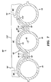
- the present invention is based on the recognition that thermal gradients experienced by individual tiles during boiler operation (i.e., the difference between the temperature at the hot face 112' and the back 114' as shown, for example, in Fig. 7) were greater than previously suspected, and exerted a greater influence on the dimensional instability of the tiles than the aforementioned thermal expansion. It was then realized that bowing generated by the thermal gradient tended to transfer stresses through the rigid mortar disposed between adjacent tiles to effectively magnify the effects of individual tile bowing as a function of the square of the length of the tile network.
- oxidation on the hot face on the tiles occurring over time creates "hot spots" which tend to exacerbate the temperature gradient across the tile to further contribute to the micro-scale bowing effect.
- the macro-scale bowing serves to accelerate the oxidation, thus initiating a self-perpetuating cycle that serves to accelerate the decay of the tiles.
- optimum operating temperature of the hot face of SiC tiles may be approximately 500 to 600 degrees C. Oxidation at this temperature has been found to be minimal and to not substantially affect tile life. However, it has been found that oxidation progresses rapidly in the event the hot face reaches or exceeds about 750 degrees C and continues to accelerate rapidly as the temperature increases further.
- An aspect of the present invention was thus the recognition that the macro-scale bowing serves to separate the tiles from the boiler wall, forming an air gap which generally reduces the heat transfer from the back of the tile to the wall. This decrease in heat transfer effectively increases the temperature at the hot face beyond the preferred operating temperature range.
- the macro-scale bowing eventually has the effect of raising the hot face temperature to the oxidation promoting temperature of 750 degrees C or more. The oxidation in turn, tends to further increase the temperature gradient which as discussed hereinabove, tends to further exacerbate the macro-scale bowing, thus forming a self-perpetuating, deleterious cycle.
- Initial steps in developing the present invention included completion of a first finite element model (FEM) of a conventional 18cm x 18cm bolted tile to assess the cause of cracking in the tiles during operation.
- FEM finite element model
- Failed studs were then retrieved from an incinerator. Analysis of the studs revealed that they had been stretched approximately 6mm prior to failure. This indicated that the studs were placed under a tensile load, and thus were not failing by acid corrosion alone, but rather by stress-corrosion. It was thus determined to examine the cause of the stress on the studs.
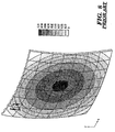
- a third finite element model was initiated to study the phenomenon of tile bowing and tensile stress.
- the first FEM indicated that bowing of individual tiles, or micro-scale bowing, occurred due to thermal gradients. This bowing, however, was of insufficient magnitude (0.3 mm) to have caused the 6mm deformation observed in the studs.
- a refractory tile system for use on a wall of a boiler includes a plurality of tiles having a floating fastener system engagable with the wall to maintain the tiles in spaced, movable relation to one another as well as in spaced movable relation to the wall.
- the tiles are sized and shaped to provide a gap between adjacent ones of the tiles, the gap being sufficient to accommodate dimensional changes of the tiles exhibited during exposure to operational temperatures of the boiler.
- a corrosion barrier is disposed between the tiles and the wall.
- the corrosion barrier is a coating applied to the tube wall and the coating is adapted to adhere to the wall a to be free from adherence the tiles.
- a refractory tile system for use on a wall of a boiler includes a plurality of tiles disposed on the wall in spaced, movable relation to one another.
- the tiles are sized and shaped to provide a gap between adjacent ones of the tiles, the gap being sufficient to substantially prevent macro-scale bowing of the tiles during exposure to operational temperatures of the boiler.
- a corrosion barrier is disposed between the tiles and the wall to substantially prevent corrosion of the wall.
- a method for increasing the useful life of a wall of a boiler includes the steps of:
- axial when used in connection with an element described herein, shall refer to a direction relative to the element, which is substantially parallel to the central axis a of tube 18 (i.e., Fig. 7) when the element is disposed in engagement with a tube 18 as shown in Figs. 6, 7, 10 and 14.
- transverse refers to a direction substantially orthogonal to the axial direction.
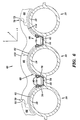
- a refractory tile system 60 includes a barrier layer coating 61 applied to the wall 62 (i.e., membrane 16 and tube wall 19) of a boiler of an incinerator or heat exchanger.
- the barrier layer 61 is adapted to provide acid and salt corrosion resistance at the normal operating temperatures of the boiler.
- An example of such a coating is a phosphate bonded SiC barrier layer such as PC-1022TM available from Norton Company of Worcester, Massachusetts.
- this material provides relatively good corrosion resistance and thermal conductivity.
- Refractory tiles 66 are then fastened to the tube wall 62 in superposed relation with the wall 62 utilizing a floating attachment mechanism 68.
- the tiles 66 are fabricated from any suitable refractory material known to those skilled in the art, such as, for example silicon carbide (SiC) or other ceramic materials capable of withstanding the temperatures (as high as approximately 1400°C) experienced within the boiler of a MSW incinerator/heat exchanger, and the like.
- SiC silicon carbide
- other ceramic materials capable of withstanding the temperatures (as high as approximately 1400°C) experienced within the boiler of a MSW incinerator/heat exchanger, and the like.
- the floating attachment mechanism 68 provides the tiles 66 with a relatively high degree of freedom of movement relative to the tube wall 62 to accommodate micro-scale bowing of the tile.
- the micro-scale bowing has been found to be generated by the relatively large temperature gradient (typically about 200 to 600°C or more) experienced by such tiles.
- this temperature gradient has been found to have a substantially greater effect on the dimensional instability of the tiles than the elevated temperature per se, particularly in light of the networking effect in which bowing increases as a square of length of the tile array.
- Each tile 66 is effectively isolated from adjacent tiles by providing a predetermined gap 70 therebetween of sufficient size to effectively prevent macro-scale bowing which has been found to be generated by networking. As shown in Fig. 9, this networking phenomena is generated by the pressure or force F exerted by the tiles upon one another through the rigid mortar (not shown) when micro-scale bowed.
- the gap 70 is preferably formed by contoured peripheral edges 72 which are sized and shaped to form a spaced, shiplapped joint between adjacent tiles 66.
- This shiplapped configuration advantageously serves to provide an obstructed line-of-sight between the tiles to inhibit penetration of ash or other contaminants through the gap 70 during operation of the boiler.
- a compressible fibrous mortar (not shown) may be disposed in the gap or channel 70 between each adjacent tile to further inhibit ash or other contaminant penetration.
- An example of such a suitable compressible fibrous mortar is known as Topcoat 2600TM available from Unifrax Corporation of Niagara Falls, New York.
- the gaps 70 are sized in combination with the known compressibility of the particular compressible mortar selected, so as to maintain any force transfer between tiles at a magnitude low enough to substantially prevent the occurrence of macro-scaled bowing when the individual tiles are disposed in their maximum micro-scale bowed condition.
- floating attachment mechanism 68 includes rails 74 having a plurality of flexible arms 76 with convex terminal ends 78 adapted to engage similarly sized recesses 80 disposed in the tiles 66. Arms 76 are thus biased into releasable engagement with tile 66 to facilitate installation and removal thereof. Moreover, the resiliency of the arms 76 serves to fasten the tile 66 to the wall 62 in a manner which permits the tile 66 to move or "float" relative to the wall 62 in response to dimensional changes of the tile 66 generated by thermal gradients and elevated mean temperatures.
- the floating attachment mechanism 68 enables the tile 66 to move with at least three degrees of freedom (i.e., along three mutually orthogonal axes x, y and z, as shown) relative to the wall 62. Moreover, in addition to translation along the x, y and z axes, the tile may rotate around a tube 18 and/or bow towards or away from a tube 18.
- the rail 74, including arm 76 and convex terminal end 78 are preferably fabricated from a flexible, corrosion resistant material, such as stainless steel.
- the face 112 of the tile 66 may be provided with a contoured geometry which substantially matches the contour of the wall 62 to provide the tile with a relatively uniform thickness t.
- FIG. 7 an alternate embodiment of the present invention is shown as tile system 60'.
- This embodiment is substantially similar to the tile system 60 shown in Fig. 6, while utilizing a substantially planar face 112' and an alternate floating engagement mechanism 68'.
- this fastener system 68' is in many respects similar to fastener system 68 of Fig. 6, though utilizing approximately 50 percent fewer arms 76'.
- floating mechanism 68 and 60' have been shown, it should be recognized by those skilled in the art that substantially any mounting mechanism capable of securing a tile to a wall 62 of a boiler in a manner which permits the tile to expand and/or bow on a micro-scale without generating the macro-bowing effect as set forth hereinabove, may be utilized without departing from the spirit and scope of the present invention.
- a rigid mounting arrangement may be used in lieu of the flexible arms 76 and 76', as long as sufficient clearance is provided between the mounting hardware and the tile to enable the aforementioned dimensional changes to occur nominally without applying excessive force or stress to the mounting hardware and/or adjacent tiles.
- One example of such an alternate arrangement may include provision of one or more pins 82 (shown in phantom) fabricated from stainless steel or the like, which are insertable into substantially oversized bores 84 (shown in phantom) disposed within in the tile and which extend substantially parallel to the tile face 112.
- the pin 82 is in turn, secured to the wall 62 in any convenient manner known to those skilled in the art, (not shown). In this manner, the tile may be secured to the wall 62 with sufficient clearance to effectively "float" relative to the wall as discussed hereinabove.
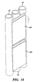
- tile system 60 is substantially similar to the tile systems 60 and 60' shown in Figs. 6 and 7, while using an alternate floating engagement mechanism 68".
- this fastener system 68" is in many respects similar to fastener system 68' of Fig. 7, though the arms 76" are substantially "C” shaped for engagement with substantially semi-cylindrical slots or recesses 80" of the tile 66" as shown.
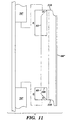
- the slots 80" of tile 66" include upper slots 81 and lower slots 83, which extend axially inward from upper and lower edges 116 and 118, respectively, of tile 66".
- the upper slot 81 preferably extends an axial distance d1 from upper edge 116 that is greater than axial distance d2 of lower slot 83, to facilitate installation of the tile 66" as discussed hereinbelow.
- the upper and lower surfaces 116 and 118 are chamfered, preferably at an angle ⁇ of approximately 30 to 60 degrees, at their intersection with the slots 81 and 83 to further facilitate installation of the tiles 66" as discussed below. In a preferred embodiment, angle ⁇ is approximately 45 degrees as shown.
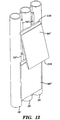
- a tile 66" is installed by placing the upper surface 116 of the tile between the upper and lower arms 76", in substantial axial alignment therewith. This orientation may be accomplished by disposing a portion of the upper surface 116 in surface-to-surface engagement with the tubes 18 as shown.
- the surface 116 of tile 66" is moved axially upwards as indicated by arrow a , while the lower surface 118 is pivoted closer to the tubes 18 as shown by arrow b . This action serves to slide the upper slot 81 (Fig. 11) into receiving engagement with one set of (i.e., the uppermost) arms 76" as shown.
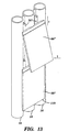
- the tile then may be translated axially towards an adjacent pre-installed tile 66" (i.e., in direction c ) to receivably engage lower arms 76" within lower slots 83 (Fig. 11).
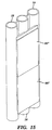
- This translation preferably continues until the lower arms 76" engage the proximal end 120 (Fig. 11) of the slots 83.
- the adjacent tiles 66" will be disposed in their desired spaced, shiplapped orientation as shown in Fig. 15, to complete the installation. Additional tiles 66" (not shown) then may be installed in a similar manner.
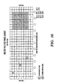
- FIG. 16 A series of conventional bolted tiles of the general type shown in Figs. 1 and 2 were installed in a furnace in a pattern as shown in Fig. 16.
- Tiles labeled A, B, C, and D were instrumented with LVDTs (linear variable-displacement transducers) to measure the displacement of these tiles away from the tube walls during normal furnace operation.
- tiles B and D were located in a tile array portion that included a conventional flexible mortar (the above-referenced Topcoat 2600TM) between adjacent tiles.
- the output of the LVDTs indicate that the instrumented tiles were displaced nearly simultaneously with one another, providing evidence that macroscale bowing was taking place. (The differences in displacement magnitude indicated by the plots were apparently due to variations in location of the LVDTs within the tiles.)
- An array of tiles of the present invention was mounted in a boiler for test.
- the tiles were configured and mounted in the boiler in a manner substantially as shown and described hereinabove with respect to Fig. 7, including use of a barrier material between the boiler wall and the tiles, and Topcoat 2600TM between adjacent tiles.
- Selected tiles indicated as A, B, C, D, E, and G were instrumented with LVDTs in the manner described in Example 1.
- the output of these LVDTs show that the tiles were displaced independently from one another, in a manner contrary to that shown in Example 1.
- attachment mechanisms 68, 68' and 68" enable the tiles 66, 66' and 66" to move or "float" relative to the wall 62, the skilled artisan will recognize that the mechanisms 68, 68' and 68" preferably maintain the tile 66 as close as possible to the surface of the tube 18 to maximize heat transfer through the tile 66 to the tube.
- a conventional bolted tile fastener arrangement as also discussed hereinabove may be modified to provide additional clearance between the stud and bore to permit the tile to float relative to the wall to thus be usable in combination with the corrosion barrier and the gap between adjacent tiles of the present invention.
Landscapes
- Engineering & Computer Science (AREA)
- Physics & Mathematics (AREA)
- Thermal Sciences (AREA)
- Mechanical Engineering (AREA)
- General Engineering & Computer Science (AREA)
- Furnace Housings, Linings, Walls, And Ceilings (AREA)
- Protection Of Pipes Against Damage, Friction, And Corrosion (AREA)
- Chimneys And Flues (AREA)
Abstract
Description
Also, tiles have been known to lift off of their anchors during operation due to thermal expansion, etc. Moreover, the above described air sweep system tends to disadvantageously increase the expense of the tile system relative to configurations utilizing mortar. Heat transfer between the tiles and wall also may be disadvantageously reduced due to the insulative (i.e., relatively low thermal conductivity) characteristic of air layers.
Additionally, the useful life of tile systems having such expansion joints have not been shown to be appreciably greater than similar tile configurations not having such expansion joints.
These blisters were approximately 10 tiles by 10 tiles in area, and were displaced into the boiler.
Claims (25)
- A boiler, comprising:characterized in thata wall (62);a plurality of tiles (66; 66'; 66") having a floating fastener system (68; 68'; 68") engagable with the wall (62) to maintain said tiles (66; 66'; 66") in spaced, movable relation to one another, and wherein said fastener system (68; 68'; 68") maintains said tiles (66; 66'; 66") in spaced, movable relation to the wall (62);said tiles (66; 66'; 66") being sized and shaped to provide a gap (70; 70') between adjacent ones of said tiles (66; 66'; 66"), said gap (70; 70') being sufficient to accommodate dimensional changes of said tiles (66; 66'; 66") exhibited during exposure to operational temperatures of the boiler; anda corrosion barrier disposed between said tiles (66; 66'; 66") and said wall (62),said corrosion barrier is a coating (61) applied to the tube wall (62) and the coating (61) is adapted to adhere to the wall (62) and to be free from adherence to said tiles (66; 66'; 66").
- The boiler of claim 1, wherein said tiles (66; 66'; 66") are sized and shaped to provide a gap between at least a portion of said tiles (66; 66'; 66") and the tube wall (62) sufficient to accommodate said dimensional changes.
- The boiler of claim 1, wherein said gaps (70; 70') are sufficient to accommodate dimensional changes of said tiles (66; 66'; 66") due to exposure to a mean temperature gradient experienced during operation of the boiler.
- The boiler of claim 3, wherein said temperature gradient is within a range of about 500 to 1400 degrees C.
- The boiler of claim 4, wherein said tiles (66; 66'; 66") are maintained close enough to the wall (62) of the boiler to maintain said temperature gradient within said range of about 200-600 degrees C.
- The boiler of claim 5, wherein at least a portion of said tiles (66; 66'; 66") is maintained in superimposed contact with at least a portion of said corrosion barrier, and said corrosion barrier is maintained in superimposed contact with at least a portion of the wall (62).
- The boiler of claim 1, wherein said floating fastener system (68; 68'; 68") comprises a tab disposed on one of said wall (62) and said tiles (66; 66'; 66"), and a receptacle disposed on an other of said wall (62) and said tiles (66; 66'; 66"), said member and said receptacle being adapted for mutual engagement with sufficient clearance to maintain said tiles (66; 66'; 66") in said movable relation.
- The boiler of claim 7, wherein said floating fastener system (68; 68'; 68") comprises a hanging tile system.
- The boiler of claim 7, wherein said floating fastener system (68; 68'; 68") comprises a T-slotted tile system.
- The boiler of claim 1, wherein said floating fastener system (68; 68'; 68") comprises a tab disposed on one of said wall (62) and said tiles (66; 66'; 66"), and a receptacle disposed on an other of said wall (62) and said tiles (66; 66'; 66"), said member and said receptacle being adapted for mutual engagement with sufficient resiliency to maintain said tiles (66; 66'; 66") in said movable relation.
- The boiler of claim 1, wherein said receptacle comprises at least one slot (81, 83), said at least of slot (81, 83) extending in an axial direction.
- The boiler of claim 11, wherein said at least one slot (81, 83) extends inwardly from an edge of said tile (66"), said edge being chamfered relative to the edge of said tile (66").
- The boiler of claim 12, wherein said at least one slot comprises first and second slots extending inwardly from opposite edges of said tile, said first slot extending approximately twice as far as said second slot from respective opposite edges.
- The boiler of claim 12, wherein said chamfer extends approximately 30 to 60 degrees relative to a transverse direction.
- The boiler of claim 1, wherein said floating fastener system (68; 68'; 68") provides said tiles (66; 66'; 66") with at least one degree of freedom of movement relative to the wall (62).
- The boiler of claim 15, wherein said floating fastener system (68; 68'; 68") provides said tiles (66; 66'; 66") with at least two degrees of freedom of movement relative to the wall (62).
- The boiler of claim 15, wherein said floating fastener system (68; 68'; 68") provides said tiles (66; 66'; 66") with at least three degrees of freedom of movement relative to the wall (62).
- The boiler of claim 1, further comprising a compressible material disposed in said gap (70; 70').
- The boiler of claim 18, wherein said compressible material inhibits passage of contaminants into said gap (70; 70').
- The boiler of claim 19, wherein said compressible material comprises a fibrous mortar.
- The boiler of claim 1, wherein said coating comprises a membrane (61).
- The boiler of claim 21, wherein said coating (61) comprises phosphate bonded silicon carbide (SiC).
- The boiler of claim 1, wherein said tiles (66; 66'; 66") further comprise peripheral surfaces sized and shaped to form a spaced, shiplapped joint between said adjacent ones of said tiles (66; 66'; 66").
- The boiler of claim 4, wherein said mean temperature is within a range of about 750 to 1200 degrees C.
- A method for assembling a refractory tile system (60; 60'; 60") for use on a wall (62) of a boiler, said method comprising the steps of:characterized by the further steps(a) providing a plurality of tiles (66; 66'; 66") having a floating fastener system (68; 68'; 68") engagable with the wall (62) to maintain said tiles (66; 66'; 66") in spaced, movable relation to one another, and wherein said fastener system (68; 68'; 68") maintains said tiles (66; 66'; 66") in spaced, movable relation to the wall (62);(b) sizing and shaping said tiles (66; 66'; 66") to provide a gap (70; 70') between adjacent ones of said tiles (66; 66'; 66"), said gap (70; 70') being sufficient to accommodate dimensional changes of said tiles (66; 66'; 66") exhibited during exposure to operational temperatures of the boiler;(c) disposing a corrosion barrier on the wall (62), which corrosion barrier is a coating (61) adhering to the wall (62) while being free from adherence to the tiles (66; 66'; 66"); and(d) engaging the floating fastener system (68; 68'; 68") with the wall (62), wherein the tiles (66; 66'; 66") are superposed with the wall (62) and the corrosion barrier is disposed therebetween.
Applications Claiming Priority (6)
| Application Number | Priority Date | Filing Date | Title |
|---|---|---|---|
| 1998-05-21 | |||
| US12516099P | 1999-03-19 | 1999-03-19 | |
| US125160P | 1999-03-19 | ||
| US09/526,331 US6267066B1 (en) | 2000-03-15 | 2000-03-15 | Refractory tile system for boiler tube/heat exchanger |
| US526331 | 2000-03-15 | ||
| PCT/US2000/007135 WO2000057106A1 (en) | 1999-03-19 | 2000-03-17 | Refractory tile system for boiler tube/heat exchanger protection |
Publications (2)
| Publication Number | Publication Date |
|---|---|
| EP1226390A1 EP1226390A1 (en) | 2002-07-31 |
| EP1226390B1 true EP1226390B1 (en) | 2004-10-27 |
Family
ID=26823324
Family Applications (1)
| Application Number | Title | Priority Date | Filing Date |
|---|---|---|---|
| EP20000914996 Expired - Lifetime EP1226390B1 (en) | 1999-03-19 | 2000-03-17 | Refractory tile system for boiler tube/heat exchanger protection |
Country Status (7)
| Country | Link |
|---|---|
| EP (1) | EP1226390B1 (en) |
| JP (1) | JP3689000B2 (en) |
| KR (1) | KR100469549B1 (en) |
| AT (1) | ATE280926T1 (en) |
| BR (1) | BR0009117A (en) |
| CA (1) | CA2372168C (en) |
| DE (1) | DE60015378T2 (en) |
Families Citing this family (5)
| Publication number | Priority date | Publication date | Assignee | Title |
|---|---|---|---|---|
| FR2882812B1 (en) * | 2005-03-07 | 2007-05-25 | Saint Gobain Ct Recherches | REFRACTORY TILE, IN PARTICULAR FOR A GASIFIER. |
| KR101397305B1 (en) * | 2013-02-08 | 2014-05-23 | 한국남부발전 주식회사 | Refractory material of circulating fluidized bed combustion boiler |
| KR101387057B1 (en) | 2013-10-23 | 2014-04-18 | 금성이엠씨 주식회사 | Apparatus for protecting waterwall tube of boiler and method thereof |
| GB201417495D0 (en) * | 2014-10-03 | 2014-11-19 | Calderys France | Refractory system for lining the interior walls of high-temperature furnaces or boilers and method of protection |
| CN113081835B (en) * | 2021-04-13 | 2022-06-03 | 成都中医药大学附属医院 | A plaster making device |
Family Cites Families (1)
| Publication number | Priority date | Publication date | Assignee | Title |
|---|---|---|---|---|
| JP2955234B2 (en) * | 1995-11-15 | 1999-10-04 | 三菱重工業株式会社 | Refractory structure for water pipe protection |
-
2000
- 2000-03-17 JP JP2000606941A patent/JP3689000B2/en not_active Expired - Fee Related
- 2000-03-17 EP EP20000914996 patent/EP1226390B1/en not_active Expired - Lifetime
- 2000-03-17 AT AT00914996T patent/ATE280926T1/en not_active IP Right Cessation
- 2000-03-17 DE DE60015378T patent/DE60015378T2/en not_active Expired - Fee Related
- 2000-03-17 BR BR0009117-0A patent/BR0009117A/en active Search and Examination
- 2000-03-17 KR KR10-2001-7011854A patent/KR100469549B1/en not_active Expired - Fee Related
- 2000-03-17 CA CA002372168A patent/CA2372168C/en not_active Expired - Fee Related
Also Published As
| Publication number | Publication date |
|---|---|
| KR100469549B1 (en) | 2005-02-02 |
| KR20020005620A (en) | 2002-01-17 |
| ATE280926T1 (en) | 2004-11-15 |
| CA2372168C (en) | 2007-01-30 |
| DE60015378T2 (en) | 2006-02-09 |
| JP3689000B2 (en) | 2005-08-31 |
| EP1226390A1 (en) | 2002-07-31 |
| DE60015378D1 (en) | 2004-12-02 |
| JP2004520561A (en) | 2004-07-08 |
| BR0009117A (en) | 2003-03-05 |
| CA2372168A1 (en) | 2000-09-28 |
Similar Documents
| Publication | Publication Date | Title |
|---|---|---|
| US6267066B1 (en) | Refractory tile system for boiler tube/heat exchanger | |
| US5630470A (en) | Ceramic heat exchanger system | |
| US5243801A (en) | Refractory tile for heat exchanger protection | |
| US5759663A (en) | Hard-faced insulating refractory fiber linings | |
| WO2000057106A1 (en) | Refractory tile system for boiler tube/heat exchanger protection | |
| CA2372168C (en) | Refractory tile system for boiler tube/heat exchanger protection | |
| HU218518B (en) | Heat transfer tubebundle-wall construction and fire resistant block | |
| US5154139A (en) | Refractory tube block | |
| US5423294A (en) | Furnace tile and expansion joint | |
| US7204061B2 (en) | Fireproof structure and installation method for protecting water pipes | |
| CA2332668C (en) | Refractory ceramic plate and accompanying wall structure for an incinerator | |
| US20070271867A1 (en) | Refractory tiles for heat exchangers | |
| RU2395050C2 (en) | Refractory tile, particularly for gas generator | |
| JP2996128B2 (en) | Air heater for high temperature corrosion resistance | |
| Stephan et al. | Refractory Tile Installation: Mortar or No Mortar? | |
| JP3476907B2 (en) | Protection measures for header in water pipe wall of boiler combustion chamber | |
| WO2021226332A1 (en) | Tile assembly for a waterwall panel | |
| AU606870B2 (en) | Insulation and the provision thereof | |
| JP2003161417A (en) | Clinker adhesion prevention furnace wall structure in waste combustion furnace | |
| JP2996129B2 (en) | Air heater for high temperature corrosion resistance | |
| JP2002295802A (en) | Fixed structure of fireproof tile | |
| US6561726B1 (en) | Lining panel fastening | |
| WO1998026099A1 (en) | Refractory block slag dam | |
| Strach et al. | Experience with silicon-carbide tiles in mass-fired refuse boilers | |
| Goranson et al. | Design of the plasma facing components for the National Spherical Tokamak Experiment (NSTX) |
Legal Events
| Date | Code | Title | Description |
|---|---|---|---|
| PUAI | Public reference made under article 153(3) epc to a published international application that has entered the european phase |
Free format text: ORIGINAL CODE: 0009012 |
|
| 17P | Request for examination filed |
Effective date: 20011018 |
|
| AK | Designated contracting states |
Kind code of ref document: A1 Designated state(s): AT BE CH CY DE DK ES FI FR GB GR IE IT LI LU MC NL PT SE |
|
| 17Q | First examination report despatched |
Effective date: 20030131 |
|
| GRAP | Despatch of communication of intention to grant a patent |
Free format text: ORIGINAL CODE: EPIDOSNIGR1 |
|
| GRAS | Grant fee paid |
Free format text: ORIGINAL CODE: EPIDOSNIGR3 |
|
| GRAA | (expected) grant |
Free format text: ORIGINAL CODE: 0009210 |
|
| AK | Designated contracting states |
Kind code of ref document: B1 Designated state(s): AT BE CH CY DE DK ES FI FR GB GR IE IT LI LU MC NL PT SE |
|
| PG25 | Lapsed in a contracting state [announced via postgrant information from national office to epo] |
Ref country code: FI Free format text: LAPSE BECAUSE OF FAILURE TO SUBMIT A TRANSLATION OF THE DESCRIPTION OR TO PAY THE FEE WITHIN THE PRESCRIBED TIME-LIMIT Effective date: 20041027 |
|
| REG | Reference to a national code |
Ref country code: GB Ref legal event code: FG4D |
|
| REG | Reference to a national code |
Ref country code: CH Ref legal event code: EP |
|
| RAP2 | Party data changed (patent owner data changed or rights of a patent transferred) |
Owner name: SAINT-GOBAIN INDUSTRIEKERAMIK DUESSELDORF GMBH |
|
| REG | Reference to a national code |
Ref country code: IE Ref legal event code: FG4D |
|
| REF | Corresponds to: |
Ref document number: 60015378 Country of ref document: DE Date of ref document: 20041202 Kind code of ref document: P |
|
| NLT2 | Nl: modifications (of names), taken from the european patent patent bulletin |
Owner name: SAINT-GOBAIN INDUSTRIEKERAMIK DUESSELDORF GMBH |
|
| PG25 | Lapsed in a contracting state [announced via postgrant information from national office to epo] |
Ref country code: SE Free format text: LAPSE BECAUSE OF FAILURE TO SUBMIT A TRANSLATION OF THE DESCRIPTION OR TO PAY THE FEE WITHIN THE PRESCRIBED TIME-LIMIT Effective date: 20050127 Ref country code: GR Free format text: LAPSE BECAUSE OF FAILURE TO SUBMIT A TRANSLATION OF THE DESCRIPTION OR TO PAY THE FEE WITHIN THE PRESCRIBED TIME-LIMIT Effective date: 20050127 Ref country code: DK Free format text: LAPSE BECAUSE OF FAILURE TO SUBMIT A TRANSLATION OF THE DESCRIPTION OR TO PAY THE FEE WITHIN THE PRESCRIBED TIME-LIMIT Effective date: 20050127 |
|
| PG25 | Lapsed in a contracting state [announced via postgrant information from national office to epo] |
Ref country code: ES Free format text: LAPSE BECAUSE OF FAILURE TO SUBMIT A TRANSLATION OF THE DESCRIPTION OR TO PAY THE FEE WITHIN THE PRESCRIBED TIME-LIMIT Effective date: 20050207 |
|
| REG | Reference to a national code |
Ref country code: CH Ref legal event code: NV Representative=s name: SCHMAUDER & PARTNER AG PATENTANWALTSBUERO |
|
| PG25 | Lapsed in a contracting state [announced via postgrant information from national office to epo] |
Ref country code: IE Free format text: LAPSE BECAUSE OF NON-PAYMENT OF DUE FEES Effective date: 20050317 Ref country code: LU Free format text: LAPSE BECAUSE OF NON-PAYMENT OF DUE FEES Effective date: 20050317 Ref country code: CY Free format text: LAPSE BECAUSE OF FAILURE TO SUBMIT A TRANSLATION OF THE DESCRIPTION OR TO PAY THE FEE WITHIN THE PRESCRIBED TIME-LIMIT Effective date: 20050317 |
|
| PGFP | Annual fee paid to national office [announced via postgrant information from national office to epo] |
Ref country code: AT Payment date: 20050330 Year of fee payment: 6 |
|
| PG25 | Lapsed in a contracting state [announced via postgrant information from national office to epo] |
Ref country code: MC Free format text: LAPSE BECAUSE OF NON-PAYMENT OF DUE FEES Effective date: 20050331 |
|
| PGFP | Annual fee paid to national office [announced via postgrant information from national office to epo] |
Ref country code: NL Payment date: 20050331 Year of fee payment: 6 |
|
| NLXE | Nl: other communications concerning ep-patents (part 3 heading xe) |
Free format text: PAT. BUL. 03/2005: CORR.: SAINT-GOBAIN INDUSTRIEKERAMIK DUESSELDORF GMBH. |
|
| PGFP | Annual fee paid to national office [announced via postgrant information from national office to epo] |
Ref country code: CH Payment date: 20050406 Year of fee payment: 6 |
|
| PGFP | Annual fee paid to national office [announced via postgrant information from national office to epo] |
Ref country code: BE Payment date: 20050414 Year of fee payment: 6 |
|
| PLBE | No opposition filed within time limit |
Free format text: ORIGINAL CODE: 0009261 |
|
| STAA | Information on the status of an ep patent application or granted ep patent |
Free format text: STATUS: NO OPPOSITION FILED WITHIN TIME LIMIT |
|
| ET | Fr: translation filed | ||
| 26N | No opposition filed |
Effective date: 20050728 |
|
| REG | Reference to a national code |
Ref country code: IE Ref legal event code: MM4A |
|
| PG25 | Lapsed in a contracting state [announced via postgrant information from national office to epo] |
Ref country code: AT Free format text: LAPSE BECAUSE OF NON-PAYMENT OF DUE FEES Effective date: 20060317 |
|
| PGFP | Annual fee paid to national office [announced via postgrant information from national office to epo] |
Ref country code: GB Payment date: 20060324 Year of fee payment: 7 |
|
| PGFP | Annual fee paid to national office [announced via postgrant information from national office to epo] |
Ref country code: FR Payment date: 20060328 Year of fee payment: 7 |
|
| PG25 | Lapsed in a contracting state [announced via postgrant information from national office to epo] |
Ref country code: LI Free format text: LAPSE BECAUSE OF NON-PAYMENT OF DUE FEES Effective date: 20060331 Ref country code: CH Free format text: LAPSE BECAUSE OF NON-PAYMENT OF DUE FEES Effective date: 20060331 Ref country code: BE Free format text: LAPSE BECAUSE OF NON-PAYMENT OF DUE FEES Effective date: 20060331 |
|
| PGFP | Annual fee paid to national office [announced via postgrant information from national office to epo] |
Ref country code: IT Payment date: 20060331 Year of fee payment: 7 |
|
| PGFP | Annual fee paid to national office [announced via postgrant information from national office to epo] |
Ref country code: DE Payment date: 20060502 Year of fee payment: 7 |
|
| PG25 | Lapsed in a contracting state [announced via postgrant information from national office to epo] |
Ref country code: NL Free format text: LAPSE BECAUSE OF NON-PAYMENT OF DUE FEES Effective date: 20061001 |
|
| REG | Reference to a national code |
Ref country code: CH Ref legal event code: PL |
|
| NLV4 | Nl: lapsed or anulled due to non-payment of the annual fee |
Effective date: 20061001 |
|
| GBPC | Gb: european patent ceased through non-payment of renewal fee |
Effective date: 20070317 |
|
| BERE | Be: lapsed |
Owner name: *SAINT-GOBAIN INDUSTRIEKERAMIK DUSSELDORF G.M.B.H. Effective date: 20060331 |
|
| PG25 | Lapsed in a contracting state [announced via postgrant information from national office to epo] |
Ref country code: PT Free format text: LAPSE BECAUSE OF NON-PAYMENT OF DUE FEES Effective date: 20050327 |
|
| REG | Reference to a national code |
Ref country code: FR Ref legal event code: ST Effective date: 20071130 |
|
| PG25 | Lapsed in a contracting state [announced via postgrant information from national office to epo] |
Ref country code: DE Free format text: LAPSE BECAUSE OF NON-PAYMENT OF DUE FEES Effective date: 20071002 |
|
| PG25 | Lapsed in a contracting state [announced via postgrant information from national office to epo] |
Ref country code: GB Free format text: LAPSE BECAUSE OF NON-PAYMENT OF DUE FEES Effective date: 20070317 |
|
| PG25 | Lapsed in a contracting state [announced via postgrant information from national office to epo] |
Ref country code: FR Free format text: LAPSE BECAUSE OF NON-PAYMENT OF DUE FEES Effective date: 20070402 |
|
| PG25 | Lapsed in a contracting state [announced via postgrant information from national office to epo] |
Ref country code: IT Free format text: LAPSE BECAUSE OF NON-PAYMENT OF DUE FEES Effective date: 20070317 |