EP1225988B1 - Multi-tool alignment apparatus - Google Patents
Multi-tool alignment apparatus Download PDFInfo
- Publication number
- EP1225988B1 EP1225988B1 EP00975517A EP00975517A EP1225988B1 EP 1225988 B1 EP1225988 B1 EP 1225988B1 EP 00975517 A EP00975517 A EP 00975517A EP 00975517 A EP00975517 A EP 00975517A EP 1225988 B1 EP1225988 B1 EP 1225988B1
- Authority
- EP
- European Patent Office
- Prior art keywords
- ram
- housing
- tool
- pins
- striker
- Prior art date
- Legal status (The legal status is an assumption and is not a legal conclusion. Google has not performed a legal analysis and makes no representation as to the accuracy of the status listed.)
- Expired - Lifetime
Links
- 238000013459 approach Methods 0.000 claims abstract 3
- 230000000452 restraining effect Effects 0.000 claims 1
- 238000004080 punching Methods 0.000 description 10
- 230000000994 depressogenic effect Effects 0.000 description 4
- 238000003825 pressing Methods 0.000 description 2
- 230000000295 complement effect Effects 0.000 description 1
- 230000001419 dependent effect Effects 0.000 description 1
- 230000007246 mechanism Effects 0.000 description 1
- 238000000034 method Methods 0.000 description 1
Images


Classifications
-
- B—PERFORMING OPERATIONS; TRANSPORTING
- B21—MECHANICAL METAL-WORKING WITHOUT ESSENTIALLY REMOVING MATERIAL; PUNCHING METAL
- B21D—WORKING OR PROCESSING OF SHEET METAL OR METAL TUBES, RODS OR PROFILES WITHOUT ESSENTIALLY REMOVING MATERIAL; PUNCHING METAL
- B21D28/00—Shaping by press-cutting; Perforating
- B21D28/02—Punching blanks or articles with or without obtaining scrap; Notching
- B21D28/12—Punching using rotatable carriers
- B21D28/125—Punching using rotatable carriers with multi-tools
-
- B—PERFORMING OPERATIONS; TRANSPORTING
- B21—MECHANICAL METAL-WORKING WITHOUT ESSENTIALLY REMOVING MATERIAL; PUNCHING METAL
- B21D—WORKING OR PROCESSING OF SHEET METAL OR METAL TUBES, RODS OR PROFILES WITHOUT ESSENTIALLY REMOVING MATERIAL; PUNCHING METAL
- B21D28/00—Shaping by press-cutting; Perforating
- B21D28/02—Punching blanks or articles with or without obtaining scrap; Notching
- B21D28/12—Punching using rotatable carriers
-
- B—PERFORMING OPERATIONS; TRANSPORTING
- B21—MECHANICAL METAL-WORKING WITHOUT ESSENTIALLY REMOVING MATERIAL; PUNCHING METAL
- B21D—WORKING OR PROCESSING OF SHEET METAL OR METAL TUBES, RODS OR PROFILES WITHOUT ESSENTIALLY REMOVING MATERIAL; PUNCHING METAL
- B21D28/00—Shaping by press-cutting; Perforating
- B21D28/24—Perforating, i.e. punching holes
- B21D28/34—Perforating tools; Die holders
- B21D28/346—Perforating tools; Die holders length adjustable perforating tools
-
- Y—GENERAL TAGGING OF NEW TECHNOLOGICAL DEVELOPMENTS; GENERAL TAGGING OF CROSS-SECTIONAL TECHNOLOGIES SPANNING OVER SEVERAL SECTIONS OF THE IPC; TECHNICAL SUBJECTS COVERED BY FORMER USPC CROSS-REFERENCE ART COLLECTIONS [XRACs] AND DIGESTS
- Y10—TECHNICAL SUBJECTS COVERED BY FORMER USPC
- Y10T—TECHNICAL SUBJECTS COVERED BY FORMER US CLASSIFICATION
- Y10T408/00—Cutting by use of rotating axially moving tool
- Y10T408/36—Machine including plural tools
- Y10T408/37—Turret of tools
-
- Y—GENERAL TAGGING OF NEW TECHNOLOGICAL DEVELOPMENTS; GENERAL TAGGING OF CROSS-SECTIONAL TECHNOLOGIES SPANNING OVER SEVERAL SECTIONS OF THE IPC; TECHNICAL SUBJECTS COVERED BY FORMER USPC CROSS-REFERENCE ART COLLECTIONS [XRACs] AND DIGESTS
- Y10—TECHNICAL SUBJECTS COVERED BY FORMER USPC
- Y10T—TECHNICAL SUBJECTS COVERED BY FORMER US CLASSIFICATION
- Y10T74/00—Machine element or mechanism
- Y10T74/14—Rotary member or shaft indexing, e.g., tool or work turret
-
- Y—GENERAL TAGGING OF NEW TECHNOLOGICAL DEVELOPMENTS; GENERAL TAGGING OF CROSS-SECTIONAL TECHNOLOGIES SPANNING OVER SEVERAL SECTIONS OF THE IPC; TECHNICAL SUBJECTS COVERED BY FORMER USPC CROSS-REFERENCE ART COLLECTIONS [XRACs] AND DIGESTS
- Y10—TECHNICAL SUBJECTS COVERED BY FORMER USPC
- Y10T—TECHNICAL SUBJECTS COVERED BY FORMER US CLASSIFICATION
- Y10T83/00—Cutting
- Y10T83/04—Processes
- Y10T83/0524—Plural cutting steps
- Y10T83/0577—Repetitive blanking
-
- Y—GENERAL TAGGING OF NEW TECHNOLOGICAL DEVELOPMENTS; GENERAL TAGGING OF CROSS-SECTIONAL TECHNOLOGIES SPANNING OVER SEVERAL SECTIONS OF THE IPC; TECHNICAL SUBJECTS COVERED BY FORMER USPC CROSS-REFERENCE ART COLLECTIONS [XRACs] AND DIGESTS
- Y10—TECHNICAL SUBJECTS COVERED BY FORMER USPC
- Y10T—TECHNICAL SUBJECTS COVERED BY FORMER US CLASSIFICATION
- Y10T83/00—Cutting
- Y10T83/869—Means to drive or to guide tool
- Y10T83/8727—Plural tools selectively engageable with single drive
- Y10T83/8732—Turret of tools
-
- Y—GENERAL TAGGING OF NEW TECHNOLOGICAL DEVELOPMENTS; GENERAL TAGGING OF CROSS-SECTIONAL TECHNOLOGIES SPANNING OVER SEVERAL SECTIONS OF THE IPC; TECHNICAL SUBJECTS COVERED BY FORMER USPC CROSS-REFERENCE ART COLLECTIONS [XRACs] AND DIGESTS
- Y10—TECHNICAL SUBJECTS COVERED BY FORMER USPC
- Y10T—TECHNICAL SUBJECTS COVERED BY FORMER US CLASSIFICATION
- Y10T83/00—Cutting
- Y10T83/869—Means to drive or to guide tool
- Y10T83/8759—With means to connect or disconnect tool and its drive
-
- Y—GENERAL TAGGING OF NEW TECHNOLOGICAL DEVELOPMENTS; GENERAL TAGGING OF CROSS-SECTIONAL TECHNOLOGIES SPANNING OVER SEVERAL SECTIONS OF THE IPC; TECHNICAL SUBJECTS COVERED BY FORMER USPC CROSS-REFERENCE ART COLLECTIONS [XRACs] AND DIGESTS
- Y10—TECHNICAL SUBJECTS COVERED BY FORMER USPC
- Y10T—TECHNICAL SUBJECTS COVERED BY FORMER US CLASSIFICATION
- Y10T83/00—Cutting
- Y10T83/929—Tool or tool with support
- Y10T83/9457—Joint or connection
- Y10T83/9473—For rectilinearly reciprocating tool
- Y10T83/9476—Tool is single element with continuous cutting edge [e.g., punch, etc.]
Definitions
- This invention relates to a self-aligning multi-tool of the type employed in punch presses, according to the preamble of claim 1.
- Punch presses commonly have an actuating ram, an upper platform which holds a punching tool, and a lower platform that supports a die in vertical alignment with the punching tool.
- Turret-type punch presses utilize a rotatable upper platform that has a series of tool mounting stations arranged around its periphery for receiving different punching or marking tools. Rotation of the platform brings a selected punch into position above a work station and beneath the ram.
- a lower platform is provided with a corresponding series of dies, and is rotatable with the upper platform to enable the proper die to be aligned with a selected punch. Note also DE-A-4 444 858 .
- a punching tool instead of containing only a single punch, may contain a magazine bearing a series of vertically movable punches in circumferentially spaced bores.
- the magazine itself can be rotated, as by a worm gear or the like, about a central vertical axis so as to place the correct punch above a work piece in a work station.
- Multi-tool mechanisms of this type are used, for example, for punching selected numbers or letters into a work piece, as well as for punching holes through the thickness of a work piece.
- a lower magazine containing a plurality of corresponding dies also may be provided so that as the magazine containing the punches is rotated about its axis, the lower magazine is rotated as well to bring the appropriate die into vertical alignment with the selected punch.
- a multi-tool magazine Carried above a multi-tool magazine is a multi-tool carrying a striker. As the multi-tool is struck downwardly by the ram of a punch press, the striker is forced downwardly into contact with a vertically aligned punch, causing that punch in turn to strike the work piece.
- the width of the striker at its bottom end is generally less than the distance between adjacent punches in the magazine, so that the striker cannot strike more than one punch at a time.
- the multi-tool commonly is prevented by its contact with the punch press ram from rotating as the magazine is rotated about its axis to bring a selected tool into vertical alignment with the striker.
- the punch press ram descends into a rotationally locking engagement with the multi-tool, following which the magazine is rotated to bring a selected punch into alignment with the striker, and then the multi-tool is depressed further by the ram to cause the striker to engage the aligned punch in a punching operation.
- the striker housing and tool ram have faces configured so that when they are brought together, the striker housing is rotationally locked to the punch press ram.
- the punch press ram may have a flat, generally rectangular shaped bottom surface that is received into a complementary slot or other configuration of the striker housing so that the striker housing is held rotationally stationary by the punch press ram.
- the present invention provides a self-aligning multi-tool for use in a punch press with the features of claim 1.
- Claim 11 relates to a punch press having the self-aligning multi-tool of the invention.
- springs are provided to urge the alignment pins upwardly, the recesses being configured to enable the pins to be substantially completely received in the recesses when the ram and striker housing are severely mis-aligned.
- the springs which may be helical springs received in the recesses, are sufficiently stiff so that downward pressure of the ram against the camming surface of an alignment pin causes the striker housing to rotate, rather than to depress the pin into its recess, but preferably are sufficiently yielding as to enable a pin to be depressed within its recess if the housing is forcibly rotated by the magazine with respect to the ram to restrain damage to the ram or multi-tool.
- the multi-tool includes a tool magazine 12 having a generally cylindrically shape.
- the magazine includes a plurality of vertical bores 14 about its periphery carrying, respectively, a plurality of punches 16, of which one is shown at 16.
- the bottom tip 18 of the punch may have a cutting edge, as for forming holes in a workpiece, or may have one or more raised alphanumeric characters or some other symbol that is to be stamped into the workpiece.
- a stripper plate, shown at 20, is provided to enable the punch tip to be withdrawn from a work piece in the event that a cut is made through the thickness of the work piece.
- a die is shown at 22, the die having a die surface 24 capable of receiving the punch tip 18.
- the punch tip 18 is an alphanumeric character, and the die surface 24 provides an upwardly facing flat surface to support the work piece immediately beneath the punch.
- the magazine includes a bottom plate 26 which carries the stripper plate 20 and which is mounted to the body 28 through the use of a spring 30 carried about a post 32, the spring extending upwardly into a recess 34 about the post 32 and being captured between the upper surface 36 of the recess and the upper surface of the bottom plate 26.
- a striker housing designated generally as 40 includes an housing body 42 that is rotationally mounted to the magazine 12 so that when the housing body 42 is held stationary, the magazine may be rotated about its axis A with respect to the housing. Carried vertically in a bore formed in the housing is a striker 44, the striker having a lower end 46 that is vertically aligned with the punch 16. When the striker housing 42 of the multi-tool is held stationary, rotation of the magazine 12 brings punching tools 16 sequentially into alignment beneath the striker 44.
- the width of the tip 46 of the striker is less than the distance between the upper ends 48 of neighboring punches so that under no circumstances can the striker engage more than one punch at a time.
- the upper surface 38 of the punch is sufficient broad so that it can be struck by the striker head 46 even though the striker and punch may be slightly rotationally mis-aligned, as will be explained in greater detail below.
- FIG. 1 Also shown in Figure 1 is the lower portion of a punch press ram 50.
- the ram is typified in the drawing as having a lower surface 52 that is generally rectangular in cross section, the long dimension of the ram being shown in Figure 1 and the shorter dimension of the ram being shown in, for example, Figures 6-9.
- the ram is driven mechanically, or, more commonly, hydraulically. The hydraulic or mechanical operation of punch presses is well known, and needs no further explanation.
- the rotational orientation of a punch press ram is usually controlled with some precision, but occasionally the striking surface of the ram will vary from its intended rotational position so that it does not properly align rotationally with the upper striking surface 48 of the striker housing. Inasmuch as close rotational alignment between the bottom of the ram and the top of the striking housing is required in order to lock the ram and housing rotationally together, slight rotational misalignment of the ram and striker housing may enable the striker housing to rotate with the magazine as the magazine is rotated, and it is to this problem that we now turn.
- confronting, interlocking portions of the ram and the striker housing may have a variety of different configurations enabling them to lock together, and the particular configuration described below, in which the bottom, striking surface of the ram is generally rectangular in cross section, should be considered illustrative and not limiting.
- Typical ram face configurations include rectangular, key-hole, obround and double D shapes, the latter being essentially race track shaped.
- a pair of spaced recesses 54 are formed in the upper surface of the striker housing, the recesses preferably being bores that are upwardly open and that receive within them alignment pins 60, the upper ends of the alignment pins protruding above the surface 48 of the striker housing.
- a spring typified as a helical spring 62, is positioned within each bore 54, the bottom of the spring pressing against the bottom of the bore and the upper end of the spring pressing upwardly against the bottom surface of the alignment pin 60 so as to urge the pin upwardly.
- each alignment pin 60 has an annular, upwardly facing shoulder 64.
- the bore 54 itself may have an enlarged upper portion 56 within which is received a bushing 66, the bushing having an annular, downwardly facing shoulder 68 that encounters the shoulder 64 so as to limit the upward movement afforded the pin 60.
- the bushing 66 itself may have upwardly facing, opposed flat surfaces 70 ground into its external surface, as shown in Figure 1, and hold down screws 72 may be employed to contact the surfaces 70 of the bushing to retain the bushing in the bore 54.
- the alignment pin 60 includes a tapered or rounded camming surface 74 at an angle to the vertical.
- the ram Shown in phantom lines in Figure 2 is the "foot print" of the ram 50 upon the upper surface of the striker housing, showing the proper orientation of the ram with respect to the alignment pins.
- the ram has a substantially rectangular portion 76 extending between the pin 60, and also a slightly enlarged cylindrical portion 78 that is coaxial with the axis A of the striker housing and of the magazine.
- the side walls 80 of the ram meet the bottom striking surface 52 at slightly rounded edges 82 to afford smooth sliding contact between the edges 82 of the ram and the slanted or tapered camming surfaces 74 of the alignment pins.
- FIGs 1, 3, 4 and 5 Different alignment pin configurations are shown in Figures 1, 3, 4 and 5.
- the alignment pin has a generally hemispherical shape, and will be understood that as the edge 82 of the descending ram 50 encounters an off-center portion of the hemispherical surface of an alignment pin, that alignment pin (and the body of the striker housing) will be cammed to one side.
- FIG 2 it should now be evident that such camming force actually urges the striker housing to rotate in one direction or the other around the axis A, depending upon the misalignment of the ram with the striker housing.
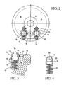
- the alignment pin 60 shown in Figure 3 has a frustoconical camming surface 74, the surface terminating upwardly in a generally flat top section 84.
- the camming surface 74 is pyramidal, the camming surface actually consisting of three or four or more upwardly convergent separate faces 86.
- the alignment pin 60 has an internal bore 88 which receives the spring 62, the camming surface 74 also being frustoconical.
- Various other configurations for the alignment pins will be evident to those skilled in the art.
- FIG. 6 Operation of the multi-tool device of the invention is illustrated schematically in Figures 6-9.
- the ram and the upper surface 48 of the striker housing are correctly rotationally aligned, and it will be noted that the ram is centered precisely between the alignment pins 60.
- the ram 50 is shown rotationally misaligned with respect to the striker housing.
- the ram is displaced slightly to the right so that as the ram descends, its edges will not be precisely centered between the alignment pin 60 as in Figure 6. Rather, the edge 82 of the ram will encounter the camming surface 74 of the nearest alignment pin, as shown in Figure 8, causing that alignment pin to be cammed to the right in Figure 8, resulting in a counterclockwise (from above) rotation of the striker housing 42.
- the ram is rotationally locked to the upper surface 48 of the striker housing so that as the magazine is rotated, the striker housing will remain rotationally stationary.
- the bottom face 46 of the striker does not have to be precisely centered on the upper surface 38 of the punch.
- the width of the striker at its bottom is such that it cannot contact two punches at one time, the striker may be offset slightly from the punch and still accomplish an acceptable punching operation.
- a slight rotational misalignment of the striker housing with respect to the punch magazine due to the realignment of the ram and striker housing as described above, may be permitted without damage to the punch or work piece.
- Rotational movement of the striker housing with respect to the ram of up to about 5° in either direction may be permitted.
- the camming surface 74 of the alignment pins shown in Figures 3-9 is at about 30° to the vertical to enable the pins to readily be cammed to one side or the other, although this angle can be varied as desired. An angle of 45° to the vertical may provide good results.
- the hemispherical pin shape shown in Figure 1 provides a curved camming surface in which the angle of the surface with respect to the vertical varies in accordance with the distance from the center of the hemispherical surface. It will be understood that a certain amount of camming force - a force acting horizontally on the pins - will be required in order to cause rotation of the striker housing as the ram descends.
- the spring 62 is chosen so that it is sufficiently stiff as to hold the pins upright in the position shown in Figures 7 and 8 as camming occurs, but yet is sufficiently yielding to enable the pin to be depressed fully within its recess in the event that the top surface 84 of the pin is encountered by the ram, as shown in Figure 9.
- a striker housing is designated generally as 90, and includes an externally threaded adjustment plug 92 that is threaded into a central, internally threaded bore 94 formed in the housing 90.
- the plug 92 has a generally circular cap 96 of increased diameter, the cap providing a downwardly facing annular shoulder 98 and having an upper striking surface 100 to be struck by a ram.
- the length of the multi-tool can thus be changed by screwing the plug into or out of the bore 94.
- a spring-loaded plunger 102 extends through a side wall of the housing 90 and has an inner end 104 that protrudes into contact with any one of a plurality of circumferentially spaced teeth 106 formed on the circumferential surface of the plug 92, for the purpose of rotationally locking the plug to the housing when the multi-tool has been adjusted to a desired length.
- Alignment pins 60 of the type shown in Figure 5 may be received in recesses 108 formed in the striker housing, as shown in Figure 11.
- the alignment pins are prevented from escaping from the recesses by press-fitted bushings 112, as described above, but in the working length of the multi-tool, the upward movement of the pins is restrained only by cap shoulder 98.
- the alignment pins simultaneously move inwardly or outwardly of their recesses but always maintain the same height with respect to the cap, as shown in Figure 11.
- the camming surface 74 of the alignment pins extends downwardly at least approximately to the level of the striking surface 100 of the cap.
- the camming surfaces 74 of the pins even when in their uppermost position, extend downwardly to the surface 48 of the striker housing (the surface 100 of the adjustment plug 92, in Figures 10 and 11) that is encountered by the ram so that relative rotation of a pin against the ram will cause camming of the pin into its recess.
Landscapes
- Engineering & Computer Science (AREA)
- Mechanical Engineering (AREA)
- Mounting, Exchange, And Manufacturing Of Dies (AREA)
- Automatic Assembly (AREA)
- Perforating, Stamping-Out Or Severing By Means Other Than Cutting (AREA)
Abstract
Description
- This invention relates to a self-aligning multi-tool of the type employed in punch presses, according to the preamble of claim 1.
- Punch presses commonly have an actuating ram, an upper platform which holds a punching tool, and a lower platform that supports a die in vertical alignment with the punching tool. Turret-type punch presses utilize a rotatable upper platform that has a series of tool mounting stations arranged around its periphery for receiving different punching or marking tools. Rotation of the platform brings a selected punch into position above a work station and beneath the ram. A lower platform is provided with a corresponding series of dies, and is rotatable with the upper platform to enable the proper die to be aligned with a selected punch. Note also DE-A-4 444 858.
- Certain punch tools themselves can be "multi-tools." That is, a punching tool, instead of containing only a single punch, may contain a magazine bearing a series of vertically movable punches in circumferentially spaced bores. The magazine itself can be rotated, as by a worm gear or the like, about a central vertical axis so as to place the correct punch above a work piece in a work station. Multi-tool mechanisms of this type are used, for example, for punching selected numbers or letters into a work piece, as well as for punching holes through the thickness of a work piece. A lower magazine containing a plurality of corresponding dies also may be provided so that as the magazine containing the punches is rotated about its axis, the lower magazine is rotated as well to bring the appropriate die into vertical alignment with the selected punch.
- Carried above a multi-tool magazine is a multi-tool carrying a striker. As the multi-tool is struck downwardly by the ram of a punch press, the striker is forced downwardly into contact with a vertically aligned punch, causing that punch in turn to strike the work piece. The width of the striker at its bottom end is generally less than the distance between adjacent punches in the magazine, so that the striker cannot strike more than one punch at a time.
- The multi-tool commonly is prevented by its contact with the punch press ram from rotating as the magazine is rotated about its axis to bring a selected tool into vertical alignment with the striker. In a typical procedure, the punch press ram descends into a rotationally locking engagement with the multi-tool, following which the magazine is rotated to bring a selected punch into alignment with the striker, and then the multi-tool is depressed further by the ram to cause the striker to engage the aligned punch in a punching operation.
- The striker housing and tool ram have faces configured so that when they are brought together, the striker housing is rotationally locked to the punch press ram. The punch press ram, for example, may have a flat, generally rectangular shaped bottom surface that is received into a complementary slot or other configuration of the striker housing so that the striker housing is held rotationally stationary by the punch press ram.
- A problem arises with certain punch presses in that the precise angular position of the punch press ram cannot be assured each time the striker housing is positioned over a tool ram. Rotational misalignment between the punch press ram and the striker housing may only be on the order of a few degrees, but may yet be sufficient to prevent the striker housing and the punch press ram from rotationally locking together.
Rotational misalignment of the ram with the striker housing may prevent the punch press ram, as it descends into contact with the striker housing, from rotationally locking to the striker housing. The striker housing itself hence may undergo some rotation as the magazine is rotated, with the result that the striker is not aligned with the correct punching tool. The work piece accordingly may be ruined, and substantial damage may result to the striker housing. - It would be desirable to correct any misalignment of the striker housing and the punch press ram so as to enable them to rotationally lock together and prevent rotation of the striker housing as the tool magazine is rotated beneath it.
- The present invention provides a self-aligning multi-tool for use in a punch press with the features of claim 1.
- Preferred embodiments are defined in dependent claims 2 to 10. Claim 11 relates to a punch press having the self-aligning multi-tool of the invention.
- In a preferred embodiment springs are provided to urge the alignment pins upwardly, the recesses being configured to enable the pins to be substantially completely received in the recesses when the ram and striker housing are severely mis-aligned. The springs, which may be helical springs received in the recesses, are sufficiently stiff so that downward pressure of the ram against the camming surface of an alignment pin causes the striker housing to rotate, rather than to depress the pin into its recess, but preferably are sufficiently yielding as to enable a pin to be depressed within its recess if the housing is forcibly rotated by the magazine with respect to the ram to restrain damage to the ram or multi-tool.
-
- Figure 1 is a partially broken away view, and partial cross-section, showing a multi-tool of the invention;
- Figure 2 is a top view of the tool of Figure 1;
- Figure 3 is a broken away, cross-sectional view of a portion of the multi-tool device of Figure 1, showing a modified embodiment thereof;
- Figure 4 is a broken away view of a portion of the device of Figure 3, showing another embodiment thereof;
- Figure 5 is a view similar to that of Figure 4, but showing yet another embodiment thereof;
- Figure 6 is a broken away schematic view of a portion of the multi-tool of the invention, showing a particular positioning of parts thereof;
- Figure 7 is a view similar to that of Figure 6 but showing misalignment of parts;
- Figure 8 is another view similar to that of Figure 6, and illustrating realignment of misaligned parts;
- Figure 9 is a view similar to that of Figure 6 but showing a different positioning of parts;
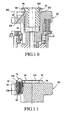
- Figure 10 is a broken-away view, in partial cross-section, of a modified multi-tool embodiment, with alignment pins removed; and
- Figure 11 is a cross sectional, broken-away view of the multi-tool of Figure 10 showing the position of an alignment pin.
-
- Exemplified in Figure 1 is a multi-tool according to a preferred embodiment of the invention, designated generally 10. The multi-tool includes a
tool magazine 12 having a generally cylindrically shape. The magazine includes a plurality ofvertical bores 14 about its periphery carrying, respectively, a plurality ofpunches 16, of which one is shown at 16. Thebottom tip 18 of the punch may have a cutting edge, as for forming holes in a workpiece, or may have one or more raised alphanumeric characters or some other symbol that is to be stamped into the workpiece. A stripper plate, shown at 20, is provided to enable the punch tip to be withdrawn from a work piece in the event that a cut is made through the thickness of the work piece. For completeness, a die is shown at 22, the die having a diesurface 24 capable of receiving thepunch tip 18. In the embodiment depicted, thepunch tip 18 is an alphanumeric character, and thedie surface 24 provides an upwardly facing flat surface to support the work piece immediately beneath the punch. - The magazine includes a
bottom plate 26 which carries thestripper plate 20 and which is mounted to thebody 28 through the use of aspring 30 carried about apost 32, the spring extending upwardly into arecess 34 about thepost 32 and being captured between theupper surface 36 of the recess and the upper surface of thebottom plate 26. - A striker housing designated generally as 40 includes an
housing body 42 that is rotationally mounted to themagazine 12 so that when thehousing body 42 is held stationary, the magazine may be rotated about its axis A with respect to the housing. Carried vertically in a bore formed in the housing is astriker 44, the striker having alower end 46 that is vertically aligned with thepunch 16. When the striker housing 42 of the multi-tool is held stationary, rotation of themagazine 12 bringspunching tools 16 sequentially into alignment beneath thestriker 44. The width of thetip 46 of the striker, measured circumferentially (that is, perpendicular to the plane of the paper in Figure 1) is less than the distance between theupper ends 48 of neighboring punches so that under no circumstances can the striker engage more than one punch at a time. On the other hand, theupper surface 38 of the punch is sufficient broad so that it can be struck by thestriker head 46 even though the striker and punch may be slightly rotationally mis-aligned, as will be explained in greater detail below. - Also shown in Figure 1 is the lower portion of a
punch press ram 50. The ram is typified in the drawing as having alower surface 52 that is generally rectangular in cross section, the long dimension of the ram being shown in Figure 1 and the shorter dimension of the ram being shown in, for example, Figures 6-9. The ram is driven mechanically, or, more commonly, hydraulically. The hydraulic or mechanical operation of punch presses is well known, and needs no further explanation. - The rotational orientation of a punch press ram is usually controlled with some precision, but occasionally the striking surface of the ram will vary from its intended rotational position so that it does not properly align rotationally with the upper
striking surface 48 of the striker housing. Inasmuch as close rotational alignment between the bottom of the ram and the top of the striking housing is required in order to lock the ram and housing rotationally together, slight rotational misalignment of the ram and striker housing may enable the striker housing to rotate with the magazine as the magazine is rotated, and it is to this problem that we now turn. It will be understood that the confronting, interlocking portions of the ram and the striker housing may have a variety of different configurations enabling them to lock together, and the particular configuration described below, in which the bottom, striking surface of the ram is generally rectangular in cross section, should be considered illustrative and not limiting. Typical ram face configurations include rectangular, key-hole, obround and double D shapes, the latter being essentially race track shaped. - With reference to Figures 1 and 2, a pair of spaced
recesses 54 are formed in the upper surface of the striker housing, the recesses preferably being bores that are upwardly open and that receive within them alignment pins 60, the upper ends of the alignment pins protruding above thesurface 48 of the striker housing. A spring, typified as ahelical spring 62, is positioned within each bore 54, the bottom of the spring pressing against the bottom of the bore and the upper end of the spring pressing upwardly against the bottom surface of thealignment pin 60 so as to urge the pin upwardly. - As shown in Figure 1, each
alignment pin 60 has an annular, upwardly facingshoulder 64. Thebore 54 itself may have an enlargedupper portion 56 within which is received abushing 66, the bushing having an annular, downwardly facingshoulder 68 that encounters theshoulder 64 so as to limit the upward movement afforded thepin 60. Thebushing 66 itself may have upwardly facing, opposedflat surfaces 70 ground into its external surface, as shown in Figure 1, and hold downscrews 72 may be employed to contact thesurfaces 70 of the bushing to retain the bushing in thebore 54. Thealignment pin 60 includes a tapered or roundedcamming surface 74 at an angle to the vertical. - Shown in phantom lines in Figure 2 is the "foot print" of the
ram 50 upon the upper surface of the striker housing, showing the proper orientation of the ram with respect to the alignment pins. It will be noted here that in this illustrative embodiment, the ram has a substantiallyrectangular portion 76 extending between thepin 60, and also a slightly enlargedcylindrical portion 78 that is coaxial with the axis A of the striker housing and of the magazine. - As shown best in Figure 7, the
side walls 80 of the ram meet thebottom striking surface 52 at slightly roundededges 82 to afford smooth sliding contact between theedges 82 of the ram and the slanted or tapered camming surfaces 74 of the alignment pins. - Different alignment pin configurations are shown in Figures 1, 3, 4 and 5. In Figure 1, the alignment pin has a generally hemispherical shape, and will be understood that as the
edge 82 of the descendingram 50 encounters an off-center portion of the hemispherical surface of an alignment pin, that alignment pin (and the body of the striker housing) will be cammed to one side. Referring to Figure 2, it should now be evident that such camming force actually urges the striker housing to rotate in one direction or the other around the axis A, depending upon the misalignment of the ram with the striker housing. - The
alignment pin 60 shown in Figure 3 has afrustoconical camming surface 74, the surface terminating upwardly in a generally flattop section 84. In Figure 4, thecamming surface 74 is pyramidal, the camming surface actually consisting of three or four or more upwardly convergent separate faces 86. In Figure 5, thealignment pin 60 has an internal bore 88 which receives thespring 62, thecamming surface 74 also being frustoconical. Various other configurations for the alignment pins will be evident to those skilled in the art. - Operation of the multi-tool device of the invention is illustrated schematically in Figures 6-9. In Figure 6, the ram and the
upper surface 48 of the striker housing are correctly rotationally aligned, and it will be noted that the ram is centered precisely between the alignment pins 60. - In Figure 7, the
ram 50 is shown rotationally misaligned with respect to the striker housing. The ram is displaced slightly to the right so that as the ram descends, its edges will not be precisely centered between thealignment pin 60 as in Figure 6. Rather, theedge 82 of the ram will encounter thecamming surface 74 of the nearest alignment pin, as shown in Figure 8, causing that alignment pin to be cammed to the right in Figure 8, resulting in a counterclockwise (from above) rotation of thestriker housing 42. Once the striker housing has been rotated so that the alignment shown in Figure 6 has been obtained, the ram is rotationally locked to theupper surface 48 of the striker housing so that as the magazine is rotated, the striker housing will remain rotationally stationary. - In extreme circumstances, the
punch press ram 50 may become so misaligned with the striker housing that correction of the alignment may no longer be feasible. This situation is illustrated in Figure 9. Here, anedge 82 of a descending ram has encountered instead the generally flatupper surface 84 of an alignment pin. To avoid substantial damage to the tool, thealignment pin 60 is simply depressed as the ram descends, the pin being received within its recess in the striker housing. - As mentioned above in connection with Figure 1, the
bottom face 46 of the striker does not have to be precisely centered on theupper surface 38 of the punch. Although the width of the striker at its bottom is such that it cannot contact two punches at one time, the striker may be offset slightly from the punch and still accomplish an acceptable punching operation. Hence, a slight rotational misalignment of the striker housing with respect to the punch magazine, due to the realignment of the ram and striker housing as described above, may be permitted without damage to the punch or work piece. Rotational movement of the striker housing with respect to the ram of up to about 5° in either direction may be permitted. - Preferably, the
camming surface 74 of the alignment pins shown in Figures 3-9 is at about 30° to the vertical to enable the pins to readily be cammed to one side or the other, although this angle can be varied as desired. An angle of 45° to the vertical may provide good results. The hemispherical pin shape shown in Figure 1 provides a curved camming surface in which the angle of the surface with respect to the vertical varies in accordance with the distance from the center of the hemispherical surface. It will be understood that a certain amount of camming force - a force acting horizontally on the pins - will be required in order to cause rotation of the striker housing as the ram descends. Thespring 62 is chosen so that it is sufficiently stiff as to hold the pins upright in the position shown in Figures 7 and 8 as camming occurs, but yet is sufficiently yielding to enable the pin to be depressed fully within its recess in the event that thetop surface 84 of the pin is encountered by the ram, as shown in Figure 9. - Referring now to the embodiment depicted in Figures 10 and 11, a striker housing is designated generally as 90, and includes an externally threaded adjustment plug 92 that is threaded into a central, internally threaded bore 94 formed in the
housing 90. At its upper end, theplug 92 has a generallycircular cap 96 of increased diameter, the cap providing a downwardly facingannular shoulder 98 and having an upperstriking surface 100 to be struck by a ram. The length of the multi-tool can thus be changed by screwing the plug into or out of thebore 94. A spring-loadedplunger 102 extends through a side wall of thehousing 90 and has aninner end 104 that protrudes into contact with any one of a plurality of circumferentially spacedteeth 106 formed on the circumferential surface of theplug 92, for the purpose of rotationally locking the plug to the housing when the multi-tool has been adjusted to a desired length. - Alignment pins 60 of the type shown in Figure 5 may be received in
recesses 108 formed in the striker housing, as shown in Figure 11. The pins, which are centered radially beyond the periphery of the cap, each have upwardly facingannular shoulders 110 which are urged upwardly into contact with theannular shoulder 98 of the cap bysprings 62. The alignment pins are prevented from escaping from the recesses by press-fittedbushings 112, as described above, but in the working length of the multi-tool, the upward movement of the pins is restrained only bycap shoulder 98. In this manner, as the adjustment plug is rotated with respect to the striker housing to change the distance that thecap 96 protrudes from thehousing recess 94, the alignment pins simultaneously move inwardly or outwardly of their recesses but always maintain the same height with respect to the cap, as shown in Figure 11. As with the earlier described embodiments, thecamming surface 74 of the alignment pins extends downwardly at least approximately to the level of thestriking surface 100 of the cap. - In the event that the striker housing and the magazine become unintentionally rotationally fixed to each other, as might happen, for example, if debris accumulates between them or a punch becomes stuck in its up position, then the striker housing will be forced to rotate with the magazine as the latter is rotated. The
ram 50, however, even though initially properly positioned between the alignment pins as in Figure 6, remains rotationally stationary. In this situation, thecamming surface 74 of one of the pins will encounter the ram edge as the striker housing is rotated, and thespring 62 accordingly must be sufficiently yielding so that horizontal rotation of the pin against the ram causes the pin to be cammed downwardly into its recess to avoid damage to the ram or to the multi-tool. It will be noted that the camming surfaces 74 of the pins, even when in their uppermost position, extend downwardly to thesurface 48 of the striker housing (thesurface 100 of theadjustment plug 92, in Figures 10 and 11) that is encountered by the ram so that relative rotation of a pin against the ram will cause camming of the pin into its recess. - While several forms of the invention have been shown and described, other forms will be apparent to those skilled in the art within the scope of the invention as defined by the appended claims. The embodiment shown on the drawings and described above are merely for illustrative purposes and are not intended to limit the scope of the invention, which is defined by the claims which follow.
Claims (11)
- A self-aligning multi-tool for use in a punch press having a ram (50), comprising a housing (40; 90) carrying a striker (44), a magazine (12) bearing a plurality of circumferentially spaced tools (16) and rotatable with respect to the housing (40; 90) so as to bring a single desired tool (16) into alignment with the striker (44), the housing (40; 90) having a striking surface (48) adapted to be engaged by the ram (50) of a punch press and rotationally aligned therewith to prevent the housing (40; 90) from rotating as the magazine (12) is rotated, characterised in that the housing (40; 90) includes a pair of alignment pins (60) carried adjacent the periphery of the housing (40; 90) each having a tapered cam surface (74) and positioned such that the ram (50) will contact and cam against the tapered cam surface (74) of the pins (60) as the ram (50) approaches the striking surface (48) if the ram (50) and the striking surface (48) are rotationally mis-aligned and each spaced so as to receive closely between them the ram (50) so as to urge the housing (40; 90) to rotate into correct alignment with the ram (50) to enable rotational locking therebetween.
- The multi-tool of claim 1, wherein the pins (60) have frustoconical camming surfaces (74).
- The multi-tool of claim 1, wherein the pins (60) have pyramidal camming surfaces.
- The multi-tool of claim 1, wherein the pins (60) have generally spheroidal camming surfaces.
- The multi-tool of any one of the preceding claims, wherein the housing (40) includes recesses (54) sized to substantially fully receive the alignment pins (60), and springs (62) urging the alignment pins (60) outwardly of the recesses (54).
- The multi-tool of claim 5, including an adjustment plug (92) threadably received in the striker housing (90) and having a cap defining the striking surface, the cap and alignment pins (60) having engaging portions restraining upward movement of the pins (60) and maintaining vertical alignment of the pins (60) with the cap striking surface.
- The multi-tool of any one of the preceding claims, in combination with a punch press having a ram (50) movable along an axis toward and away from the striking surface of the multi-tool, the ram (50) having a ram surface facing the striking surface of the striker housing (40; 90) and configured to rotationally lock to the housing (40; 90) between the pins (60) when correctly rotationally aligned with the housing (40; 90) to prevent the housing (40; 90) from rotating as the magazine (12) is rotated.
- The multi-tool of claim 7, wherein the ram surface includes an edge configured to contact and cam against the tapered cam surface (74) of a pin (60) as the ram (50) approaches the striking surface if the ram (50) and the striking surface are rotationally mis-aligned.
- The multi-tool of claim 7 or claim 8, wherein the tapered cam surfaces (74) are frustoconical.
- The multi-tool of claim 9, wherein the housing (40; 50) includes recesses (54) sized to substantially fully receive the alignment pins (60) and springs (62) urging each alignment pin (60) outwardly of its recess (54).
- A punch press having a ram (50), and a self-aligning multi-tool according to any one of claims 1 to 6.
Applications Claiming Priority (3)
| Application Number | Priority Date | Filing Date | Title |
|---|---|---|---|
| US431962 | 1999-11-01 | ||
| US09/431,962 US6279445B1 (en) | 1999-11-01 | 1999-11-01 | Multi-tool alignment apparatus |
| PCT/US2000/029988 WO2001032330A1 (en) | 1999-11-01 | 2000-10-31 | Multi-tool alignment apparatus |
Publications (2)
| Publication Number | Publication Date |
|---|---|
| EP1225988A1 EP1225988A1 (en) | 2002-07-31 |
| EP1225988B1 true EP1225988B1 (en) | 2004-12-22 |
Family
ID=23714186
Family Applications (1)
| Application Number | Title | Priority Date | Filing Date |
|---|---|---|---|
| EP00975517A Expired - Lifetime EP1225988B1 (en) | 1999-11-01 | 2000-10-31 | Multi-tool alignment apparatus |
Country Status (6)
| Country | Link |
|---|---|
| US (1) | US6279445B1 (en) |
| EP (1) | EP1225988B1 (en) |
| AU (1) | AU1356001A (en) |
| CA (1) | CA2389309C (en) |
| DE (1) | DE60016956T2 (en) |
| WO (1) | WO2001032330A1 (en) |
Cited By (1)
| Publication number | Priority date | Publication date | Assignee | Title |
|---|---|---|---|---|
| CN107708885A (en) * | 2015-10-07 | 2018-02-16 | 帕斯冲压技术股份公司 | Multi-purpose tool for hole punched device |
Families Citing this family (21)
| Publication number | Priority date | Publication date | Assignee | Title |
|---|---|---|---|---|
| FR2800312B1 (en) * | 1999-10-29 | 2002-01-25 | Automa Tech Sa | PUNCHING MACHINE FOR PANELS |
| AR027371A1 (en) | 2000-02-10 | 2003-03-26 | Envases Uk Ltd | DEFORMATION OF SLIM WALL BODIES |
| US7032812B2 (en) * | 2000-05-11 | 2006-04-25 | Euromac S.P.A. | Quick-extraction punch-holder adapter for converting punching machines from a single-punch to a multiple-punch configuration |
| US8287060B1 (en) | 2003-10-22 | 2012-10-16 | Metal Fabricating Corporation | Cabinet shelf with keyed slot |
| US7452039B1 (en) | 2004-08-10 | 2008-11-18 | Metal Fabricating Corporation | Cabinet shelf with keyed slot |
| US8042374B2 (en) * | 2006-04-07 | 2011-10-25 | Wilson Tool International Inc. | Multi-tool technology |
| US7726554B2 (en) * | 2006-10-19 | 2010-06-01 | Mate Precision Tooling Inc. | Multiple punch and die assembly providing hand disassembly, punch length adjustment and replacement |
| US8322545B1 (en) | 2006-12-21 | 2012-12-04 | Metal Fabricating Corporation | Curved bin for shelf |
| US7874194B2 (en) * | 2007-03-09 | 2011-01-25 | Wilson Tool International Inc. | Die holder technology for metal-fabricating press |
| WO2008153824A1 (en) * | 2007-05-30 | 2008-12-18 | Mate Precision Tooling, Inc. | Punch press die holder with hand-operated retaining clamp |
| US9211581B2 (en) * | 2007-09-21 | 2015-12-15 | Wilson Tool International Inc. | Stripper assemblies and components thereof for multi-tool punch assemblies |
| US7954404B2 (en) | 2008-04-29 | 2011-06-07 | Mate Precision Tooling, Inc. | Punch device with adjustment subassembly as retrofit insert or as original equipment |
| US20090320550A1 (en) * | 2008-06-27 | 2009-12-31 | Lee Brian J | Anti-Vibration Die Holder Technology for Fabricating Press |
| USD643656S1 (en) | 2009-06-09 | 2011-08-23 | Metal Fabricating Corporation | Front wall of a cabinet shelf |
| US8413561B2 (en) * | 2009-11-10 | 2013-04-09 | Mate Precision Tooling, Inc. | Multiple punch and die assembly |
| IT1400285B1 (en) | 2010-06-04 | 2013-05-24 | Euromac Spa | MULTI-TOOL UNIT FOR PUNCHING PRESSES |
| US9393711B2 (en) | 2011-04-11 | 2016-07-19 | Milwaukee Electric Tool Corporation | Hand-held knockout punch driver |
| CN203245254U (en) * | 2011-08-22 | 2013-10-23 | 密尔沃基电动工具公司 | Draw stud connector |
| JP5318167B2 (en) * | 2011-08-26 | 2013-10-16 | 株式会社日研工作所 | Rotary table device |
| DE102011087084A1 (en) * | 2011-11-25 | 2013-05-29 | Pass Stanztechnik Ag | Multi-tool |
| TWM603411U (en) * | 2020-05-18 | 2020-11-01 | 晏錦文 | Badge pressing machine |
Family Cites Families (20)
| Publication number | Priority date | Publication date | Assignee | Title |
|---|---|---|---|---|
| US1926985A (en) | 1929-09-05 | 1933-09-12 | Firm Ceskoslovenska Zbrojovka | Multistamping machine |
| US1940883A (en) | 1932-02-11 | 1933-12-26 | Rollings Ernest John | Turret punch |
| US2738864A (en) | 1951-08-18 | 1956-03-20 | Borg Warner | Clutch belleville spring type |
| US3921486A (en) | 1973-07-09 | 1975-11-25 | Manco Mfg Co | Machine tool for workpieces of extended dimension |
| FR2317058A1 (en) | 1975-07-09 | 1977-02-04 | Beauplat Fils Et Cie | PERFECTIONED TOOL HOLDER TURRET FOR PUNCHING MACHINE |
| US4165669A (en) | 1976-06-21 | 1979-08-28 | Strippit Division, Houdaille Industries, Inc. | Modular turret punch press |
| FR2409812A1 (en) | 1977-11-26 | 1979-06-22 | Behrens Ag C | CUTTING PRESS FOR WORKING PIECES IN THE FORM OF PLATES, IN PARTICULAR SHEET |
| US4285259A (en) | 1979-08-21 | 1981-08-25 | Houdaille Industries, Inc. | Turret index system |
| SE454654B (en) | 1986-09-24 | 1988-05-24 | Nordisk Kartro Ab | SET AND DEVICE FOR POSITIONING OF TOOLS RELATING TO A MATERIAL RANGE WITH REPEATED BASIC FORM |
| SE463082B (en) | 1986-10-24 | 1990-10-08 | Nordisk Kartro Ab | DEVICE FOR PROFILING A STEP FORMATED MATERIAL COVER |
| SE461195B (en) * | 1988-04-25 | 1990-01-22 | Pullmax Ab | TOOLS MOUNTED TO PUT TOOLS WITH SELECTABLE ACTIVABLE PUTS |
| US5201589A (en) | 1989-05-22 | 1993-04-13 | Murata Wiedemann | Marking tool holder for a punch press |
| US5072620A (en) | 1989-10-02 | 1991-12-17 | Strippit, Inc. | Stamping tool |
| US5048385A (en) | 1989-12-28 | 1991-09-17 | Strippit, Inc. | Indexable multi-tool for punch press |
| JP2580440B2 (en) * | 1992-07-21 | 1997-02-12 | 株式会社アマダメトレックス | Multiple dies for punch press |
| US5211095A (en) | 1992-08-20 | 1993-05-18 | Murata Machinery, Limited | Arrangement enabling variably oriented punching with each tool in a multiple tool holder |
| JP3170093B2 (en) * | 1993-04-01 | 2001-05-28 | 株式会社アマダ | Punching machine |
| US5382102A (en) | 1993-09-28 | 1995-01-17 | W. A. Whitney Co. | Indexable marking tool for use with a punch press |
| IT1264303B1 (en) * | 1993-12-24 | 1996-09-23 | Rainer Srl | PUNCHING MACHINE |
| IT1264302B1 (en) * | 1993-12-24 | 1996-09-23 | Rainer Srl | MACHINE FOR THE PROCESSING OF A SHEET METAL. |
-
1999
- 1999-11-01 US US09/431,962 patent/US6279445B1/en not_active Expired - Lifetime
-
2000
- 2000-10-31 WO PCT/US2000/029988 patent/WO2001032330A1/en not_active Ceased
- 2000-10-31 CA CA002389309A patent/CA2389309C/en not_active Expired - Lifetime
- 2000-10-31 EP EP00975517A patent/EP1225988B1/en not_active Expired - Lifetime
- 2000-10-31 DE DE60016956T patent/DE60016956T2/en not_active Expired - Lifetime
- 2000-10-31 AU AU13560/01A patent/AU1356001A/en not_active Abandoned
Cited By (2)
| Publication number | Priority date | Publication date | Assignee | Title |
|---|---|---|---|---|
| CN107708885A (en) * | 2015-10-07 | 2018-02-16 | 帕斯冲压技术股份公司 | Multi-purpose tool for hole punched device |
| CN107708885B (en) * | 2015-10-07 | 2019-10-22 | 帕斯冲压技术股份公司 | Multi-function tool for punching units |
Also Published As
| Publication number | Publication date |
|---|---|
| WO2001032330A1 (en) | 2001-05-10 |
| CA2389309C (en) | 2009-07-14 |
| DE60016956D1 (en) | 2005-01-27 |
| CA2389309A1 (en) | 2001-05-10 |
| US6279445B1 (en) | 2001-08-28 |
| DE60016956T2 (en) | 2005-12-29 |
| EP1225988A1 (en) | 2002-07-31 |
| AU1356001A (en) | 2001-05-14 |
Similar Documents
| Publication | Publication Date | Title |
|---|---|---|
| US6279445B1 (en) | Multi-tool alignment apparatus | |
| CA2780266C (en) | Multiple punch and die assembly | |
| EP1399279B1 (en) | Adjustable length punch assembly | |
| US3871254A (en) | Means for piercing and stripping thick material | |
| JP2747115B2 (en) | Adjustable punch set assembly | |
| US5072620A (en) | Stamping tool | |
| CA2180632C (en) | Workpiece-deforming tool and die for use in a punch press | |
| US5934165A (en) | Adjustable punch assembly | |
| US5848563A (en) | Multiple tool for punch press | |
| EP0399339B1 (en) | Marking tool holder for a punch press | |
| US5382102A (en) | Indexable marking tool for use with a punch press | |
| EP1084043A1 (en) | Marking device with marking punch resiliently biased towards its rest position | |
| JP2658499B2 (en) | Punch holder with stripper structure | |
| EP0267115B1 (en) | Piercing die | |
| US2655995A (en) | Means for registering noncylindrical punches and dies | |
| EP0560333A1 (en) | A punch press machine | |
| CN221388408U (en) | Shock absorber cover cut-out press with locate function | |
| JPS5925575Y2 (en) | drilling machine | |
| JPH0815629B2 (en) | Punch tool | |
| JPH07308714A (en) | Marking tool |
Legal Events
| Date | Code | Title | Description |
|---|---|---|---|
| PUAI | Public reference made under article 153(3) epc to a published international application that has entered the european phase |
Free format text: ORIGINAL CODE: 0009012 |
|
| 17P | Request for examination filed |
Effective date: 20020501 |
|
| AK | Designated contracting states |
Kind code of ref document: A1 Designated state(s): AT BE CH CY DE DK ES FI FR GB GR IE IT LI LU MC NL PT SE |
|
| AX | Request for extension of the european patent |
Free format text: AL;LT;LV;MK;RO;SI |
|
| 17Q | First examination report despatched |
Effective date: 20031113 |
|
| GRAP | Despatch of communication of intention to grant a patent |
Free format text: ORIGINAL CODE: EPIDOSNIGR1 |
|
| RBV | Designated contracting states (corrected) |
Designated state(s): DE FI FR GB IT |
|
| GRAA | (expected) grant |
Free format text: ORIGINAL CODE: 0009210 |
|
| GRAS | Grant fee paid |
Free format text: ORIGINAL CODE: EPIDOSNIGR3 |
|
| AK | Designated contracting states |
Kind code of ref document: B1 Designated state(s): DE FI FR GB IT |
|
| REG | Reference to a national code |
Ref country code: GB Ref legal event code: FG4D |
|
| REG | Reference to a national code |
Ref country code: IE Ref legal event code: FG4D |
|
| REF | Corresponds to: |
Ref document number: 60016956 Country of ref document: DE Date of ref document: 20050127 Kind code of ref document: P |
|
| PLBE | No opposition filed within time limit |
Free format text: ORIGINAL CODE: 0009261 |
|
| STAA | Information on the status of an ep patent application or granted ep patent |
Free format text: STATUS: NO OPPOSITION FILED WITHIN TIME LIMIT |
|
| ET | Fr: translation filed | ||
| 26N | No opposition filed |
Effective date: 20050923 |
|
| PGFP | Annual fee paid to national office [announced via postgrant information from national office to epo] |
Ref country code: FR Payment date: 20081014 Year of fee payment: 9 |
|
| PGFP | Annual fee paid to national office [announced via postgrant information from national office to epo] |
Ref country code: GB Payment date: 20081029 Year of fee payment: 9 |
|
| REG | Reference to a national code |
Ref country code: FR Ref legal event code: ST Effective date: 20100630 |
|
| PG25 | Lapsed in a contracting state [announced via postgrant information from national office to epo] |
Ref country code: FR Free format text: LAPSE BECAUSE OF NON-PAYMENT OF DUE FEES Effective date: 20091102 |
|
| PG25 | Lapsed in a contracting state [announced via postgrant information from national office to epo] |
Ref country code: GB Free format text: LAPSE BECAUSE OF NON-PAYMENT OF DUE FEES Effective date: 20091031 |
|
| PGFP | Annual fee paid to national office [announced via postgrant information from national office to epo] |
Ref country code: FI Payment date: 20191029 Year of fee payment: 20 Ref country code: DE Payment date: 20191029 Year of fee payment: 20 |
|
| PGFP | Annual fee paid to national office [announced via postgrant information from national office to epo] |
Ref country code: IT Payment date: 20191023 Year of fee payment: 20 |
|
| REG | Reference to a national code |
Ref country code: DE Ref legal event code: R071 Ref document number: 60016956 Country of ref document: DE |
|
| REG | Reference to a national code |
Ref country code: FI Ref legal event code: MAE |