EP1225845B1 - Method of installing a stent in a sleeve - Google Patents
Method of installing a stent in a sleeve Download PDFInfo
- Publication number
- EP1225845B1 EP1225845B1 EP00974024A EP00974024A EP1225845B1 EP 1225845 B1 EP1225845 B1 EP 1225845B1 EP 00974024 A EP00974024 A EP 00974024A EP 00974024 A EP00974024 A EP 00974024A EP 1225845 B1 EP1225845 B1 EP 1225845B1
- Authority
- EP
- European Patent Office
- Prior art keywords
- stent
- sleeve
- adaptor
- strands
- pulling
- Prior art date
- Legal status (The legal status is an assumption and is not a legal conclusion. Google has not performed a legal analysis and makes no representation as to the accuracy of the status listed.)
- Expired - Lifetime
Links
- 238000000034 method Methods 0.000 title claims description 33
- 238000010168 coupling process Methods 0.000 claims description 5
- 238000005859 coupling reaction Methods 0.000 claims description 5
- 230000008878 coupling Effects 0.000 claims description 4
- 238000013459 approach Methods 0.000 claims description 2
- 230000000452 restraining effect Effects 0.000 claims 1
- 239000011324 bead Substances 0.000 description 16
- 230000008569 process Effects 0.000 description 9
- QNRATNLHPGXHMA-XZHTYLCXSA-N (r)-(6-ethoxyquinolin-4-yl)-[(2s,4s,5r)-5-ethyl-1-azabicyclo[2.2.2]octan-2-yl]methanol;hydrochloride Chemical compound Cl.C([C@H]([C@H](C1)CC)C2)CN1[C@@H]2[C@H](O)C1=CC=NC2=CC=C(OCC)C=C21 QNRATNLHPGXHMA-XZHTYLCXSA-N 0.000 description 8
- 230000000694 effects Effects 0.000 description 6
- 229920000295 expanded polytetrafluoroethylene Polymers 0.000 description 6
- 238000009434 installation Methods 0.000 description 6
- 229910001000 nickel titanium Inorganic materials 0.000 description 6
- 238000007906 compression Methods 0.000 description 5
- 239000011159 matrix material Substances 0.000 description 5
- 230000006835 compression Effects 0.000 description 4
- 238000011900 installation process Methods 0.000 description 4
- 239000000463 material Substances 0.000 description 4
- HLXZNVUGXRDIFK-UHFFFAOYSA-N nickel titanium Chemical compound [Ti].[Ti].[Ti].[Ti].[Ti].[Ti].[Ti].[Ti].[Ti].[Ti].[Ti].[Ni].[Ni].[Ni].[Ni].[Ni].[Ni].[Ni].[Ni].[Ni].[Ni].[Ni].[Ni].[Ni].[Ni] HLXZNVUGXRDIFK-UHFFFAOYSA-N 0.000 description 4
- 238000013519 translation Methods 0.000 description 4
- 239000004642 Polyimide Substances 0.000 description 3
- 239000010432 diamond Substances 0.000 description 3
- 229910052751 metal Inorganic materials 0.000 description 3
- 239000002184 metal Substances 0.000 description 3
- 229920001721 polyimide Polymers 0.000 description 3
- XLYOFNOQVPJJNP-UHFFFAOYSA-N water Substances O XLYOFNOQVPJJNP-UHFFFAOYSA-N 0.000 description 3
- 238000003466 welding Methods 0.000 description 3
- 238000010276 construction Methods 0.000 description 2
- 238000013461 design Methods 0.000 description 2
- 230000005489 elastic deformation Effects 0.000 description 2
- 239000007943 implant Substances 0.000 description 2
- 230000006872 improvement Effects 0.000 description 2
- 230000003287 optical effect Effects 0.000 description 2
- 238000003908 quality control method Methods 0.000 description 2
- 229910001285 shape-memory alloy Inorganic materials 0.000 description 2
- 241000894006 Bacteria Species 0.000 description 1
- 241001264766 Callistemon Species 0.000 description 1
- HZEWFHLRYVTOIW-UHFFFAOYSA-N [Ti].[Ni] Chemical compound [Ti].[Ni] HZEWFHLRYVTOIW-UHFFFAOYSA-N 0.000 description 1
- 230000006978 adaptation Effects 0.000 description 1
- 229910045601 alloy Inorganic materials 0.000 description 1
- 239000000956 alloy Substances 0.000 description 1
- 238000002399 angioplasty Methods 0.000 description 1
- 210000004204 blood vessel Anatomy 0.000 description 1
- 230000000295 complement effect Effects 0.000 description 1
- 238000001816 cooling Methods 0.000 description 1
- 238000005520 cutting process Methods 0.000 description 1
- 238000005538 encapsulation Methods 0.000 description 1
- 230000006698 induction Effects 0.000 description 1
- 230000001939 inductive effect Effects 0.000 description 1
- 230000036512 infertility Effects 0.000 description 1
- 208000014674 injury Diseases 0.000 description 1
- 239000007788 liquid Substances 0.000 description 1
- 230000014759 maintenance of location Effects 0.000 description 1
- 238000004519 manufacturing process Methods 0.000 description 1
- 230000004048 modification Effects 0.000 description 1
- 238000012986 modification Methods 0.000 description 1
- 239000002245 particle Substances 0.000 description 1
- 230000000149 penetrating effect Effects 0.000 description 1
- 239000004033 plastic Substances 0.000 description 1
- 238000005498 polishing Methods 0.000 description 1
- 229920001343 polytetrafluoroethylene Polymers 0.000 description 1
- 239000004810 polytetrafluoroethylene Substances 0.000 description 1
- 239000002510 pyrogen Substances 0.000 description 1
- 238000011084 recovery Methods 0.000 description 1
- 230000004044 response Effects 0.000 description 1
- 239000000758 substrate Substances 0.000 description 1
- 238000001356 surgical procedure Methods 0.000 description 1
- 210000003813 thumb Anatomy 0.000 description 1
- 230000036962 time dependent Effects 0.000 description 1
- 230000007704 transition Effects 0.000 description 1
- 230000008733 trauma Effects 0.000 description 1
- 210000005166 vasculature Anatomy 0.000 description 1
- 230000000007 visual effect Effects 0.000 description 1
Images




Classifications
-
- A—HUMAN NECESSITIES
- A61—MEDICAL OR VETERINARY SCIENCE; HYGIENE
- A61F—FILTERS IMPLANTABLE INTO BLOOD VESSELS; PROSTHESES; DEVICES PROVIDING PATENCY TO, OR PREVENTING COLLAPSING OF, TUBULAR STRUCTURES OF THE BODY, e.g. STENTS; ORTHOPAEDIC, NURSING OR CONTRACEPTIVE DEVICES; FOMENTATION; TREATMENT OR PROTECTION OF EYES OR EARS; BANDAGES, DRESSINGS OR ABSORBENT PADS; FIRST-AID KITS
- A61F2/00—Filters implantable into blood vessels; Prostheses, i.e. artificial substitutes or replacements for parts of the body; Appliances for connecting them with the body; Devices providing patency to, or preventing collapsing of, tubular structures of the body, e.g. stents
- A61F2/95—Instruments specially adapted for placement or removal of stents or stent-grafts
- A61F2/9522—Means for mounting a stent or stent-graft onto or into a placement instrument
- A61F2/9525—Means for mounting a stent or stent-graft onto or into a placement instrument using a funnel
-
- A—HUMAN NECESSITIES
- A61—MEDICAL OR VETERINARY SCIENCE; HYGIENE
- A61F—FILTERS IMPLANTABLE INTO BLOOD VESSELS; PROSTHESES; DEVICES PROVIDING PATENCY TO, OR PREVENTING COLLAPSING OF, TUBULAR STRUCTURES OF THE BODY, e.g. STENTS; ORTHOPAEDIC, NURSING OR CONTRACEPTIVE DEVICES; FOMENTATION; TREATMENT OR PROTECTION OF EYES OR EARS; BANDAGES, DRESSINGS OR ABSORBENT PADS; FIRST-AID KITS
- A61F2/00—Filters implantable into blood vessels; Prostheses, i.e. artificial substitutes or replacements for parts of the body; Appliances for connecting them with the body; Devices providing patency to, or preventing collapsing of, tubular structures of the body, e.g. stents
- A61F2/95—Instruments specially adapted for placement or removal of stents or stent-grafts
-
- A—HUMAN NECESSITIES
- A61—MEDICAL OR VETERINARY SCIENCE; HYGIENE
- A61F—FILTERS IMPLANTABLE INTO BLOOD VESSELS; PROSTHESES; DEVICES PROVIDING PATENCY TO, OR PREVENTING COLLAPSING OF, TUBULAR STRUCTURES OF THE BODY, e.g. STENTS; ORTHOPAEDIC, NURSING OR CONTRACEPTIVE DEVICES; FOMENTATION; TREATMENT OR PROTECTION OF EYES OR EARS; BANDAGES, DRESSINGS OR ABSORBENT PADS; FIRST-AID KITS
- A61F2/00—Filters implantable into blood vessels; Prostheses, i.e. artificial substitutes or replacements for parts of the body; Appliances for connecting them with the body; Devices providing patency to, or preventing collapsing of, tubular structures of the body, e.g. stents
- A61F2/95—Instruments specially adapted for placement or removal of stents or stent-grafts
- A61F2/9522—Means for mounting a stent or stent-graft onto or into a placement instrument
-
- A—HUMAN NECESSITIES
- A61—MEDICAL OR VETERINARY SCIENCE; HYGIENE
- A61F—FILTERS IMPLANTABLE INTO BLOOD VESSELS; PROSTHESES; DEVICES PROVIDING PATENCY TO, OR PREVENTING COLLAPSING OF, TUBULAR STRUCTURES OF THE BODY, e.g. STENTS; ORTHOPAEDIC, NURSING OR CONTRACEPTIVE DEVICES; FOMENTATION; TREATMENT OR PROTECTION OF EYES OR EARS; BANDAGES, DRESSINGS OR ABSORBENT PADS; FIRST-AID KITS
- A61F2/00—Filters implantable into blood vessels; Prostheses, i.e. artificial substitutes or replacements for parts of the body; Appliances for connecting them with the body; Devices providing patency to, or preventing collapsing of, tubular structures of the body, e.g. stents
- A61F2/95—Instruments specially adapted for placement or removal of stents or stent-grafts
- A61F2002/9505—Instruments specially adapted for placement or removal of stents or stent-grafts having retaining means other than an outer sleeve, e.g. male-female connector between stent and instrument
- A61F2002/9511—Instruments specially adapted for placement or removal of stents or stent-grafts having retaining means other than an outer sleeve, e.g. male-female connector between stent and instrument the retaining means being filaments or wires
Definitions
- This invention relates to methods for installing a self-expanding stent into a confining sleeve at the distal end of a stent delivery system.
- stents that may be placed within a human vessel are those characterized as "self-expanding" stents which are confinable, in a small diameter, in the distal end of a catheter-like delivery device in readiness for advancement to and release within a selected site in the vessel.
- stents may be made of a shaped memory alloy, such as a nickel-titanium alloy.
- such stents may be made from a cylinder of the alloy with a diameter corresponding to, but usually somewhat less than, the diameter which the stent has in its compressed delivery configuration, that is, when it is confined within a sheath of a stent delivery system, for introduction into the body of the patient, for placement at the desired site within the body.
- the confining sheath is withdrawn proximally, allowing the compressed stent to expand, from memory, to an expanded configuration in which it supports the wall of the bodily lumen in which it is sited.
- the starting cylinder may be laser-cut to create a matrix of through openings, and then expanded to expanded diameter. It is then heated to give it a "memory" of this configuration. After that, it is necessary to compress the stent sufficient to introduce it into the sleeve or sheath of the delivery system.
- the compression and loading of the stent into the sleeve may be performed manually and may involve using a fixture, such as a conical funnel through which the stent is urged to progressively compress it to a smaller diameter in which it can be installed into the sleeve.
- the stent may be covered by an appropriate graft material, such as expanded polytetrafluoroethylene (ePTFE), defining a stent-graft.
- ePTFE expanded polytetrafluoroethylene
- the graft may be a bare, uncovered stent.
- the compression and loading of the stent into the sleeve involves a number of manual steps, there is significant risk of variation in the manner in which the stent engages and is seated within the sleeve.
- One object of the present invention is to provide a stent compression process which will allow the step of installing the stent in its delivery sheath or sleeve to be conducted in a more automated way, which should facilitate the objectives of strict quality control, predictability, and further process improvement. Also among the objects of the invention are to provide a process for controlling the degree of longitudinal force applied to the stent; to accurately and repeatedly position the stent at a predetermined distance from the distal end of the delivery sheath; to support the stent from within during its compression.
- C. R. Bard, Inc. proposes to install a stent graft in a sleeve by a process which involves pushing a leading end of the stent graft into a conical confining funnel, until the leading end of the stent, at the tip of the funnel, at its compressed configuration, engages with radially extending spokes of an implant retention device within the sleeve of the delivery system.
- the spokes act within the sleeve as an anchor, to prevent undesirable axial movements of the stent graft within the sheath/sleeve, or in deployment of the stent graft from the sheath.
- the implant expands on deployment, it moves radially outwardly away from the spokes of the anchor device, thereby automatically releasing the anchor device for withdrawal from the blood vessel.
- Bourne et al discloses use of conical-shaped lumen for collapsing a prosthetic occluder into a narrow or slender configuration advanceable through the lumen of an introducer sheath.
- the system is described as a front-end loader and contrasted with the Rashkind prior art rear-end loading delivery system.
- the prosthesis is held on a locking wire, but is drawn by a plurality of suture lines down the conical confinement surface, in a direction opposite to that in which the wire extends away from the prosthesis.
- WO 97/17021 Dereume discloses a device to recover into a lumen a stent previously placed in a bodily lumen.
- the device deploys a ring of hooks to engage one end of the stent and pull it down a flared end of a lumen of the elongate recovery device. See also WO 2000/02615 and CA 2213291 (Gianotti).
- the manual stent installation process for a nickel-titanium stent also may involve cooling the stent to below room temperature, in a water bath. While this is acceptable for an uncoated metal stent, which can be subsequently sterilized totally, it is less attractive for a coated stent or a stent graft, because of the potential for the prosthesis to carry bacteria and pyrogens, originating in the water bath.
- the elongate puller is provided as a wire, and that wire is mounted to a post which serves as the puller holder.
- the post is fixedly mounted to the base, which extends under the device and provides a substrate for a carriage, which carries the gripper, gripper holder and constrictor.
- a servo-motor in the carriage serves as the translator, to move the carriage along the base away from the post, thereby to translate the sleeve past the stent, as the stent is held on the wire.
- a force sensor is interposed between the wire and the post, in order to monitor the tensile force in the wire.
- This force sensor inputs a data processor which is itself controlling the servo-motor, so that translation can be stopped if the tensile force in the wire rises too high.
- one or more sensors can be located adjacent the sleeve, at the far end, to monitor the arrival of the stent at the far end, and ensure that the stent is brought to the desired end there.
- Characteristic of the invention is the adaptor which is able to engage an end of the stent when the stent is expanded, and also adapted to be released from the stent, when the stent is compressed.
- a circle of hooks is provided, each of these hooks being on a long stem running hack to the elongate puller.
- Each of the hooks can be provided with a bight which has a radially outward-facing opening, so that the circle of hooks can be introduced inside the rim of the leading end of the stent, following which, the outward opening bight of each hook is passed through respective apertures in the cylindrical envelope of the stent, so that the point of each hook lies outside the cylindrical envelope of the stent.
- the circle of hooks is arranged at evenly-spaced intervals around the circumference of the leading end of the stent.
- the hooks can be provided as a ball on the end of each stem. With the stem in tension, and the ball radially outside the cylindrical stent envelope, the rhombus vertex catches the ball and prevents the ball passing radially inwardly through the stent envelope, until the tension on the wire is released.
- the adaptor has to be detached from the leading end of the stent.
- the structure of the adaptor has enough column strength to allow it to be pushed towards the stent, so that the circle of hooks is itself urged towards the trailing end of the stent, thereby freeing the bight of each hook from the respective vertex of the leading end rhombus with which it is engaged.
- a collar surrounding the circle of stems of the hooks can be urged towards the trailing end of the stent.
- the stems With the diameter of the collar sufficiently small, the stems are urged radially inwardly, themselves bringing the circle of hooks to a circular envelope with a diameter smaller than the inside diameter of the compressed stent wall.
- the collar has a leading end rim which passes into the open bight of each of the hooks, and fills the bight, thereby denying any other structure the possibility of falling into the bight of each hook, as the circle of hooks is withdrawn past the leading end of the stent.
- each stem could end in a loop instead of a hook, and a purse string could be threaded through apertures of the stent as well as each of said loops. Release of such an adaptor is effected by pulling out the purse string.
- the stems need not be resilient and no surrounding collar is required.
- a plurality of pull strings or wires are used each being threaded through two apices of a stent matrix at the leading end of the stent, these two apices being at opposite ends of a diameter across the stent lumen.
- Two, three, four or more of such strings can be arranged across different diameters.
- a single retraction string can be looped around all the pull strings, and can lead out through the stent past the opposite, trailing end of the stent, to pull out the pull strings when their work is done.
- each pull string could have its own release string.
- Each pull string could pass through only one stent apex, or more than two apices.
- an adaptor of another form entirely could be used.
- a structure along the axis of the device has a plurality of push strands which are arranged around the circumference of the axis and are resistant to longitudinal compressive stress.
- One end of each strand is fixed to the axial structure and the other is cantilevered radially outside it. With the fixed ends closer to the trailing end of the stent, pulling on the axial structure from in front of the leading end of the stent brings the cantilevered ends of the strands into contact with push surfaces of the stent, such as apices of its mesh.
- the push strands could be arranged as the ribs of an umbrella with its apex remote from the leading end of the stent and its ribs engaging the stent near its leading end.
- An adapter alternately may have the general form of a chuck, which grips the leading end of the stent between two co-axial annular members, which move axially towards each other to grip the stent and away from each other to release the stent.
- the location of the stent relative to the base remains constant, and the translator moves the sleeve relative to the base, until the stent is in the desired location within the sleeve.
- the sleeve does not move relative to the base, but the stent is translated, relative to the base as well as the sleeve.
- the invention is particularly well suited to the installation of stents which are otherwise not well adapted to installation under water in a sleeve. Thus, it is well adapted to installing encapsulated or covered stents, but can also be used to install bare stents.
- the invention is particularly attractive in respect of stents which are themselves sleeved or encapsulated. With the stent being pulled from its leading end, there is friction acting between the stent and the surfaces which are compressing it, leading to a tensile stress within the length of the stent. Some stents are not well adapted to withstand such longitudinal tensile stresses, but sleeved or encapsulated stents are often better able to resist such tensile stresses, because the encapsulation or sleeve can share the longitudinal tensile stresses imposed on the stent.
- the stent is one which carries a sleeve of expanded PTFE (ePTFE), which is fixed to the metallic cylinder of the stent at zones corresponding to the leading and trailing ends of the stent, but not over the middle part of the length of the stent.
- ePTFE expanded PTFE
- One way of achieving this result is to place bands of ePTFE inside the cylindrical envelope of the stent, one at each end of the stent, on a mandrel which then receives the stent and the abluminal ePTFE sleeve.
- the assembly is sintered, causing the sleeve and bands to bond together, through the apertures of the stent cylinder, at each end of the stent.
- the ePTFE sleeve is relatively inextensible, and therefore supports the metal stent cylinder against elastic and plastic deformation which might otherwise occur under the tensile stresses imposed on the stent as it is drawn into the sleeve.
- the sleeve As to the loading of the stent into a sleeve, the sleeve is itself elastically deformable, and, in one loading technique, will be subject to tensile stresses during the stent installation process. These forces will produce tensile strain in the sleeve. Unless allowance is made for this strain in the installation operation, then the actual position of the stent in the sleeve will not correspond to the desired position. To compensate for the effect of strain in the sleeve, the speed of translation is reduced as the stent approaches the desired end point of its travel within the sleeve.
- a laser beam extending across the path of the sleeve can serve to detect the presence or absence of the sleeve, thereby detecting whether the sleeve is still strained and, in effect, establishing whether the actual position of the far end surface of the sleeve corresponds to the desired location.
- a magnetic inductance sensor detects the arrival of the stent being translated with the sleeve at the desired location near the distal end of the sleeve. Data from these two sensors, delivered to the data processor, allow the data processor to terminate the pulling process at a point which places the stent at a desired distance from the far end surface of the sleeve.
- FIG. 1 there is shown a stent 10 in its expanded configuration, and with a leading end 12 and a trailing end 14, an abluminal surface 16 and a luminal surface 18.
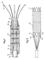
- a circle of hooks 20 engages the leading end 12 of the stent.
- Each of the hooks 20 has a long stem 22, and all of these stems extend to a root portion 24 located close to a long axis 26 of the device in general.
- a collar 28 Over the circle of root portions 24 of the stems 22 is a collar 28 which is slidable over the stems 22, up to the hooks 20.
- detent surfaces other than hooks could be used.
- a little ball of the end of each stem 22 might be effective, depending on the design of the locations in the stent where the stems are to be coupled.
- An elongate puller in the form of a wire 30 is attached to the portions 24 of the stems 22 and extends through and beyond the collar 28.
- the structure of hooks 20, stems 22, and collar 28 constitute an adaptor 41 which couples the trailing end 43 of the pulling wire 30 to the leading end of the stent 10.
- the sleeve 32 into which the stent is to be loaded is supported to receive the pulling wire 30 that extends through the lumen 33 of the sleeve.
- a receiving end 50 of the sleeve 32 is gripped in a gripper chuck 34.
- the chuck 34 is in fixed position or relationship to a constrictor 36 which is in the form of a block 38 of large thermal capacity, which itself defines a tapered, conveniently conical, constricting surface 40 with a wide end 42 and a narrow end 44.
- a shoulder surface 46 at the end of a bore surface 48 which snugly receives the receiving end 50 of the sleeve 32.
- the sleeve has a long axis corresponding to the axis 26 of the device in general. As will be described, the stent will be compressed and drawn into and through the sleeve 32 until the stent is located in a predetermined position at the opposite end of the sleeve.
- the receiving end 50 of the sleeve thus will serve as the proximal end of the delivery device and the opposite end of the sleeve will serve as the distal end to be inserted into the patient.
- the stent When the stent is positioned in the sleeve in readiness for deployment in the patient, it will be located near the distal end of the sleeve.
- a mandrel 52 which has a tapered conical surface 54 which complements the tapered conical surface 40 of the constrictor block 38, so that advancement of the mandrel 52 along the axis 26, into the conical cavity of the constrictor block 38 leads to the definition of a conical annular space through which the hook stems 22 extend.
- the constrictor could oscillate axially to assist advance of the stent down to its narrow end. If so, it may be helpful to provide the taper surfaces with a "one-way" structure of steps and terraces, like the underside of a cross-country ski, so that the constrictor can slip backwards relatively easily but on its forward stroke towards the leading end of the stent, tends to carry the stent with it.
- the cone could be coated with a slippery material to assist stent advance.
- a carriage which carries the gripper chuck 34 and constrictor 36 and mandrel 52 is caused to move to the right as shown in Figure 1, while the pulling wire 30 is held fast.
- this has the effect of drawing the hooks 20 down the annular space adjacent the tapered conical surface 40 of the block 38, and the hooks carry with them the leading end 12 of the stent 10.
- the full length of the stent 10 is drawn down the cone and into the receiving end 50 of the sleeve 32. Further progress of the carriage to the right in Figure 1 pulls the stent 10 along the full length of the sleeve 32.
- a welding bead of fillet 64 fixes the root zones 24 of the stems 22 to the pulling wire 30.
- the stems 22 are surrounded by a moving collar 62.
- the fixed sleeve 60 is attached by a welding bead 64 to the pulling wire 30.
- the outside diameter of the collar ring 68 is somewhat smaller than the outside diameter of the moving collar 62.
- Inside the moving collar 62 is a plurality of apertured rings 72.
- each of the rings 72 has a circle of 12 apertures, each to receive a different one of the stems 22.
- These apertured rings '72 serve to maintain the spaced even circular arrangement of the long stems 22 and help the stems resist buckling in response to a compressive load.
- the moving collar 62 is brought to a proximal location as shown in Figure 2.
- the stems 22 are provided with a relaxed disposition in which they curve radially outwardly, so that the hooks 20 are on a circular envelope of relatively large diameter. Sliding the collar 62 to the right hand side in Figure 2 brings the rim 70 of the collar ring 68 into the bight 74 of each of the hooks 20.
- the stems 72 deform elastically, and the circle on which the hooks 20 is located is now a circle of radius corresponding to the radius of the collar ring 68.
- FIG. 3 shows the circle of hooks 20 each engaged with a different rhombic aperture 80 at the leading end of the stent 10.
- each rhombic aperture has a vertex 82 closest to, the leading end 12 of the stent 10 and it is with this vertex 82 that each hook 20 is engaged, for pulling the stent 10 into the sleeve 32.
- the collar 62 is slid tip to the hooks 20 and then the circle of hooks 20 is introduced into the leading end of the stent, to bring each of the hooks 20 into a position more or less central within its corresponding rhombic aperture 80. Then the collar 62 is slid proximally back towards the Figure 2 position, allowing the hooks 20 to expand radially outwardly by resilient elastic deformation of the stems 22, until each hook 20 penetrates through the cylindrical envelope of the stent 10 at one of the rhombic apertures 80, with each of the twelve hooks, 20 extending through a different one of the circle of twelve rhombic apertures 80 at the leading end of the stent 10.
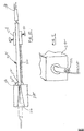
- the sleeve 32 destined to receive the stent 10 is gripped in chuck 34 and the wire 30 is, then passed through the constrictor block 38 and sleeve 32, until its leading end 39 can be made fast to a puller holder, ready for pulling the stent 10 into the sleeve 32.
- a carriage 100 mounted for linear translational movement towards and away from the post 90.
- a servo motor 102 controlled, via lead 104, by the data processor 98.
- the carriage 100 carries the constrictor 36, mandrel 52 and sleeve gripper 34.
- the sleeve 32 is supported from below on a beam 106 which extends from the carriage 100 the full length of the sleeve 32, up to a peninsular block 108 supported above the base 92 by an undercarriage 110.
- the peninsular block 108 travels with the carriage 100, when the servo motor 102 is actuated.
- a plurality of sensor elements mounted on the peninsular block 108, which supports the far end of the sleeve 32, is a plurality of sensor elements, in particular, an optical sensor 112 and a magnetic induction sensor 114.
- the inductive sensor 114 detects the arrival, at the distal 37 of the sleeve 32, of the stent 10, and to signal that arrival to the data processor 98, through lead 118.
- the optical sensor 112 passes a laser beam across the locus of the sleeve 32 to sense the end of the sleeve and inform the data processor through lead 116, so that the stent 10 can be brought to a precisely specified location in the sleeve 32 relative to the sleeve end.
- the sleeve 32 is fixed against movement relative to the peninsular block 108, but only at its receiving (proximal) end 50, so that tensile stresses in the sleeve 32 can alter the position of its distal 37 relative to the sensor 112. Provision of sensor 112 therefore can inform the data processor when the tensile strain in the sleeve 32 has fallen below a specified low value, corresponding to arrival of the stent at the desired end position, and enabling the pulling process to be terminated to lace the stent at just the correct desired distance from the distal end of the sleeve. Readers will appreciate that elastic deformation of the synthetic polymeric materials of stent sleeves is a time-dependent phenomenon, so time has to be allowed, at the end of the pulling process, for the sleeve to relax into its unstressed length.
- Figure 4 shows the device before stent installation begins
- Figure 5 shows the device once stent installation is complete.
- the stent installation process proceeds as follows.
- the carriage 100 With the pulling wire coupled to the stent, and installed as described above with reference to Figure 1, the carriage 100 is moved to the right in Figure 4, so as to bring the leading end 12 of the stent 10 to the wide end 42 of the conical constricting surface 40.
- the mandrel 52 is advanced to the left in Figure 4, along a key way 120 until it fits within the block 38 to complement the block conical surface 40.
- Further translation of the carriage 100, in the direction of arrow F has the effect of carrying the constrictor block 36 along the length of the stent 10, from the leading end 12 towards the trailing end 14, so that the length of the stent is drawn down the conical surface 40 and into the receiving end 50 of the sleeve 32.
- the data processor 98 arrests movement of the carriage by terminating the drive power to the servo motor 102.
- substantially the full length of the sleeve 32 is under tensile stress, leading to an increase in its length.
- the information which the data processor receives from sensors 112, 114 allows it to translate the sleeve 32 to a position relative to the stent 10 which sets the stent 10 at exactly the desired distance from the end surface of the sleeve 32.
- further translation of the carriage 100 is stopped, and the installation process is complete.
- the device can be switched off, and the sleeve 32 removed from it, with the stent 10 in place, yet still connected by the adaptor hook ring to the pulling wire 30.
- the stent and sleeve stand alone, and can be passed forward for the further steps of the process of constructing the stent delivery system.
- the distal end of the sleeve is not engaged mechanically by any component of the loading system.
- the end can therefore be polished in an earlier process step, and does not need to be cut or polished after loading. This is important, because the steps of cutting and polishing could conceivably give rise to the undesirable presence of loose particles inside the sleeve at its distal end.
- the other end of the sleeve, which has been held in the gripper chuck 34, is the proximal end of the sleeve in use. This can be cut, if necessary, after the stent has been loaded.
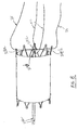
- Figure. 6 shows a leading end portion of another embodiment of stent 112.
- the material of the stent matrix is continued into an extending portion 174 with a width comparable to its thickness dimension so that, in cross-section, it is more or less square.
- a spherical Nitinol bead 176 which has a through bore on a diameter of the bead, to receive the spigot 174.
- the Nitinol bead 176 is welded to the spigot 174.
- the free vertices defining the end of the stent, and the end of each cell in the end ring of cells of the stent is less likely to cause trauma in the bodily tissue in which the end vertices is embedded, than if the spheres 176 were absent.
- the ring of beads 176 brings advantages when it comes to loading the stent onto a delivery system, and keeping control of the stent while the stent is being deployed into the body from the delivery system. Specifically, the ring of relatively thick beads 176 provides a point of purchase for gripping surfaces to impose forces on the stent, while it is being loaded into a delivery system, and while it is being deployed from that delivery system.
- the beads 176 could be gripped between circumferential surfaces, one inside the stent annulus and one outside the stent annulus, with a spacing between such co-axial surfaces which is wide enough to receive the thickness of the stent matrix, but does grip the spheres 176 on each side of the thickness of the stent matrix.
- the stent 112 is shown schematically within the truncated cone of a loading mandrel 190, with its 1eading end at the narrow end of the cone, tipped by the beads 176.
- a loading rod 192 with a somewhat larger diameter head 194, the transition from the head 194 to the cylindrical portion 196 of the rod 192 being accomplished by an arcuate shoulder surface 198.
- the concave outer surface of the shoulder 198 has a curvature which corresponds to the curvature of the beads 176.
- a gripping sleeve 200 which has at its gripping end 202 an arcuate gripping shoulder 204, also having a curvature corresponding to that of the spherical surface of the bead 176.
- the block 206 receives a sleeve 208 in which the stent 112 is to be housed, in a delivery system for placing the stent 112 at a desired location within the body, for location, a catheter.
- a delivery system for placing the stent 112 at a desired location within the body, for location, a catheter.
- the gripping sleeve 200 can be withdrawn forwardly, i.e. downwardly in the Figure 7 view, while the gripper rod 192 can be withdrawn rearwardly from the stent, i.e. upwardly as shown in Figure 7 and back past the trailing end of the stent.
- Figures 8-11 illustrate, diagrammatically, another technique and apparatus for compressing the stent and loading it into the distal end of the sleeve of the delivery device.
- one or more wires such as slender, superelastic nitinol wires, may be attached to the rhombi or diamonds, at the proximal end of the stent.
- Figure 8 shows two such wires 310, 312. The wire 310 is passed through a pair of diametrically opposite diamonds 308a, 308b and another wire 312 may be passed through another pair of diametrically opposite diamonds 308c, 308d.
- the free tails of the wires 310, 312 may be wrapped together, as with tape, and threaded through a funnel-like constrictor 314.
- the constrictor has an enlarged inlet end 316 and a narrowed outlet end 318 that opens into a fitting 320 adapted to engage the distal end 322 of the sleeve 324 into which the stent is to be loaded.
- the tails of the wires 310, 312 are passed through the sleeve 324 and exit out of the proximal end 326 of the sleeve.
- the device includes a clamp 328 that is separable to receive the sleeve 324.
- the clamp may be of a two-part construction having thumb screws 330 to enable the clamp parts to be secured together to clamp the sleeve 324.
- the clamp 328 is in a fixed position with respect to the constrictor 314, as by securing them to a common frame (not shown).
- the device also includes a trough-like support 332 that extends between the clamp 328 and the fitting 320 to support the portion of the sleeve 324 that extends between those components.
- the stent can be drawn through the constrictor 314 and into the lumen of the sleeve 324 simply by pulling on the tails of the wires 310, 312.
- the sleeve 324 may be transparent or translucent sufficiently to enable the stent to be visually observed as it advances into the distal end of the sleeve 324. Under such visual observation, the stent may be drawn into the distal end of the sleeve 324 to the precise location desired. The pull wires 310, 312 then may be withdrawn by pulling on one of the tails of each of the wires.
- an additional retraction wire 334 can be employed to enable withdrawal of the pull wires out of the distal end of the sleeve 324.
- a retraction wire 334 constructed similarly to the pull wires 310, 312 is inserted through the distal end of the stent, out through the proximal end, and is looped about the crossed region P of the pull wires 310, 312, the end of the retraction wire 334 being passed back out through the distal end of the stent.
- the pull wires 310, 312 are withdrawn by pulling on the retraction wire in a distal direction.
- the retraction wire 334 being looped about the crossed pull wires, draws the pull wires, at their bight, through the sleeve 324, the stent, and the constrictor 314.
- a polyimide support tube 336 can be inserted into the distal end of the stent as the stent is advanced into the constrictor.
- the polyimide tube is sufficiently stiff to provide luminal support for the stent as the stent is constricted and compressed to its smaller diameter.
- the polyimide tube 336 although providing internal support for the stent, nevertheless enables the retraction wire 334 as well as the pull wires 310, 312 to slide between the inner lumen of the stent and the support tube 336 to permit their removal.
- the invention contributes to the art of stents by providing improvements in methods of loading a stent into a sleeve of a delivery system in a way which can be controlled by a data processor.
- Such automation furthers the objectives of consistency and quality control.
- Data for particular designs of stent and sleeve can be stored in the data processor, with the corresponding parameters, especially the limiting load on the pulling system, in order that the data processor shall stop pulling when the limit load is exceeded.
- the data processor will drive the system in accordance with a constant program using the stored data.
- the system described above has been found to be able to handle consistently and reliably stents of a relatively large diameter too large for manual loading. Sleeving the stent in a gaseous environment furthers the object of sterility.
- the invention allows ready adaptation, to enable sleeving at any desired non-ambient temperature.
Landscapes
- Health & Medical Sciences (AREA)
- Engineering & Computer Science (AREA)
- Biomedical Technology (AREA)
- Cardiology (AREA)
- Oral & Maxillofacial Surgery (AREA)
- Transplantation (AREA)
- Heart & Thoracic Surgery (AREA)
- Vascular Medicine (AREA)
- Life Sciences & Earth Sciences (AREA)
- Animal Behavior & Ethology (AREA)
- General Health & Medical Sciences (AREA)
- Public Health (AREA)
- Veterinary Medicine (AREA)
- Media Introduction/Drainage Providing Device (AREA)
Abstract
Description
Claims (14)
- A method of installing a stent in a sleeve, comprising the steps ofi) coupling the stent, in an expanded configuration of the stent, to an adaptorii) drawing the adaptor lengthwise within the sleeve, to pull the stent into the sleeve, andiii) de-coupling the adaptor from the stent once the stent is inside
and characterized by the steps ofiv) coupling the distal end of the stent to the adaptorv) pulling the stent into the proximal end of the sleeve, and the through the full length of the sleeve till the distal end of the stent is at the distal end of the sleeve; andvi) incorporating the sleeve and stent in a stent delivery system with the stent at the distal end of the delivery system where it is releasable by a proximal withdrawal of the sleeve relative to the stent. - Method according to claim 1, including the step of coupling the adaptor to the stent at a plurality of push points spaced around the circumference of the leading end of the stent.
- Method according to claim 2, including the step of providing the adaptor as a plurality of strands, each to engage with different ones of the push points.
- Method according to claim 3, wherein each of the strands is a pull string, and each of the pull strings is associated with the push points in one-to-one correspondence.
- Method according to claim 3, wherein each of the strands is a pull string which is looped around a pair of push points, the members of the pair being diametrically apart on the leading end of the stent.
- Method according to claim 3, 4 or 5, including the step of pulling the strands off the stent from a point beyond the trailing end of the stent, to de-couple the adaptor from the stent once the stent is inside the sleeve.
- Method according to claim 6, including the step of threading a release string around each of the adaptor strands, whereby pulling on the release string pulls all the strands off the leading end of the stent.
- Method according to any one of claims 1 to 5, including the step of pushing the strands off the stent from a point beyond the leading end of the stent.
- Method according to any one of claims 1 to 8, including the step of sensing a load imposed on the stent when drawing the stent into the sleeve, and arresting the drawing movement when a pre-set limit load is reached.
- Method according to any one of claims 1 to 9, including the step of defining an end position of the stent relative to the sleeve, sensing the approach of the stent to said end position, and arresting the drawing movement when the end position is sensed.
- Method according to any one of claims 1 to 10, including the step of maintaining the stent at a temperature other than ambient temperature; during the drawing step.
- Method according to any one of claims 1 to 11, including the step of pulling the stent down a funnel into the sleeve.
- Method according to claim 12, including the step of oscillating the funnel along its long axis, to facilitate progress of the stent towards the narrow end of the funnel.
- Method according to any one of claims 1 to 13, including the step of restraining the sleeve at a stent-receiving end thereof, so that friction forces between the stent and the sleeve, as the stent is introduced into the sleeve, impose on the sleeve an axial tensile stress.
Applications Claiming Priority (3)
| Application Number | Priority Date | Filing Date | Title |
|---|---|---|---|
| GBGB9925636.4A GB9925636D0 (en) | 1999-10-29 | 1999-10-29 | Method of, and device for, installing a stent in a sleeve |
| GB9925636 | 1999-10-29 | ||
| PCT/US2000/029904 WO2001035861A1 (en) | 1999-10-29 | 2000-10-30 | Method of, and device for, installing a stent in a sleeve |
Publications (2)
| Publication Number | Publication Date |
|---|---|
| EP1225845A1 EP1225845A1 (en) | 2002-07-31 |
| EP1225845B1 true EP1225845B1 (en) | 2005-08-31 |
Family
ID=10863617
Family Applications (1)
| Application Number | Title | Priority Date | Filing Date |
|---|---|---|---|
| EP00974024A Expired - Lifetime EP1225845B1 (en) | 1999-10-29 | 2000-10-30 | Method of installing a stent in a sleeve |
Country Status (6)
| Country | Link |
|---|---|
| EP (1) | EP1225845B1 (en) |
| JP (1) | JP2003530143A (en) |
| DE (1) | DE60022373T2 (en) |
| ES (1) | ES2248141T3 (en) |
| GB (1) | GB9925636D0 (en) |
| WO (1) | WO2001035861A1 (en) |
Cited By (1)
| Publication number | Priority date | Publication date | Assignee | Title |
|---|---|---|---|---|
| EP4114326A4 (en) * | 2020-03-05 | 2024-03-27 | Fluid Biomed Inc. | SYSTEM AND METHOD FOR COMPRESSING ENDOVASCULAR DEVICES |
Families Citing this family (70)
| Publication number | Priority date | Publication date | Assignee | Title |
|---|---|---|---|---|
| DE10212707A1 (en) * | 2002-03-21 | 2003-10-02 | Phytis Medical Devices Gmbh | Device for compressing implants |
| US7766973B2 (en) | 2005-01-19 | 2010-08-03 | Gi Dynamics, Inc. | Eversion resistant sleeves |
| US7678068B2 (en) | 2002-12-02 | 2010-03-16 | Gi Dynamics, Inc. | Atraumatic delivery devices |
| AU2003298801B9 (en) | 2002-12-02 | 2008-07-31 | Gi Dynamics, Inc. | Bariatric sleeve |
| US7695446B2 (en) | 2002-12-02 | 2010-04-13 | Gi Dynamics, Inc. | Methods of treatment using a bariatric sleeve |
| US7025791B2 (en) | 2002-12-02 | 2006-04-11 | Gi Dynamics, Inc. | Bariatric sleeve |
| US7608114B2 (en) | 2002-12-02 | 2009-10-27 | Gi Dynamics, Inc. | Bariatric sleeve |
| DE10341092B4 (en) | 2003-09-05 | 2005-12-22 | Siemens Ag | Installation for non-contact movement and / or fixation of a magnetic body in a working space using a magnetic coil system |
| DE10340925B3 (en) | 2003-09-05 | 2005-06-30 | Siemens Ag | Magnetic coil system for non-contact movement of a magnetic body in a working space |
| US7815589B2 (en) | 2003-12-09 | 2010-10-19 | Gi Dynamics, Inc. | Methods and apparatus for anchoring within the gastrointestinal tract |
| US8057420B2 (en) | 2003-12-09 | 2011-11-15 | Gi Dynamics, Inc. | Gastrointestinal implant with drawstring |
| DE10359981A1 (en) | 2003-12-19 | 2005-07-21 | Siemens Ag | System and method for in vivo positioning and orientation determination of an endoscopy capsule or an endo-robot in the context of a wireless endoscopy |
| EP2308425B2 (en) | 2004-03-11 | 2023-10-18 | Percutaneous Cardiovascular Solutions Pty Limited | Percutaneous Heart Valve Prosthesis |
| JP4856067B2 (en) | 2004-07-09 | 2012-01-18 | ジーアイ・ダイナミックス・インコーポレーテッド | Method and apparatus for positioning a gastrointestinal sleeve |
| EP1799145B1 (en) | 2004-09-17 | 2016-12-21 | GI Dynamics, Inc. | Gastrointestinal anchor |
| US7771382B2 (en) | 2005-01-19 | 2010-08-10 | Gi Dynamics, Inc. | Resistive anti-obesity devices |
| WO2006086709A1 (en) * | 2005-02-11 | 2006-08-17 | Cook Incorporated | Method of loading expandable medical device in a low vapor environment |
| US7976488B2 (en) | 2005-06-08 | 2011-07-12 | Gi Dynamics, Inc. | Gastrointestinal anchor compliance |
| WO2007058857A2 (en) | 2005-11-10 | 2007-05-24 | Arshad Quadri | Balloon-expandable, self-expanding, vascular prosthesis connecting stent |
| US8753384B2 (en) * | 2006-05-19 | 2014-06-17 | Boston Scientific Scimed, Inc. | Apparatus and method for loading and delivering a stent |
| FR2902642B1 (en) * | 2006-06-21 | 2009-02-27 | D Arleux Eric Morel | ENDOPROSTHESIS OF THE "STENT" TYPE |
| FR2902641B1 (en) * | 2006-06-22 | 2008-09-26 | Tokendo Soc Par Actions Simpli | DEVICE FOR LOADING PROSTHESES |
| US7819836B2 (en) | 2006-06-23 | 2010-10-26 | Gi Dynamics, Inc. | Resistive anti-obesity devices |
| US20110257723A1 (en) | 2006-11-07 | 2011-10-20 | Dc Devices, Inc. | Devices and methods for coronary sinus pressure relief |
| CA2664557C (en) | 2006-11-07 | 2015-05-26 | Corvia Medical, Inc. | Devices and methods for the treatment of heart failure |
| US9232997B2 (en) | 2006-11-07 | 2016-01-12 | Corvia Medical, Inc. | Devices and methods for retrievable intra-atrial implants |
| US10413284B2 (en) | 2006-11-07 | 2019-09-17 | Corvia Medical, Inc. | Atrial pressure regulation with control, sensing, monitoring and therapy delivery |
| US8801647B2 (en) | 2007-02-22 | 2014-08-12 | Gi Dynamics, Inc. | Use of a gastrointestinal sleeve to treat bariatric surgery fistulas and leaks |
| CA2749026C (en) | 2008-09-29 | 2018-01-09 | Impala, Inc. | Heart valve |
| CA2739275C (en) | 2008-10-01 | 2017-01-17 | Impala, Inc. | Delivery system for vascular implant |
| EP2358298A1 (en) * | 2008-12-17 | 2011-08-24 | Abbott Laboratories Vascular Enterprises Limited | System and method for crimping body lumen filters |
| AU2010236288A1 (en) | 2009-04-15 | 2011-10-20 | Cardiaq Valve Technologies, Inc. | Vascular implant and delivery system |
| EP2470122B1 (en) * | 2009-08-28 | 2019-10-09 | Medtronic 3F Therapeutics, Inc. | Crimping device and method of use |
| US9757107B2 (en) | 2009-09-04 | 2017-09-12 | Corvia Medical, Inc. | Methods and devices for intra-atrial shunts having adjustable sizes |
| US9730790B2 (en) | 2009-09-29 | 2017-08-15 | Edwards Lifesciences Cardiaq Llc | Replacement valve and method |
| WO2011093941A2 (en) * | 2010-01-29 | 2011-08-04 | Dc Devices, Inc. | Devices and systems for treating heart failure |
| WO2011094521A2 (en) | 2010-01-29 | 2011-08-04 | Dc Devices, Inc. | Devices and methods for reducing venous pressure |
| US8579964B2 (en) | 2010-05-05 | 2013-11-12 | Neovasc Inc. | Transcatheter mitral valve prosthesis |
| US8752261B2 (en) * | 2010-07-07 | 2014-06-17 | Abbott Cardiovascular Systems Inc. | Mounting stents on stent delivery systems |
| EP3459500B1 (en) | 2010-09-23 | 2020-09-16 | Edwards Lifesciences CardiAQ LLC | Replacement heart valves and delivery devices |
| US12303119B2 (en) | 2011-02-10 | 2025-05-20 | Corvia Medical, Inc. | Apparatus and methods to create and maintain an intra-atrial pressure relief opening |
| JP2014512869A (en) | 2011-02-10 | 2014-05-29 | ディーシー ディヴァイシーズ インコーポレイテッド | Apparatus and method for forming and maintaining an intraatrial pressure relief opening |
| US9554897B2 (en) | 2011-04-28 | 2017-01-31 | Neovasc Tiara Inc. | Methods and apparatus for engaging a valve prosthesis with tissue |
| US9308087B2 (en) | 2011-04-28 | 2016-04-12 | Neovasc Tiara Inc. | Sequentially deployed transcatheter mitral valve prosthesis |
| EP2520251A1 (en) | 2011-05-05 | 2012-11-07 | Symetis SA | Method and Apparatus for Compressing Stent-Valves |
| US9205236B2 (en) | 2011-12-22 | 2015-12-08 | Corvia Medical, Inc. | Methods, systems, and devices for resizable intra-atrial shunts |
| EP2628469A3 (en) * | 2012-02-16 | 2017-07-05 | Biotronik AG | Crimping device and method for mounting a vascular stent |
| US9345573B2 (en) | 2012-05-30 | 2016-05-24 | Neovasc Tiara Inc. | Methods and apparatus for loading a prosthesis onto a delivery system |
| US9724219B2 (en) | 2012-10-04 | 2017-08-08 | Abbott Cardiovascular Systems Inc. | Method of uniform crimping and expansion of medical devices |
| US9199348B2 (en) | 2012-11-27 | 2015-12-01 | Medtronic, Inc. | Prosthetic valve crimping |
| US10583002B2 (en) | 2013-03-11 | 2020-03-10 | Neovasc Tiara Inc. | Prosthetic valve with anti-pivoting mechanism |
| US9681951B2 (en) | 2013-03-14 | 2017-06-20 | Edwards Lifesciences Cardiaq Llc | Prosthesis with outer skirt and anchors |
| US9730791B2 (en) | 2013-03-14 | 2017-08-15 | Edwards Lifesciences Cardiaq Llc | Prosthesis for atraumatically grasping intralumenal tissue and methods of delivery |
| US9572665B2 (en) | 2013-04-04 | 2017-02-21 | Neovasc Tiara Inc. | Methods and apparatus for delivering a prosthetic valve to a beating heart |
| WO2015013666A1 (en) | 2013-07-26 | 2015-01-29 | Cardiaq Valve Technologies, Inc. | Systems and methods for sealing openings in an anatomical wall |
| USD755384S1 (en) | 2014-03-05 | 2016-05-03 | Edwards Lifesciences Cardiaq Llc | Stent |
| US10675450B2 (en) | 2014-03-12 | 2020-06-09 | Corvia Medical, Inc. | Devices and methods for treating heart failure |
| US10667931B2 (en) | 2014-07-20 | 2020-06-02 | Restore Medical Ltd. | Pulmonary artery implant apparatus and methods of use thereof |
| JP6799526B2 (en) | 2014-07-23 | 2020-12-16 | コルヴィア メディカル インコーポレイテッド | Equipment and methods for the treatment of heart failure |
| CN113384384A (en) * | 2015-06-29 | 2021-09-14 | 莱拉医药公司 | Stent loading and delivery system |
| US10350062B2 (en) | 2016-07-21 | 2019-07-16 | Edwards Lifesciences Corporation | Replacement heart valve prosthesis |
| US11771434B2 (en) | 2016-09-28 | 2023-10-03 | Restore Medical Ltd. | Artery medical apparatus and methods of use thereof |
| US10660773B2 (en) | 2017-02-14 | 2020-05-26 | Abbott Cardiovascular Systems Inc. | Crimping methods for thin-walled scaffolds |
| CN110691554B (en) | 2017-06-05 | 2022-11-01 | 恢复医疗有限公司 | Double-walled fixed-length stent-like device and method of use |
| US10555825B2 (en) | 2017-11-09 | 2020-02-11 | Abbott Cardiovascular Systems Inc. | Rotation of a medical device during crimping |
| US10967556B2 (en) | 2018-06-11 | 2021-04-06 | Abbott Cardiovascular Systems Inc. | Uniform expansion of thin-walled scaffolds |
| US11607322B2 (en) | 2019-02-01 | 2023-03-21 | Suremka, Llc | Graft compression system |
| CN114404104B (en) * | 2020-10-28 | 2025-08-12 | 先健科技(深圳)有限公司 | Tectorial membrane support assembly quality |
| CN115429508B (en) * | 2022-09-16 | 2025-05-02 | 江苏博朗森思医疗器械有限公司 | Stent Loader |
| CN117281653B (en) * | 2023-10-30 | 2025-12-16 | 安徽肺畅医疗科技有限公司 | Intrabronchial valve loader |
Family Cites Families (11)
| Publication number | Priority date | Publication date | Assignee | Title |
|---|---|---|---|---|
| JP2961287B2 (en) | 1991-10-18 | 1999-10-12 | グンゼ株式会社 | Biological duct dilator, method for producing the same, and stent |
| US5626599A (en) | 1992-01-22 | 1997-05-06 | C. R. Bard | Method for the percutaneous transluminal front-end loading delivery of a prosthetic occluder |
| US5843167A (en) * | 1993-04-22 | 1998-12-01 | C. R. Bard, Inc. | Method and apparatus for recapture of hooked endoprosthesis |
| EP0657147B1 (en) | 1993-11-04 | 1999-08-04 | C.R. Bard, Inc. | Non-migrating vascular prosthesis |
| BE1009746A3 (en) | 1995-11-07 | 1997-07-01 | Dereume Jean Pierre Georges Em | Capture device introduced in a cavity of a human or animal body. |
| US5749921A (en) | 1996-02-20 | 1998-05-12 | Medtronic, Inc. | Apparatus and methods for compression of endoluminal prostheses |
| EP0829242A1 (en) | 1996-08-19 | 1998-03-18 | Schneider (Europe) Ag | Removal device for an implanted endoprothesis |
| US6352561B1 (en) * | 1996-12-23 | 2002-03-05 | W. L. Gore & Associates | Implant deployment apparatus |
| US6132458A (en) * | 1998-05-15 | 2000-10-17 | American Medical Systems, Inc. | Method and device for loading a stent |
| WO1999062428A1 (en) * | 1998-06-04 | 1999-12-09 | Scimed Life Systems, Inc. | Stent loading tool |
| WO2000002615A1 (en) | 1998-07-10 | 2000-01-20 | Shin Ishimaru | Stent (or stent graft) indwelling device |
-
1999
- 1999-10-29 GB GBGB9925636.4A patent/GB9925636D0/en not_active Ceased
-
2000
- 2000-10-30 JP JP2001537657A patent/JP2003530143A/en active Pending
- 2000-10-30 WO PCT/US2000/029904 patent/WO2001035861A1/en not_active Ceased
- 2000-10-30 EP EP00974024A patent/EP1225845B1/en not_active Expired - Lifetime
- 2000-10-30 ES ES00974024T patent/ES2248141T3/en not_active Expired - Lifetime
- 2000-10-30 DE DE60022373T patent/DE60022373T2/en not_active Expired - Lifetime
Cited By (1)
| Publication number | Priority date | Publication date | Assignee | Title |
|---|---|---|---|---|
| EP4114326A4 (en) * | 2020-03-05 | 2024-03-27 | Fluid Biomed Inc. | SYSTEM AND METHOD FOR COMPRESSING ENDOVASCULAR DEVICES |
Also Published As
| Publication number | Publication date |
|---|---|
| WO2001035861A1 (en) | 2001-05-25 |
| EP1225845A1 (en) | 2002-07-31 |
| JP2003530143A (en) | 2003-10-14 |
| DE60022373D1 (en) | 2005-10-06 |
| DE60022373T2 (en) | 2006-06-29 |
| ES2248141T3 (en) | 2006-03-16 |
| GB9925636D0 (en) | 1999-12-29 |
| WO2001035861A8 (en) | 2008-01-10 |
Similar Documents
| Publication | Publication Date | Title |
|---|---|---|
| EP1225845A1 (en) | Method of, and device for, installing a stent in a sleeve | |
| US8177832B2 (en) | Endoluminal expansion system | |
| AU2016201671B2 (en) | Medical device assembly with constriction mechanism | |
| CA2734680C (en) | Method of loading a stent into a sheath | |
| US7926320B2 (en) | Apparatuses for crimping and loading of intraluminal medical devices | |
| US6210434B1 (en) | Multicapsule intraluminal grafting system and method | |
| EP1515668B1 (en) | Implantable prosthesis | |
| US9687370B2 (en) | Method of loading a stent into a sheath | |
| US6939369B2 (en) | Intraluminal graft assembly and vessel repair system | |
| US20140336745A1 (en) | Stent graft with fixing elements and insertion system | |
| JPH0576554A (en) | Blood vessel-implanting apparatus, system and method, and apparatus used together therewith | |
| CA2485622A1 (en) | Self-expanding stent and stent delivery system for treatment of vascular disease | |
| WO2009085786A1 (en) | Prosthesis loading delivery and deployment apparatus | |
| EP4452099B1 (en) | An intravascular device with an improved attachment of its elements and a method of manufacturing thereof | |
| CN108135619A (en) | Medical Device Delivery Systems | |
| US20250134539A1 (en) | An intravascular device with an improved attachment of its elements and a method of manufacturing thereof | |
| EP4509099A2 (en) | Branched endoprosthesis with tail for controlled branch deployment |
Legal Events
| Date | Code | Title | Description |
|---|---|---|---|
| PUAI | Public reference made under article 153(3) epc to a published international application that has entered the european phase |
Free format text: ORIGINAL CODE: 0009012 |
|
| 17P | Request for examination filed |
Effective date: 20020521 |
|
| AK | Designated contracting states |
Kind code of ref document: A1 Designated state(s): AT BE CH CY DE DK ES FI FR GB GR IE IT LI LU MC NL PT SE |
|
| RIN1 | Information on inventor provided before grant (corrected) |
Inventor name: HEINZ, UWE Inventor name: DEBB, DEBRA, A. Inventor name: CUNDY, SANDRA, M. Inventor name: HOFFMANN, MARTINA Inventor name: LOMBARDI, SYLVIE Inventor name: EDELMANN, ANDREAS Inventor name: VOGEL, MICHAEL |
|
| 17Q | First examination report despatched |
Effective date: 20031218 |
|
| RBV | Designated contracting states (corrected) |
Designated state(s): AT BE CH CY DE ES FR GB IT LI |
|
| GRAP | Despatch of communication of intention to grant a patent |
Free format text: ORIGINAL CODE: EPIDOSNIGR1 |
|
| RTI1 | Title (correction) |
Free format text: METHOD OF INSTALLING A STENT IN A SLEEVE |
|
| RBV | Designated contracting states (corrected) |
Designated state(s): DE ES FR GB IT |
|
| GRAS | Grant fee paid |
Free format text: ORIGINAL CODE: EPIDOSNIGR3 |
|
| GRAA | (expected) grant |
Free format text: ORIGINAL CODE: 0009210 |
|
| AK | Designated contracting states |
Kind code of ref document: B1 Designated state(s): DE ES FR GB IT |
|
| REG | Reference to a national code |
Ref country code: GB Ref legal event code: FG4D |
|
| REF | Corresponds to: |
Ref document number: 60022373 Country of ref document: DE Date of ref document: 20051006 Kind code of ref document: P |
|
| REG | Reference to a national code |
Ref country code: ES Ref legal event code: FG2A Ref document number: 2248141 Country of ref document: ES Kind code of ref document: T3 |
|
| ET | Fr: translation filed | ||
| PLBE | No opposition filed within time limit |
Free format text: ORIGINAL CODE: 0009261 |
|
| STAA | Information on the status of an ep patent application or granted ep patent |
Free format text: STATUS: NO OPPOSITION FILED WITHIN TIME LIMIT |
|
| 26N | No opposition filed |
Effective date: 20060601 |
|
| PGFP | Annual fee paid to national office [announced via postgrant information from national office to epo] |
Ref country code: ES Payment date: 20071120 Year of fee payment: 8 |
|
| PGFP | Annual fee paid to national office [announced via postgrant information from national office to epo] |
Ref country code: IT Payment date: 20071029 Year of fee payment: 8 |
|
| PGFP | Annual fee paid to national office [announced via postgrant information from national office to epo] |
Ref country code: FR Payment date: 20071009 Year of fee payment: 8 |
|
| REG | Reference to a national code |
Ref country code: FR Ref legal event code: ST Effective date: 20090630 |
|
| PG25 | Lapsed in a contracting state [announced via postgrant information from national office to epo] |
Ref country code: IT Free format text: LAPSE BECAUSE OF NON-PAYMENT OF DUE FEES Effective date: 20081030 |
|
| PG25 | Lapsed in a contracting state [announced via postgrant information from national office to epo] |
Ref country code: FR Free format text: LAPSE BECAUSE OF NON-PAYMENT OF DUE FEES Effective date: 20081031 |
|
| REG | Reference to a national code |
Ref country code: ES Ref legal event code: FD2A Effective date: 20081031 |
|
| PG25 | Lapsed in a contracting state [announced via postgrant information from national office to epo] |
Ref country code: ES Free format text: LAPSE BECAUSE OF NON-PAYMENT OF DUE FEES Effective date: 20081031 |
|
| PGFP | Annual fee paid to national office [announced via postgrant information from national office to epo] |
Ref country code: DE Payment date: 20101027 Year of fee payment: 11 |
|
| PGFP | Annual fee paid to national office [announced via postgrant information from national office to epo] |
Ref country code: GB Payment date: 20101027 Year of fee payment: 11 |
|
| GBPC | Gb: european patent ceased through non-payment of renewal fee |
Effective date: 20121030 |
|
| PG25 | Lapsed in a contracting state [announced via postgrant information from national office to epo] |
Ref country code: DE Free format text: LAPSE BECAUSE OF NON-PAYMENT OF DUE FEES Effective date: 20130501 Ref country code: GB Free format text: LAPSE BECAUSE OF NON-PAYMENT OF DUE FEES Effective date: 20121030 |
|
| REG | Reference to a national code |
Ref country code: DE Ref legal event code: R119 Ref document number: 60022373 Country of ref document: DE Effective date: 20130501 |