EP1225751A2 - Portable telephone - Google Patents
Portable telephone Download PDFInfo
- Publication number
- EP1225751A2 EP1225751A2 EP02250174A EP02250174A EP1225751A2 EP 1225751 A2 EP1225751 A2 EP 1225751A2 EP 02250174 A EP02250174 A EP 02250174A EP 02250174 A EP02250174 A EP 02250174A EP 1225751 A2 EP1225751 A2 EP 1225751A2
- Authority
- EP
- European Patent Office
- Prior art keywords
- power source
- portable telephone
- telephone
- charging
- user
- Prior art date
- Legal status (The legal status is an assumption and is not a legal conclusion. Google has not performed a legal analysis and makes no representation as to the accuracy of the status listed.)
- Granted
Links
Images


Classifications
-
- H—ELECTRICITY
- H04—ELECTRIC COMMUNICATION TECHNIQUE
- H04B—TRANSMISSION
- H04B1/00—Details of transmission systems, not covered by a single one of groups H04B3/00 - H04B13/00; Details of transmission systems not characterised by the medium used for transmission
- H04B1/38—Transceivers, i.e. devices in which transmitter and receiver form a structural unit and in which at least one part is used for functions of transmitting and receiving
- H04B1/3827—Portable transceivers
- H04B1/385—Transceivers carried on the body, e.g. in helmets
-
- H—ELECTRICITY
- H04—ELECTRIC COMMUNICATION TECHNIQUE
- H04B—TRANSMISSION
- H04B1/00—Details of transmission systems, not covered by a single one of groups H04B3/00 - H04B13/00; Details of transmission systems not characterised by the medium used for transmission
- H04B1/06—Receivers
- H04B1/08—Constructional details, e.g. cabinet
- H04B1/086—Portable receivers
- H04B1/088—Portable receivers with parts of the receiver detachable or collapsible
-
- H—ELECTRICITY
- H04—ELECTRIC COMMUNICATION TECHNIQUE
- H04B—TRANSMISSION
- H04B1/00—Details of transmission systems, not covered by a single one of groups H04B3/00 - H04B13/00; Details of transmission systems not characterised by the medium used for transmission
- H04B1/38—Transceivers, i.e. devices in which transmitter and receiver form a structural unit and in which at least one part is used for functions of transmitting and receiving
- H04B1/3827—Portable transceivers
- H04B1/3883—Arrangements for mounting batteries or battery chargers
Definitions
- This invention relates to a two-part mobile telephone configured to be worn about the person, particularly in the manner of a wristwatch.
- Portable telephones have become ever smaller and lighter since portable telephones first became widely available for use by the general public.
- Current portable telephones are very compact and lightweight, and manufacturers are keen to develop telephones which are considered personal accessories, to be carried or worn about the person, rather than separate articles which can be more easily misplaced.
- the majority of the weight of such sports watches may be made up of the metalwork of the strap and casing. If the weight of such watches can be capitalised upon, and used instead for functioning circuitry, a telephone can be constructed which the user can wear around his wrist, in the manner of a watch, without noticing any appreciable difference in weight compared with a regular watch.
- a wrist-mounted portable telephone is disclosed in co-assigned patent GB2317300B.
- a telephone element 5 is arranged to be detached from a wrist band 2, allowing the user to use the detachable element in the same manner as a regular telephone.
- a problem with such an apparatus is the limited volume available in the telephone element 5 itself.
- the only space available for the battery is in the main body 7 of the telephone 5.
- Such limited volume restricts the capacity of the battery, which is generally the single bulkiest component of a portable telephone.
- a limited battery capacity in turn impacts upon the time for which the telephone may be used between charging cycles, causing inconvenience to the user by the frequency of re-charges which are necessary to maintain the telephone in functioning order.
- a portable telephone assembly comprising first and second portions wherein the first portion: comprises a primary power source; is independently operable as a portable telephone; and is arranged to be detachably connectable to the second portion, and the second portion: is arranged to be removably attachable to a user; and comprises an auxiliary power source operable to supplement the primary power source when the first and second portions are connected.
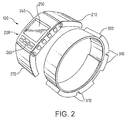
- FIG. 2 shows an exploded view of a wrist-mounted telephone apparatus 100 according to an embodiment of the invention.
- the telephone apparatus 100 comprises two parts: a detachable telephone part 200, and a strap or bracelet-like part 300 for attachment to a user's wrist.
- the telephone part 200 is shown separate from the strap part 300 for clarity. In reality, in the configuration shown, it would be located flush against the strap 300.
- the telephone part 200 comprises all the circuitry and elements normally associated with a portable radio telephone, as would be known by the skilled man.
- the telephone part comprises three major portions: an upper portion 210, a central portion 240 and a lower portion 270.
- a microphone element is positioned in the lower portion 270.
- a battery (not shown in Figure 2) is positioned in the lower portion also.
- An earpiece and antenna are positioned in the upper portion 210.
- the central portion 240 accommodates the bulk of the circuitry of the telephone, including a display 250, and a number of user-operable input keys 260. The keys are for controlling the operation of the telephone, and may be disposed on the front surface, as well as along one or more edges of the telephone 200.
- the telephone part 200 attaches firmly to the strap part 300.
- the user operates the release mechanism to free the telephone from the strap.
- the release mechanism can take many forms, and its exact operation is not critical to the operation of the invention.
- a release mechanism similar to that described in the aforementioned prior art document GB2317300B could be used.
- the mechanism therein described comprises two user-operable release latches which are situated on opposing edges of the telephone.
- the latches are arranged to engage with complementary parts on the bracelet and so lock the telephone to the bracelet.
- To remove the telephone part the user simply squeezes the two latches, which unlocks the telephone and allows it to be removed from the bracelet.
- To re-attach the telephone the user simply snaps the telephone back into position, and so re-engages the latches.
- the independently operable telephone part 200 contains a primary battery 280, positioned in the lower portion 270. This operates to provide the power for all the functions of the telephone part, but due to its necessarily small size, and hence relatively low power capacity, it can prove difficult to provide an operational or standby time which will meet the user's expectations.
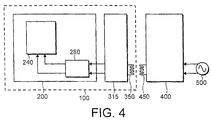
- the strap part 300 which remains attached to the user's wrist, is provided with a secondary power source (see Figure 4), which is operable to supplement the power of the primary source.
- the power in the telephone's primary battery is supplemented by using the secondary power source to recharge the battery 280 in the telephone.
- the secondary, or auxiliary, power source comprises a number of battery cells 315 which are electrically connected together and disposed in the enlarged portions 310 of the strap 300.
- the cells are connected together in the required number to make up a battery of the required capacity and voltage.
- Typical types of battery technology include Lithium-ion (Li-ion) and Nickel Metal Hydride (NiMH).
- a charging circuit which charges the primary power source using power derived from the auxiliary power source.
- the charging circuit may be disposed in either the telephone part 200 or the strap part 300.
- the charging circuitry can establish when the telephone part 200 is attached to the bracelet 300. If attachment is detected, the voltage or other status of the primary power source 280 is measured and, if below a defined threshold, charging is initiated.
- the primary power source 280 in the telephone part 200 may be kept to an acceptable size, whilst still being easily re-chargeable from a conveniently located source, i.e. the strap 300, which forms part of the usual means of carrying the telephone part.
- a bedside charger apparatus 400 is disclosed in Figure 3.
- Charger 400 connects to the normal domestic mains AC power supply (110V to 240V depending on location). It is primarily designed to be located at the user's bedside so that when the wrist mounted assembly 100 is removed at night, it can be inserted into slot 410 of charger 400 to re-charge the secondary power source overnight.
- Connection between the secondary power source and the charger 400 can be effected through the direct electrical connection, as is normal in currently available telephone charger arrangements.
- two conductive contacts could be disposed on a region of the bracelet 300. These contacts would connect internally with the secondary power source 315. Two sprung complementary contacts would then be provided in the slot 410 of the charger so that when the telephone 100 is inserted, the charging circuit is completed and the secondary power source can be charged.
- An alternative and preferred charging technique relies on an inductive coupling between the charger and the secondary power source.
- Charger 400 is connected to the mains AC supply 500.
- Charger 400 is equipped with a primary coil 450 of a transformer which is used to couple energy from the mains supply 500 to the secondary DC power source 315 via secondary coil 350.
- the two halves of the transformer 350, 450 are disposed adjacent one another, and so energy is inductively coupled from the primary coil 450 to the secondary coil 350, and so to the charging circuit forming part of the secondary power source 315.
- the secondary coil 350 can be disposed as a planar coil located just beneath the outer surface of one of the enlarged portions 310 of the bracelet part 300.
- the primary coil can then be located at the rear of the slot 410 of the charger so that when the telephone 100 is inserted, the two coils lie adjacent one another, thus ensuring maximum transfer of energy.
- Figure 4 also shows the power connections between the secondary source 315 and the primary source 280. These are shown as direct electrical connections, although these too could be implemented as an inductive coupling as previously described
- the present invention includes any novel feature or combination of features disclosed herein either explicitly or any generalisation thereof irrespective of whether or not it relates to the claimed invention or mitigates any or all of the problems addressed.
Landscapes
- Engineering & Computer Science (AREA)
- Computer Networks & Wireless Communication (AREA)
- Signal Processing (AREA)
- Telephone Set Structure (AREA)
- Telephone Function (AREA)
- Fittings On The Vehicle Exterior For Carrying Loads, And Devices For Holding Or Mounting Articles (AREA)
- Mobile Radio Communication Systems (AREA)
- Charge And Discharge Circuits For Batteries Or The Like (AREA)
- Eye Examination Apparatus (AREA)
Abstract
Description
According to the present invention, there is provided a portable telephone assembly comprising first and second portions wherein the first portion: comprises a primary power source; is independently operable as a portable telephone; and is arranged to be detachably connectable to the second portion, and the second portion: is arranged to be removably attachable to a user; and comprises an auxiliary power source operable to supplement the primary power source when the first and second portions are connected.
Claims (9)
- A portable telephone assembly comprising first and second portions wherein the first portion:and the second portion:comprises a primary power source;is independently operable as a portable telephone; andis arranged to be detachably connectable to the second portion,is arranged to be removably attachable to a user; andcomprises an auxiliary power source operable to supplement the primary power source when the first and second portions are connected.
- A portable telephone assembly as claimed in claim 1 wherein the auxiliary power source comprises a battery.
- A portable telephone assembly as claimed in claim 2 wherein the battery comprises several re-chargeable cells distributed about the second portion.
- A portable telephone assembly as claimed in any one of the preceding claims wherein the second portion is arranged for removable attachment to a user's wrist.
- A portable telephone assembly as claimed in any one of the preceding claims wherein charging circuitry is provided re-charge the primary power source from the auxiliary power source.
- A portable telephone assembly as claimed in claim 5 wherein the charging circuitry is disposed in the second portion.
- A portable telephone assembly as claimed in any one of claims 5 or 6 wherein the charging circuitry comprises contactless inductive charging apparatus.
- A portable telephone apparatus as claimed in any one of the preceding claims further comprising charging apparatus for re-charging the auxiliary power source.
- A portable telephone apparatus substantially as herein described and with particular reference to Figures 2 to 4 of the accompanying drawings.
Applications Claiming Priority (2)
| Application Number | Priority Date | Filing Date | Title |
|---|---|---|---|
| GB0101572A GB2371436B (en) | 2001-01-22 | 2001-01-22 | Portable telephone |
| GB0101572 | 2001-01-22 |
Publications (3)
| Publication Number | Publication Date |
|---|---|
| EP1225751A2 true EP1225751A2 (en) | 2002-07-24 |
| EP1225751A3 EP1225751A3 (en) | 2003-06-04 |
| EP1225751B1 EP1225751B1 (en) | 2008-07-30 |
Family
ID=9907229
Family Applications (1)
| Application Number | Title | Priority Date | Filing Date |
|---|---|---|---|
| EP02250174A Expired - Lifetime EP1225751B1 (en) | 2001-01-22 | 2002-01-10 | Portable telephone |
Country Status (7)
| Country | Link |
|---|---|
| US (1) | US6978160B2 (en) |
| EP (1) | EP1225751B1 (en) |
| JP (1) | JP2002281139A (en) |
| CN (1) | CN1253038C (en) |
| AT (1) | ATE403330T1 (en) |
| DE (1) | DE60227858D1 (en) |
| GB (1) | GB2371436B (en) |
Cited By (7)
| Publication number | Priority date | Publication date | Assignee | Title |
|---|---|---|---|---|
| WO2013074395A1 (en) * | 2011-11-16 | 2013-05-23 | Motorola Mobility Llc | Display device, corresponding systems, and methods therefor |
| EP2770399A1 (en) * | 2013-02-20 | 2014-08-27 | BlackBerry Limited | Multi-purpose interface for a portable electronic device |
| EP2998823A1 (en) * | 2014-09-16 | 2016-03-23 | LG Electronics Inc. | Mobile terminal |
| US9395696B2 (en) | 2013-02-20 | 2016-07-19 | Blackberry Limited | Multi-purpose interface for a portable electronic device |
| US9484001B2 (en) | 2013-12-23 | 2016-11-01 | Google Technology Holdings LLC | Portable electronic device controlling diffuse light source to emit light approximating color of object of user interest |
| US9622365B2 (en) | 2013-02-25 | 2017-04-11 | Google Technology Holdings LLC | Apparatus and methods for accommodating a display in an electronic device |
| US9674922B2 (en) | 2013-03-14 | 2017-06-06 | Google Technology Holdings LLC | Display side edge assembly and mobile device including same |
Families Citing this family (46)
| Publication number | Priority date | Publication date | Assignee | Title |
|---|---|---|---|---|
| USD572151S1 (en) * | 2000-07-25 | 2008-07-01 | Global Watch Industries Srl | Wrist watch with earphone/microphone |
| USD494556S1 (en) | 2002-03-01 | 2004-08-17 | Fossil, Inc. | Combined phone module and phone carriage |
| US7096048B2 (en) * | 2003-04-01 | 2006-08-22 | Sanders Donald T | Portable communications device |
| USD508738S1 (en) * | 2003-07-14 | 2005-08-23 | Motorola, Inc. | Wrist worn sensor platform |
| USD507550S1 (en) * | 2004-05-05 | 2005-07-19 | Samsung Electronics Co., Ltd. | Portable telephone |
| USD508031S1 (en) * | 2004-05-05 | 2005-08-02 | Samsung Electronics Co., Ltd. | Portable telephone |
| GB2416953A (en) * | 2004-08-06 | 2006-02-08 | John Timothy Greaves | Mobile telephone accommodates headset for recharging |
| EP1842391A1 (en) * | 2005-01-04 | 2007-10-10 | Global Watch Industries Srl | Wristwatch with earphone function |
| US7509094B2 (en) * | 2005-06-30 | 2009-03-24 | Modu Ltd. | Wireless telecommunication device and uses thereof |
| USD543192S1 (en) * | 2005-10-21 | 2007-05-22 | Lg Electronics Inc. | Watch shaped cellular phone |
| USD565427S1 (en) * | 2006-01-20 | 2008-04-01 | Hourpower Watches, Llc | Combined watch and telephone |
| GB2439362A (en) * | 2006-06-19 | 2007-12-27 | Edward Nuttall | Detachable mobile phone wristwatch |
| US7807511B2 (en) * | 2006-11-17 | 2010-10-05 | Freescale Semiconductor, Inc. | Method of packaging a device having a multi-contact elastomer connector contact area and device thereof |
| US7588951B2 (en) * | 2006-11-17 | 2009-09-15 | Freescale Semiconductor, Inc. | Method of packaging a semiconductor device and a prefabricated connector |
| US7696016B2 (en) * | 2006-11-17 | 2010-04-13 | Freescale Semiconductor, Inc. | Method of packaging a device having a tangible element and device thereof |
| US8391921B2 (en) | 2007-02-13 | 2013-03-05 | Google Inc. | Modular wireless communicator |
| US7970433B2 (en) | 2007-06-08 | 2011-06-28 | Modu Ltd. | SD switch box in a cellular handset |
| US10027789B2 (en) | 2007-02-13 | 2018-07-17 | Google Llc | Modular wireless communicator |
| US8412226B2 (en) | 2008-06-24 | 2013-04-02 | Google Inc. | Mobile phone locator |
| KR200451973Y1 (en) * | 2009-03-24 | 2011-01-25 | 주식회사 이노디자인 | Mobile terminal that can be easily attached to or detached from the wrist |
| US20110031289A1 (en) * | 2009-08-10 | 2011-02-10 | Robert Haskell | Wrist worn electronic device holder |
| USD617661S1 (en) * | 2009-11-13 | 2010-06-15 | Casio Keisanki Kabushiki Kaisha | Wrist watch |
| TW201120790A (en) * | 2009-12-03 | 2011-06-16 | Univ Nat Yang Ming | A system and a method for sensing physical signals with unlimited operation time and place |
| JP5388300B2 (en) * | 2010-01-29 | 2014-01-15 | リズム時計工業株式会社 | Watch movement |
| US8974349B2 (en) * | 2010-11-01 | 2015-03-10 | Nike, Inc. | Wearable device assembly having athletic functionality |
| US9011292B2 (en) | 2010-11-01 | 2015-04-21 | Nike, Inc. | Wearable device assembly having athletic functionality |
| US8249547B1 (en) | 2011-06-16 | 2012-08-21 | Albert Fellner | Emergency alert device with mobile phone |
| CN103995565B (en) * | 2013-02-20 | 2017-07-07 | 黑莓有限公司 | For the multifunctional ports of portable electric appts |
| US20150138699A1 (en) | 2013-11-15 | 2015-05-21 | Semiconductor Energy Laboratory Co., Ltd. | Electronic device |
| CN103633706A (en) * | 2013-12-11 | 2014-03-12 | 黄添添 | Wireless rechargeable electronic bracelet and wireless charging method thereof |
| JP1537616S (en) * | 2014-01-22 | 2018-10-22 | ||
| JP1536636S (en) * | 2014-01-22 | 2018-10-22 | ||
| USD742875S1 (en) * | 2014-01-27 | 2015-11-10 | Lg Electronics Inc. | Mobile phone |
| CN104898769B (en) * | 2014-03-03 | 2018-08-10 | 联想(北京)有限公司 | A kind of wearable electronic equipment |
| TWD165563S (en) * | 2014-04-08 | 2015-01-21 | 緯創資通股份有限公司 | Portion of wearable electronic device |
| JP1536548S (en) * | 2014-08-25 | 2015-11-02 | ||
| JP1562048S (en) * | 2014-08-25 | 2016-10-31 | ||
| JP1537085S (en) * | 2014-08-25 | 2015-11-02 | ||
| JP1536549S (en) * | 2014-08-25 | 2015-11-02 | ||
| CN105807645B (en) * | 2014-12-31 | 2018-12-14 | 联想(北京)有限公司 | A kind of method for controlling power supply and electronic equipment |
| EP3101508B1 (en) * | 2015-05-22 | 2020-04-08 | Lg Electronics Inc. | Wearable smart device |
| US9571147B1 (en) * | 2016-01-26 | 2017-02-14 | Chi-Yuan Chang | Portable storage buckling unit |
| KR102680702B1 (en) * | 2016-06-14 | 2024-07-03 | 삼성전자주식회사 | Strap and Electronic device including the same |
| US9800719B1 (en) * | 2017-07-11 | 2017-10-24 | Premergy, Inc. | Systems and methods for managing power for a mobile device |
| CN108574324B (en) * | 2018-03-27 | 2021-09-14 | 努比亚技术有限公司 | Power management method, wearable device and storage medium |
| CN112486250B (en) * | 2019-09-12 | 2024-06-14 | 万魔声学股份有限公司 | Wearable smart terminal devices |
Family Cites Families (18)
| Publication number | Priority date | Publication date | Assignee | Title |
|---|---|---|---|---|
| DE4310873C2 (en) * | 1993-04-02 | 1995-11-16 | Rainer Lauterbach | Cordless, removable headset |
| DE4319763C2 (en) | 1993-06-15 | 1995-08-31 | Glas Keil Gmbh & Co Kg | Evacuated, opaque multi-pane insulation panel |
| JPH089002A (en) | 1994-06-17 | 1996-01-12 | Mimasu Kinzoku Seisakusho:Kk | Portable communication equipment |
| US5857148A (en) * | 1995-06-13 | 1999-01-05 | Motorola, Inc. | Portable electronic device and method for coupling power thereto |
| KR19990028636A (en) * | 1995-07-05 | 1999-04-15 | 모토로라, 인크 | Conformal power supply |
| GB2317300B (en) * | 1996-09-12 | 2000-08-16 | Nokia Mobile Phones Ltd | A handset |
| US6043626A (en) * | 1996-10-29 | 2000-03-28 | Ericsson Inc. | Auxiliary battery holder with multicharger functionality |
| US6035035A (en) * | 1996-12-19 | 2000-03-07 | Classicom, Llc | Wrist mounted telephone device |
| JP3198961B2 (en) * | 1997-02-10 | 2001-08-13 | 日本電気株式会社 | Battery pack and portable communication device with built-in battery pack |
| US6006116A (en) * | 1997-10-08 | 1999-12-21 | Lucent Technologies, Inc. | Time-division radio that is powered by a low-power energy source |
| DE19803602C1 (en) * | 1998-01-30 | 1999-08-12 | Ingo Rennert | Mobile radio telephone with transport arrangement |
| US6275681B1 (en) * | 1998-04-16 | 2001-08-14 | Motorola, Inc. | Wireless electrostatic charging and communicating system |
| US6158884A (en) * | 1998-06-26 | 2000-12-12 | Motorola, Inc. | Integrated communicative watch |
| KR100313145B1 (en) * | 1998-11-06 | 2001-11-07 | 윤종용 | Watch type portable radiotelephone |
| JP2001103536A (en) * | 1999-09-03 | 2001-04-13 | Nokia Mobile Phones Ltd | Wrist watch type portable communication terminal |
| JP2001103538A (en) | 1999-09-29 | 2001-04-13 | Hitachi Kokusai Electric Inc | Wireless landline system |
| US6192253B1 (en) * | 1999-10-06 | 2001-02-20 | Motorola, Inc. | Wrist-carried radiotelephone |
| US6473630B1 (en) * | 1999-10-22 | 2002-10-29 | Sony Corporation | Method and apparatus for powering a wireless headset used with a personal electronic device |
-
2001
- 2001-01-22 GB GB0101572A patent/GB2371436B/en not_active Expired - Fee Related
-
2002
- 2002-01-10 AT AT02250174T patent/ATE403330T1/en not_active IP Right Cessation
- 2002-01-10 DE DE60227858T patent/DE60227858D1/en not_active Expired - Lifetime
- 2002-01-10 EP EP02250174A patent/EP1225751B1/en not_active Expired - Lifetime
- 2002-01-14 US US10/043,109 patent/US6978160B2/en not_active Expired - Lifetime
- 2002-01-21 JP JP2002011248A patent/JP2002281139A/en active Pending
- 2002-01-21 CN CNB02102426XA patent/CN1253038C/en not_active Expired - Fee Related
Cited By (10)
| Publication number | Priority date | Publication date | Assignee | Title |
|---|---|---|---|---|
| WO2013074395A1 (en) * | 2011-11-16 | 2013-05-23 | Motorola Mobility Llc | Display device, corresponding systems, and methods therefor |
| US9875008B2 (en) | 2011-11-16 | 2018-01-23 | Google Llc | Display device, corresponding systems, and methods therefor |
| US10387020B2 (en) | 2011-11-16 | 2019-08-20 | Google Technology Holdings LLC | Display device, corresponding systems, and methods therefor |
| EP2770399A1 (en) * | 2013-02-20 | 2014-08-27 | BlackBerry Limited | Multi-purpose interface for a portable electronic device |
| US9395696B2 (en) | 2013-02-20 | 2016-07-19 | Blackberry Limited | Multi-purpose interface for a portable electronic device |
| US9622365B2 (en) | 2013-02-25 | 2017-04-11 | Google Technology Holdings LLC | Apparatus and methods for accommodating a display in an electronic device |
| US9674922B2 (en) | 2013-03-14 | 2017-06-06 | Google Technology Holdings LLC | Display side edge assembly and mobile device including same |
| US9484001B2 (en) | 2013-12-23 | 2016-11-01 | Google Technology Holdings LLC | Portable electronic device controlling diffuse light source to emit light approximating color of object of user interest |
| EP2998823A1 (en) * | 2014-09-16 | 2016-03-23 | LG Electronics Inc. | Mobile terminal |
| US9612623B2 (en) | 2014-09-16 | 2017-04-04 | Lg Electronics Inc. | Mobile terminal |
Also Published As
| Publication number | Publication date |
|---|---|
| US20020103014A1 (en) | 2002-08-01 |
| DE60227858D1 (en) | 2008-09-11 |
| ATE403330T1 (en) | 2008-08-15 |
| JP2002281139A (en) | 2002-09-27 |
| CN1253038C (en) | 2006-04-19 |
| GB0101572D0 (en) | 2001-03-07 |
| EP1225751B1 (en) | 2008-07-30 |
| GB2371436B (en) | 2004-09-08 |
| CN1367630A (en) | 2002-09-04 |
| US6978160B2 (en) | 2005-12-20 |
| GB2371436A (en) | 2002-07-24 |
| EP1225751A3 (en) | 2003-06-04 |
Similar Documents
| Publication | Publication Date | Title |
|---|---|---|
| US6978160B2 (en) | Two part portable telephone configured to be worn about the person | |
| CN100409532C (en) | Portable instrument with wrist strap provided with electrical connection | |
| US9800084B2 (en) | Solar powered case for charging electronic devices | |
| EP1225750A2 (en) | Portable telephone | |
| US20180337542A1 (en) | Wearable power supply and hand worn mobile device having the same | |
| EP2685542B1 (en) | Mobile charger | |
| CN102456936A (en) | Wireless charging system, battery and electronic device with wireless charging function | |
| JP3907723B2 (en) | Battery pack | |
| JP2015159664A (en) | Power supply device for portable device and charging device of the same | |
| US10069317B2 (en) | Wearable power supply and hand worn mobile device having the same | |
| CN204631448U (en) | Can positive and negatively wearing a wrist watch of intelligent and traditional double-sided display | |
| JP2003306819A (en) | Belt housing battery | |
| CN206422572U (en) | Intelligent watch charger baby and the intelligent watch charged with the charger baby | |
| CN104701957A (en) | Wireless charging wristband for smart watch | |
| JP3996171B2 (en) | Battery pack lid providing non-contact charging interface and mobile phone including the battery pack lid | |
| JPH06350506A (en) | Wristwatch-shaped wireless telephone | |
| WO2009155698A1 (en) | Solar panel battery charger for electrical device | |
| CN207782914U (en) | Solar energy radio charge mobile phone shell and mobile phone | |
| KR20160149114A (en) | Wearable terminal auxiliary battery band | |
| CN212677359U (en) | Bluetooth headset charging box | |
| CN204812423U (en) | bracelet with charging function | |
| JP3957152B2 (en) | Wristwatch type transmitter | |
| KR20060009111A (en) | Holster charger and portable terminal | |
| WO2014067026A1 (en) | Slide rail-type back-mounted power supply | |
| CN112040365A (en) | Portable wireless earphone |
Legal Events
| Date | Code | Title | Description |
|---|---|---|---|
| PUAI | Public reference made under article 153(3) epc to a published international application that has entered the european phase |
Free format text: ORIGINAL CODE: 0009012 |
|
| AK | Designated contracting states |
Kind code of ref document: A2 Designated state(s): AT BE CH CY DE DK ES FI FR GB GR IE IT LI LU MC NL PT SE TR |
|
| AX | Request for extension of the european patent |
Free format text: AL;LT;LV;MK;RO;SI |
|
| PUAL | Search report despatched |
Free format text: ORIGINAL CODE: 0009013 |
|
| AK | Designated contracting states |
Designated state(s): AT BE CH CY DE DK ES FI FR GB GR IE IT LI LU MC NL PT SE TR |
|
| AX | Request for extension of the european patent |
Extension state: AL LT LV MK RO SI |
|
| 17P | Request for examination filed |
Effective date: 20031204 |
|
| AKX | Designation fees paid |
Designated state(s): AT BE CH CY DE DK ES FI FR GB GR IE IT LI LU MC NL PT SE TR |
|
| AXX | Extension fees paid |
Extension state: MK Payment date: 20031204 Extension state: LT Payment date: 20031204 Extension state: SI Payment date: 20031204 Extension state: AL Payment date: 20031204 Extension state: LV Payment date: 20031204 Extension state: RO Payment date: 20031204 |
|
| 17Q | First examination report despatched |
Effective date: 20050217 |
|
| 17Q | First examination report despatched |
Effective date: 20050217 |
|
| GRAP | Despatch of communication of intention to grant a patent |
Free format text: ORIGINAL CODE: EPIDOSNIGR1 |
|
| GRAS | Grant fee paid |
Free format text: ORIGINAL CODE: EPIDOSNIGR3 |
|
| GRAA | (expected) grant |
Free format text: ORIGINAL CODE: 0009210 |
|
| RBV | Designated contracting states (corrected) |
Designated state(s): AT BE CH CY DE DK ES FI FR GR IE IT LI LU MC NL PT SE TR |
|
| AK | Designated contracting states |
Kind code of ref document: B1 Designated state(s): AT BE CH CY DE DK ES FI FR GR IE IT LI LU MC NL PT SE TR |
|
| AX | Request for extension of the european patent |
Extension state: AL LT LV MK RO SI |
|
| REG | Reference to a national code |
Ref country code: CH Ref legal event code: EP |
|
| REF | Corresponds to: |
Ref document number: 60227858 Country of ref document: DE Date of ref document: 20080911 Kind code of ref document: P |
|
| REG | Reference to a national code |
Ref country code: IE Ref legal event code: FG4D |
|
| LTIE | Lt: invalidation of european patent or patent extension |
Effective date: 20080730 |
|
| PG25 | Lapsed in a contracting state [announced via postgrant information from national office to epo] |
Ref country code: NL Free format text: LAPSE BECAUSE OF FAILURE TO SUBMIT A TRANSLATION OF THE DESCRIPTION OR TO PAY THE FEE WITHIN THE PRESCRIBED TIME-LIMIT Effective date: 20080730 Ref country code: PT Free format text: LAPSE BECAUSE OF FAILURE TO SUBMIT A TRANSLATION OF THE DESCRIPTION OR TO PAY THE FEE WITHIN THE PRESCRIBED TIME-LIMIT Effective date: 20081230 Ref country code: ES Free format text: LAPSE BECAUSE OF FAILURE TO SUBMIT A TRANSLATION OF THE DESCRIPTION OR TO PAY THE FEE WITHIN THE PRESCRIBED TIME-LIMIT Effective date: 20081110 |
|
| PG25 | Lapsed in a contracting state [announced via postgrant information from national office to epo] |
Ref country code: FI Free format text: LAPSE BECAUSE OF FAILURE TO SUBMIT A TRANSLATION OF THE DESCRIPTION OR TO PAY THE FEE WITHIN THE PRESCRIBED TIME-LIMIT Effective date: 20080730 Ref country code: AT Free format text: LAPSE BECAUSE OF FAILURE TO SUBMIT A TRANSLATION OF THE DESCRIPTION OR TO PAY THE FEE WITHIN THE PRESCRIBED TIME-LIMIT Effective date: 20080730 |
|
| PG25 | Lapsed in a contracting state [announced via postgrant information from national office to epo] |
Ref country code: BE Free format text: LAPSE BECAUSE OF FAILURE TO SUBMIT A TRANSLATION OF THE DESCRIPTION OR TO PAY THE FEE WITHIN THE PRESCRIBED TIME-LIMIT Effective date: 20080730 |
|
| PG25 | Lapsed in a contracting state [announced via postgrant information from national office to epo] |
Ref country code: DK Free format text: LAPSE BECAUSE OF FAILURE TO SUBMIT A TRANSLATION OF THE DESCRIPTION OR TO PAY THE FEE WITHIN THE PRESCRIBED TIME-LIMIT Effective date: 20080730 |
|
| PLBE | No opposition filed within time limit |
Free format text: ORIGINAL CODE: 0009261 |
|
| STAA | Information on the status of an ep patent application or granted ep patent |
Free format text: STATUS: NO OPPOSITION FILED WITHIN TIME LIMIT |
|
| 26N | No opposition filed |
Effective date: 20090506 |
|
| PG25 | Lapsed in a contracting state [announced via postgrant information from national office to epo] |
Ref country code: MC Free format text: LAPSE BECAUSE OF NON-PAYMENT OF DUE FEES Effective date: 20090131 Ref country code: IT Free format text: LAPSE BECAUSE OF FAILURE TO SUBMIT A TRANSLATION OF THE DESCRIPTION OR TO PAY THE FEE WITHIN THE PRESCRIBED TIME-LIMIT Effective date: 20080730 |
|
| REG | Reference to a national code |
Ref country code: CH Ref legal event code: PL |
|
| PG25 | Lapsed in a contracting state [announced via postgrant information from national office to epo] |
Ref country code: LI Free format text: LAPSE BECAUSE OF NON-PAYMENT OF DUE FEES Effective date: 20090131 Ref country code: CH Free format text: LAPSE BECAUSE OF NON-PAYMENT OF DUE FEES Effective date: 20090131 |
|
| PG25 | Lapsed in a contracting state [announced via postgrant information from national office to epo] |
Ref country code: IE Free format text: LAPSE BECAUSE OF NON-PAYMENT OF DUE FEES Effective date: 20090110 Ref country code: SE Free format text: LAPSE BECAUSE OF FAILURE TO SUBMIT A TRANSLATION OF THE DESCRIPTION OR TO PAY THE FEE WITHIN THE PRESCRIBED TIME-LIMIT Effective date: 20081030 |
|
| PG25 | Lapsed in a contracting state [announced via postgrant information from national office to epo] |
Ref country code: GR Free format text: LAPSE BECAUSE OF FAILURE TO SUBMIT A TRANSLATION OF THE DESCRIPTION OR TO PAY THE FEE WITHIN THE PRESCRIBED TIME-LIMIT Effective date: 20081031 |
|
| PG25 | Lapsed in a contracting state [announced via postgrant information from national office to epo] |
Ref country code: LU Free format text: LAPSE BECAUSE OF NON-PAYMENT OF DUE FEES Effective date: 20090110 |
|
| PGFP | Annual fee paid to national office [announced via postgrant information from national office to epo] |
Ref country code: FR Payment date: 20110128 Year of fee payment: 10 Ref country code: DE Payment date: 20110105 Year of fee payment: 10 |
|
| PG25 | Lapsed in a contracting state [announced via postgrant information from national office to epo] |
Ref country code: TR Free format text: LAPSE BECAUSE OF FAILURE TO SUBMIT A TRANSLATION OF THE DESCRIPTION OR TO PAY THE FEE WITHIN THE PRESCRIBED TIME-LIMIT Effective date: 20080730 |
|
| PG25 | Lapsed in a contracting state [announced via postgrant information from national office to epo] |
Ref country code: CY Free format text: LAPSE BECAUSE OF FAILURE TO SUBMIT A TRANSLATION OF THE DESCRIPTION OR TO PAY THE FEE WITHIN THE PRESCRIBED TIME-LIMIT Effective date: 20080730 |
|
| REG | Reference to a national code |
Ref country code: FR Ref legal event code: ST Effective date: 20120928 |
|
| PG25 | Lapsed in a contracting state [announced via postgrant information from national office to epo] |
Ref country code: DE Free format text: LAPSE BECAUSE OF NON-PAYMENT OF DUE FEES Effective date: 20120801 |
|
| REG | Reference to a national code |
Ref country code: DE Ref legal event code: R119 Ref document number: 60227858 Country of ref document: DE Effective date: 20120801 |
|
| PG25 | Lapsed in a contracting state [announced via postgrant information from national office to epo] |
Ref country code: FR Free format text: LAPSE BECAUSE OF NON-PAYMENT OF DUE FEES Effective date: 20120131 |