EP1225739A1 - Radio communication receiver - Google Patents
Radio communication receiver Download PDFInfo
- Publication number
- EP1225739A1 EP1225739A1 EP01915682A EP01915682A EP1225739A1 EP 1225739 A1 EP1225739 A1 EP 1225739A1 EP 01915682 A EP01915682 A EP 01915682A EP 01915682 A EP01915682 A EP 01915682A EP 1225739 A1 EP1225739 A1 EP 1225739A1
- Authority
- EP
- European Patent Office
- Prior art keywords
- frequency offset
- estimation
- unit
- correction
- value
- Prior art date
- Legal status (The legal status is an assumption and is not a legal conclusion. Google has not performed a legal analysis and makes no representation as to the accuracy of the status listed.)
- Withdrawn
Links
Images



Classifications
-
- H—ELECTRICITY
- H04—ELECTRIC COMMUNICATION TECHNIQUE
- H04L—TRANSMISSION OF DIGITAL INFORMATION, e.g. TELEGRAPHIC COMMUNICATION
- H04L27/00—Modulated-carrier systems
- H04L27/0014—Carrier regulation
-
- H—ELECTRICITY
- H04—ELECTRIC COMMUNICATION TECHNIQUE
- H04L—TRANSMISSION OF DIGITAL INFORMATION, e.g. TELEGRAPHIC COMMUNICATION
- H04L27/00—Modulated-carrier systems
- H04L27/0014—Carrier regulation
- H04L2027/0044—Control loops for carrier regulation
- H04L2027/0046—Open loops
-
- H—ELECTRICITY
- H04—ELECTRIC COMMUNICATION TECHNIQUE
- H04L—TRANSMISSION OF DIGITAL INFORMATION, e.g. TELEGRAPHIC COMMUNICATION
- H04L27/00—Modulated-carrier systems
- H04L27/0014—Carrier regulation
- H04L2027/0044—Control loops for carrier regulation
- H04L2027/0053—Closed loops
- H04L2027/0055—Closed loops single phase
-
- H—ELECTRICITY
- H04—ELECTRIC COMMUNICATION TECHNIQUE
- H04L—TRANSMISSION OF DIGITAL INFORMATION, e.g. TELEGRAPHIC COMMUNICATION
- H04L27/00—Modulated-carrier systems
- H04L27/0014—Carrier regulation
- H04L2027/0044—Control loops for carrier regulation
- H04L2027/0063—Elements of loops
- H04L2027/0065—Frequency error detectors
-
- H—ELECTRICITY
- H04—ELECTRIC COMMUNICATION TECHNIQUE
- H04L—TRANSMISSION OF DIGITAL INFORMATION, e.g. TELEGRAPHIC COMMUNICATION
- H04L27/00—Modulated-carrier systems
- H04L27/0014—Carrier regulation
- H04L2027/0083—Signalling arrangements
- H04L2027/0089—In-band signals
- H04L2027/0093—Intermittant signals
- H04L2027/0095—Intermittant signals in a preamble or similar structure
-
- H—ELECTRICITY
- H04—ELECTRIC COMMUNICATION TECHNIQUE
- H04L—TRANSMISSION OF DIGITAL INFORMATION, e.g. TELEGRAPHIC COMMUNICATION
- H04L25/00—Baseband systems
- H04L25/02—Details ; arrangements for supplying electrical power along data transmission lines
- H04L25/0202—Channel estimation
- H04L25/0212—Channel estimation of impulse response
- H04L25/0216—Channel estimation of impulse response with estimation of channel length
Definitions
- the present invention relates to a receiver which can be applied to a wireless communication for example in automobile telephones, portable telephones, cordless telephones.
- this invention relates to a wireless communication receiver having a frequency offset correction function.
- a conventional wireless communication receiver will be described below.
- a transmitter generates a signal which executes channel encoding to information data including data obtained by encoding voice, data of the internet, and the like and which transmits the resultant information data.
- the signal is modulated, up-conversion is executed on the basis of a frequency generated by a local oscillator.
- the transmitted signal obtained here is transmitted through an antenna.
- the transmitted signal is received by a receiver through an antenna, and is down-converted on the basis of a frequency generated by a local oscillator.
- the down-converted received signal is converted into a digital received signal (to be referred to as a received signal hereinafter) by an analog/digital converter.
- the offset of the frequencies i.e., the frequency offset causes the received signal to be distorted. For this reason, in order to realize communication having high quality, the frequency offset must be corrected.
- distortion of the received signal may be generated by frequency selective fading caused by intersymbol interference.
- the receiver must perform a correction process for the frequency offset and a demodulation process in consideration of the intersymbol interference.
- an automatic frequency control circuit (to be referred to as a conventional receiver hereinafter) described in Japanese Patent Application Laid-Open No. 10-163816.
- the transmission device repeatedly transmits the pattern of a fixed PN signal as a preamble pattern, and the receiver calculates a phase deviation per symbol on the basis of the component of a PN signal which is demodulated in a preamble period and which is obtained one cycle before and the signal component of a present PN code.
- a conventional receiver performs correction of a phase in units of symbols in a data period on the basis of the phase deviation.
- correction of the phases is performed on the basis of the phase deviation calculated by using the preamble pattern.
- the preamble period is elongated to improve an estimated precision of the frequency offset
- the estimated precision of the frequency offset is deteriorated.
- communication quality is deteriorated disadvantageously.
- a wireless communication receiver comprises: a frequency offset correction value estimation unit (corresponding to a frequency offset correction value estimation section 21 according to an embodiment to be described later) which receives a signal including a predetermined fixed pattern from a transmission side, thereafter, selects a combination of fixed patterns used in an estimation process of a frequency offset depending on the state of a channel, and outputs an estimation result of the frequency offset calculated by using the combination of the fixed patterns as a correction value of a determined frequency offset; a frequency offset correction unit (corresponding to a frequency offset correction section 22) which corrects a frequency offset of a received signal on the basis of the correction value; and an equalizer (corresponding to an equalizer 23) which receives the received signal obtained after the correction is performed and which demodulates the received signal by using a predetermined algorithm.
- a frequency offset correction value estimation unit corresponding to a frequency offset correction value estimation section 21 according to an embodiment to be described later
- the wireless communication receiver further comprises: an averaging unit (corresponding to an averaging section 51) which averages calculated correction values calculated the predetermined number of times by the frequency offset correction value estimation unit; and a feedback correction unit (corresponding to a frequency offset correction section 52) which feeds back the averaging result to correct a frequency offset of subsequent received signals.
- the frequency offset correction unit corrects a frequency offset component which cannot be corrected by the feedback correction unit.
- the wireless communication receiver further comprises an averaging unit which averages correction values calculated the predetermined number of times by the frequency offset correction value estimation unit.
- An oscillator on a reception side is directly controlled on the basis of the averaging result to correct a frequency offset of subsequent received signals, and the frequency offset correction unit correct a frequency offset component which cannot be corrected by the oscillator.
- the wireless communication receiver next comprises: a frequency offset correction value estimation unit (corresponding to a frequency offset correction value estimation section 21) which receives a signal including a predetermined fixed pattern from a transmission side, thereafter, selects a combination of fixed patterns used in an estimation process of a frequency offset depending on the state of a channel, and outputs an estimation result of the frequency offset calculated by using the combination of the fixed patterns as a correction value of a determined frequency offset; an averaging unit (corresponding to an averaging section 51) which averages correction values calculated the predetermined number of times by the frequency offset correction value estimation unit; a feedback correction unit (corresponding to a frequency offset correction section 52) which feeds back the averaging result to correct a frequency offset of subsequent received signals; and an equalizer (corresponding to an equalizer 23) which receives the received signal obtained after the correction is performed and which demodulates the received signal by using a predetermined algorithm.
- a frequency offset correction value estimation unit corresponding to a frequency offset correction value estimation section 21
- the wireless communication receiver comprises : a frequency offset correction value estimation unit (corresponding to frequency offset correction value estimation sections 21a, ..., 21b) of P (arbitrary number) series which receive signals including predetermined fixed patterns from a transmission side, thereafter, select combinations of fixed patterns used in estimation processes of frequency offsets depending on the state of a channel, and output estimation results of the frequency offsets calculated by using the combinations of the fixed patterns as correction values of determined frequency offsets; a combining unit (corresponding to a combining section 24) which averages the P correction values to output an averaging result as a correction value of a frequency offset being common to the respective series; a frequency offset correction unit (corresponding to frequency offset correction sections 22a, ..., 22b) of P series which correct frequency offsets of received signals on the basis of the common correction value; and an equalizer (corresponding to an equalizer 23a) which receives P received signals obtained after the correction is performed and which demodulates the received signals by using a predetermined algorithm.
- a frequency offset correction value estimation unit corresponding to frequency offset correction value estimation sections 21
- the wireless communication receiver further comprises: an averaging unit (corresponding to an averaging section 51) which averages correction values calculated the predetermined number of times by the combining unit; and a feedback correction unit (corresponding to frequency offset correction sections 52a, ..., 52b) of P series which feed back the averaging result to correct frequency offset of subsequent received signals.
- the frequency offset correction unit of P series correct frequency offset components which cannot be corrected by the feedback correction unit of P series, respectively.
- the wireless communication receiver further comprises an averaging unit which averages correction values calculated the predetermined number of times by the combining unit.
- An oscillator on a reception side is directly controlled on the basis of the averaging result to correct a frequency offset of subsequent received signals, and the frequency offset correction unit of P series correct frequency offset components which cannot be corrected by the oscillator, respectively.
- the wireless communication receiver comprises : a frequency offset correction value estimation unit (corresponding to frequency offset correction value estimation sections 21a, ..., 21b) of P (arbitrary number) series which receive signals including predetermined fixed patterns from a transmission side, thereafter, select combinations of fixed patterns used in estimation processes of frequency offsets depending on the state of a channel, and output estimation results of the frequency offsets calculated by using the combinations of the fixed patterns as correction values of determined frequency offsets; a combining unit (corresponding to combining section 24) which averages the P correction values to output an averaging result as a correction value of a frequency offset being common to the respective series; an averaging unit (corresponding to an averaging section 51) which averages correction values calculated the predetermined number of times by the combining unit; a feedback correction unit (corresponding to frequency offset correction sections 52a, ..., 52b) of P series which feed back the averaging result to correct frequency offset of subsequent received signals; and an equalizer (corresponding to an equalizer 23a) which receives Preceived signals obtained after the
- the frequency offset correction value estimation unit comprises: a first frequency offset estimation unit (corresponding to a first frequency offset estimation section 31) which estimates a frequency offset of a received signal by using the same fixed patterns located at different positions; a second frequency offset estimation unit (corresponding to a second frequency offset estimation section 32) which estimates a frequency offset of a received signal by using the same fixed patterns which are different from the fixed patterns used in the first frequency offset estimation unit and located at different positions; an estimation value selection unit (corresponding to an estimation scheme selection section 33) which selects any one of the estimation values of the frequency offsets depending on a state of a channel; and an estimation value switching unit (corresponding to a correction value switching section 34) which selects the outputs of the estimation values on the basis of the selection result.
- the estimation value selection unit comprises: a delay spread estimation unit (corresponding to a delay spread estimation section 41) which estimates an amount of delay of a channel by using a fixed pattern; anoise power estimation unit (corresponding to a noise power estimation section 42) which estimates a noise power by using a fixed pattern; and an estimation value decision unit (corresponding to an estimation scheme decision section 43) which decides the estimation value of one preferably selected frequency offset on the basis of the estimation value of the delay spread and the estimation value of the noise power.
- a delay spread estimation unit corresponding to a delay spread estimation section 41
- anoise power estimation unit corresponding to a noise power estimation section 42
- an estimation value decision unit corresponding to an estimation scheme decision section 43
- the estimation value selection unit comprises: a delay spread estimation unit which estimates an amount of delay of a channel by using a fixed pattern; and an estimation value decision unit which decides the estimation value of one preferably selected frequency offset on the basis of the estimation value of the delay spread.
- the delay spread estimation unit estimates powers in units of paths which arrive, calculates a threshold value on the basis of the powers of M (M is a natural number) paths including a path having the maximum power, and sets a range including a path having a power higher than the threshold value as an estimation value of a delay spread.
- the delay spread estimation unit estimates powers in units of paths which arrive, calculates a threshold value on the basis of the noise power, and sets a range including a path having a power higher than the threshold value as an estimation value of a delay spread.
- the delay spread estimation unit estimates powers in units of paths which arrive, calculates a threshold value on the basis of powers of M (M is a natural number) paths including a path having the maximum power or the noise power, and sets a range including a path having a power higher than the threshold value as an estimation value of a delay spread.
- Fig. 1 includes diagrams showing the configuration of a first embodiment of a receiver according to the present invention and the configuration of a conventional transmission device;
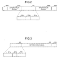
- Fig. 2 is a diagram showing an example of a transmission frame format generated by the transmission device;
- Fig. 3 is a diagram showing an example of a transmission frame format generated by the transmission device;
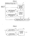
- Fig. 4 is a diagram showing the configuration of a demodulation unit of the first embodiment;
- Fig. 5 is a diagram showing a configuration of an estimation scheme selection unit;
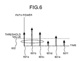
- Fig. 6 is a diagram showing a method of estimating a delay spread in a delay spread estimation unit;
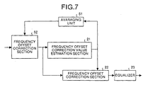
- Fig. 7 is a diagram showing the configuration of a demodulation unit in a second embodiment;
- Fig. 1 includes diagrams showing the configuration of a first embodiment of a receiver according to the present invention and the configuration of a conventional transmission device;
- Fig. 2 is a diagram showing an example of a transmission frame format generated by the transmission device;
- Fig. 3 is
- Fig. 8 is a diagram showing the configuration of a third embodiment of a receiver according to the present invention
- Fig. 9 is a diagram showing the configuration of a demodulation unit of the third embodiment
- Fig. 10 is a diagram showing a demodulation unit according to a fourth embodiment.
- Fig. 1 is a diagram showing the configuration (see Fig. 1(a) of a first embodiment of a wireless communication receiver (to be referred to as a receiver hereinafter) according to the present invention and the configuration (see Fig. 1(b)) of a conventional wireless communication receiver (to be referred to as a transmission device hereinafter).
- reference numeral 1 denotes a receiver
- reference numeral 2 denotes an antenna
- reference numeral 3 denotes an oscillator
- reference numeral 4 denotes a down-convert unit
- reference numeral 5 denotes an A/D conversion unit
- reference numeral 6 denotes a demodulation unit
- reference numeral 7 denotes an error correction unit.
- Fig. 1 denotes a receiver
- reference numeral 3 denotes an oscillator
- reference numeral 4 denotes a down-convert unit
- reference numeral 5 denotes an A/D conversion unit
- reference numeral 6 denotes a demodulation unit
- reference numeral 11 denotes a transmission device
- reference numeral 12 denotes a transmission data generation unit
- reference numeral 13 denotes a modulation unit
- reference numeral 14 denotes an oscillator
- reference numeral 15 denotes an up-convert unit
- reference numeral 16 denotes an antenna.
- the transmission data generation section 12 performs channel encoding to information data including data obtained by encoding voice, data of the internet, and the like to generate transmission data.
- the modulation unit 13 demodulates transmission data output from the transmission data generation section 12, and the up-convert unit 15 up-converts the modulated transmission data on the basis of a frequency generated by the oscillator 14 ant transmits the up-converted transmitted signal through the antenna 16.
- the transmitted signal is received through the antenna 2, and the down-convert section 4 down-converts the received signal on the basis of a frequency generated by the oscillator 3.
- the analog/digital conversion unit 5 (to be referred to as an A/D conversion unit 5 hereinafter) converts the down-converted analog signal into a digital signal (to be referred to as a received signal hereinafter), and the demodulation section 6 demodulates the A/D-converted received signal (the details of the demodulation section 6 which is the characteristic feature of the present invention will be described later).
- the error correction section 7 performs an error correction process such as a deinterleaving process and a decoding process to the demodulated signal
- Fig. 2 is a diagram showing an example of a transmission frame format generated by the transmission device 11.
- a training signal 201 is a known signal on the receiver 1 side, and is constituted by a fixed pattern 201a and a fixed pattern 201c and an arbitrary fixed pattern 201b interposed between the fixed pattern 201a and the fixed pattern 201c.
- an information signal 202a and an information signal 202b are present on both the sides of the training signal 201.
- On the outside of the information signal 202a and the information signal 202b a fixed pattern 203a and a fixed pattern 203b are present.
- the fixed pattern 201a and the fixed pattern 201c must be equal to each other, and the fixed pattern 203a and the fixed pattern 203b must be equal to each other.
- the fixed pattern 201b may not be arranged.
- a transmission frame format is expressed by:
- XX...XXX represents the information signals 202a and 202b
- "000" outside the information signals represents the fixed patterns 203a and 203b
- "0101110” inside the information signals represents the fixed patterns 201a and 201c
- "11010" at the center represents the arbitrary fixed pattern 201b.
- Fig. 3 is a diagram showing an example of a transmission frame format which is different from that in Fig. 2 and generated by the transmission device 11.
- the transmission frame is constituted by a training signal 301, an information signal 302, and a fixed pattern 303.
- the training signal 301 is a known signal on the receiver 1 side, and is constituted by fixed patterns 301a and 301c and an arbitrary fixed pattern 301b interposed between the fixed patterns 301a and 301c.
- the training signal 301 must partially include the same pattern as a fixed pattern 303.
- the arbitrary fixed pattern 301b may not be arranged.
- the transmission frame format shown in Fig. 3 can be expressed by:
- XX...XXX represents the information signal 302
- "000" on the right side of the information signal 302 represents the fixed pattern 303
- "0101100” on the left side of the information signal 302 represents the fixed pattern 301a and the fixed pattern 301c
- "01010" between the fixed pattern 301a and the fixed pattern 301c represents the arbitrary fixed pattern 301b.
- the training signal 301 includes "000" which is the same as the fixed pattern 303.
- Fig. 4 is a diagram showing the configuration of the demodulation section 6 according to the first embodiment.
- reference numeral 21 denotes a frequency offset correction value estimation unit
- reference numeral 22 denotes a frequency offset correction unit
- reference numeral 23 denotes an equalizer.
- reference numeral 31 denotes a first frequency offset estimation section
- reference numeral 32 denotes a second frequency offset estimation section
- reference numeral 33 denotes an estimation scheme selection section
- reference numeral 34 denotes a correction value switching section.
- reference symbol N11 denotes time corresponding to the start position of the fixed pattern 201a in a received signal r(n)
- reference symbol N13 denotes time corresponding to the start position of the fixed pattern 201c in the received signal r(n)
- reference symbol CONJG ⁇ r(N11 + i) ⁇ denotes a complex conjugation of a complex number r (N11 + i)
- reference symbol Re(F1) denotes the real part of a complex number F1
- reference symbol Im(F1) denotes an imaginary part of the complex number F1
- reference symbol arctan ⁇ Im(F1)/Re(F1) ⁇ denotes an arc tangent of a real number Im(F1)/Re(F1).
- reference symbol N1 denotes the lengths of the fixed patterns 201a and 201c
- reference symbol L represents a length corresponding to the maximum delay time of an effective delay wave generated in a channel.
- the value F1 calculated by Equation (1) represents a result obtained by composing an estimation value (complex number) of a phase rotation amount generated in symbols (N13 - N11) by a weight corresponding to the power of a received signal.
- the value f1 calculated by Equation (2) represents an estimation value (angle) of a phase rotation amount generated in one symbol.
- reference symbol N31 denotes time corresponding to the start position of the fixed pattern 203a in a received signal r(n)
- reference symbol N32 denotes time corresponding to the start position of the fixed pattern 203b in the received signal r(n)
- reference symbol N3 denotes the lengths of the fixed pattern 203a and 203b.
- the value F3 calculated by Equation (3) represents an estimation value (complex number) of a phase rotation amount generated in symbols (N32 - N31) .
- the value f3 calculated by Equation (4) represents an estimation value (angle) of a phase rotation amount generated in one symbol.
- the estimation scheme selection section 33 by using a training signal included in a received signal, any one of an estimation value of a frequency offset output from the first frequency offset estimation section 31 and an estimation value of a frequency offset output from the second frequency offset estimation section 32 is selected.
- the correction value switching section 34 on the basis of a selection result obtained by the estimation scheme selection section 33, an output is switched to any one of the estimation value of the frequency offset output from the first frequency offset estimation section 31 and the estimation value of the frequency offset output from the second frequency offset estimation section 32.
- One estimation value selected here is output to the subsequent frequency offset correction section 22 as a correction value.
- reference symbol j denotes the square root of (-1)
- reference symbol r'(n) denotes the corrected received signal
- reference symbol f denotes a correction value output from the correction value switching section 34.
- the received signal in which distortion caused by a frequency offset is corrected is received, and, thereafter, the received signal is demodulated in consideration of distortion caused by a multipath caused by frequency selective fading or the like.
- the demodulation result is output to the subsequent error correction section 7.
- the configuration of the equalizer 23 is not limited to the above configuration.
- Maximum-likelihood sequence estimation (MLSE: Maximum-Likelihood Sequence Estimation) which is a known technique, decision-feedback sequence estimation (DFSE: Decision-Feedback Sequence Estimation or DDFSE: Delayed Decision-Feedback Sequence Estimation), a decision-feedback equalizer (DFE: Decision-Feedback Equalizer), RSSE (Reduced-State Sequence Estimation), a list-output Viterbi equalizer (LVE: List-output Viterbi Equalizer), an equalizer using an M algorithm, an SOVA (Soft-Output Viterbi Algorithm), a soft-decision output equalizer using an algorithm such as MAP (Maximum a Posteriori), Max-log-MAP, or Log-MAP, an equalizer obtained by modifying these equalizers, or the like can be used.
- a Turbo Equalizer or an equalizer to which an error correction function is combined may be used.
- Fig. 5 is a diagram showing a configuration of the estimation scheme selection section 33.
- reference numeral denotes a delay spread estimation section
- reference numeral 42 denotes a noise power estimation section
- reference numeral 43 denotes an estimation scheme decision section.
- the delay spread estimation section 41 by using a training signal included in a received signal, delay time of the maximum effective delay wave of a channel is estimated, and the estimation result is output to the estimation scheme decision section 43 as delay spread time .
- the noise power estimation section 42 a noise power is estimated by using the training signal included in the received signal, and the estimation result is output to the estimation scheme decision section 43.
- the estimation scheme decision section 43 preferably selected one of the estimation value of the frequency offset output from the first frequency offset estimation section 31 and the estimation value of the frequency offset output from the second frequency offset estimation section 32 is decided on the basis of the received noise power estimation value and the delay spread estimation value.
- the estimation value of the output from the second frequency offset estimation section 32 can be estimated at a precision higher than that of the estimation value of the output from the first frequency offset estimation section 31 because the second frequency of f set estimation section 32 calculates the phase rotation amount generated in one symbol from the phase rotation amount generated in the symbols (N32 - N31).
- the estimation precision of the estimation value of the output from the second frequency offset estimation section 32 is deteriorated.
- the estimation value of the output from the other first frequency offset estimation section 31 can be estimated at a precision higher than that of the estimation value of the output from the second frequency offset estimation section 32.
- the estimation value of the frequency offset of the output from the first frequency offset estimation section 31 is selected. In the other case, the estimation value of the frequency offset of the output from the second frequency offset estimation section 32 is selected.
- Fig. 6 is a diagram showing a method of estimating a delay spread in the delay spread estimation section 41.
- reference numerals 601a, 601b, 601c, 601d, 601e, and 601f denote path powers, respectively, and reference numeral 602 denotes a threshold value of a power.
- path powers are estimated.
- the path powers 601a to 601f in Fig. 6 represent estimation results, respectively.
- the abscissa indicates time.
- the path power 601a is a power of a path which directly arrives
- the path power 601f is a power of a path having maximum delay time.
- the sum of the path powers 601a to 601c is calculated, and a value obtained by multiplying a fixed constant to the sum of powers is set as the threshold value 602.
- the range until a path having a power higher than the threshold value 602 is set as an amount of delay of the channel. In this manner, an accurate amount of delay can be known, and an apparent decision reference can be set in the estimation scheme decision section 43. For this reason, the estimation scheme selection section 33 can easily perform switching control of the correction value switching section 34 at a high precision.
- a value obtained by multiplying a fixed constant to a noise power calculated by the noise power estimation section 42 is set as the threshold value 602.
- the range until the path having a power higher than the threshold value can also be set as an amount of delay of the channel.
- the sum of the path powers 601a to 601c is compared with the noise power calculated by the noise power estimation section 42, and a value obtained by multiplying a fixed constant to larger one of the sum of the powers and the noise power is set as the threshold value 602.
- a range until a path having a power higher than the threshold value 602 may be set as the amount of delay of the channel.
- the estimation value of a frequency offset to be used is selected depending on communication conditions such as the state of a channel, and, on the basis of the estimation value of the selected frequency offset, a distortion depending on the frequency offset in the received signal is corrected. Even in a communication environment in which intersymbol interference caused by a multipath exists, preferable communication quality can be realized.
- calculation corresponding to Equation (2) and Equation (4) are actually performed by the frequency offset estimation units, respectively.
- the present invention is not limited to the embodiment.
- the present invention may also be realized by replacing the calculation results with a ROM table.
- both the frequency offset estimation units are operated as described above.
- the present invention is not limited to this embodiment.
- only one of the first frequency offset estimation section 31 and the second frequency offset estimation section 32 which is selected by the estimation scheme selection section 33 may be operated.
- the estimation scheme decision section 43 may decide an estimation value of a frequency offset to be used on the basis of only the estimation value of the delay spread. In contrast to this, the estimation value of the frequency offset to be used may be decided on the basis of only the estimation value of the noise power.
- the estimation value of the frequency offset may be selected by not only the state of the channel but also a frequency band to be used.
- an amount of frequency offset is increased in proportion to a frequency band to be used. For this reason, for example, when a higher frequency band is used, the estimation value of the frequency offset of the output from the first frequency offset estimation section 31 is used.
- the estimation value of the frequency offset of the output from the second frequency offset estimation section 32 is used. This is because, when a phase rotation amount generated by a frequency offset is large, and a phase rotation amount generated in the symbols (N32 - N31) exceeds ⁇ , the frequency offset cannot be precisely estimated by the second frequency offset estimation section 32.
- the frequency offset correction value estimation section 21 performs the processes of Equations (1) to (4).
- the present invention is not limited to the embodiment.
- the frequency offset correction value estimation section 21 performs the processes of Equations (1) and (3) to output an estimation value of a frequency offset of a complex number.
- the frequency offset correction section 22 may be performs the processes of Equations (2) and (4).
- Fig. 7 is a diagram showing the configuration of a second embodiment of a receiver according to the present invention. More specifically, Fig. 7 is a diagram showing the configuration of a demodulation section 6 in the second embodiment.
- reference numeral 51 denotes an averaging section
- reference numeral 52 denotes a frequency offset correction section.
- the other configuration is the same as that in Fig. 4 of the first embodiment described above. For this reason, the same reference numerals as in Fig. 4 denote the same parts in Fig. 7, and a description thereof will be omitted. Subsequently, in this embodiment, only parts which are different from the parts of the first embodiment described above will be described below.
- f(m) f(m - 1) + ⁇ f(m - 1)
- r'(n) r(n) ⁇ [cos ⁇ n ⁇ f(m) ⁇ -j ⁇ sin ⁇ n ⁇ f(m) ⁇ ]
- Equations (6) and (7) reference symbol ⁇ f(m) denotes a frequency offset correction value output from the averaging section 51 in the mth frame, and f(m) denotes a frequency offset correction value used for correction of a received signal by the frequency offset correction section 22 in the mth frame.
- the frequency offset correction section 22 corrects a received signal for the frequency offset component which cannot be corrected by the frequency offset correction section 52.
- the circuit configuration can be simplified.
- the same effect as that of the first embodiment can be obtained, and estimation values of frequency offsets in a plurality of frames are averaged to make it possible to estimate a frequency offset at a high precision.
- a frequency offset is corrected on the basis of the estimation value, more preferable communication quality can be realized.
- correction of a frequency offset is performed by the frequency offset correction section 52.
- the present invention is not limited to the embodiment.
- the frequency of the oscillator 3 may be directly controlled without arranging the frequency offset correction section 52.
- the frequency offset correction value estimation section 21 performs the processes of Equations (1) and (3) to output an estimation value of a frequency offset of a complex number. Thereafter, the frequency offset correction section 22 or the frequency offset correction section 52 may perform the processes of Equations (2) and (4).
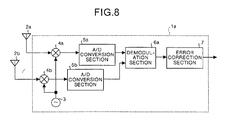
- Fig. 8 is a diagram showing the configuration of a third embodiment of a receiver according to the present invention.
- reference numeral 1a denotes a receiver
- reference numerals 2a, ..., 2b denote P (arbitrary integer) antennas 2a, ..., 2b
- reference numeral 3 denotes a oscillator
- reference numerals 4a, ..., 4b denote P down-convert units
- reference numerals 5a, ..., 5b denote P A/D conversion units
- reference numeral 6a denotes a demodulation unit
- reference numeral 7 denotes an error correction unit.
- the receiver 1a A basic operation of a main part of the receiver 1a will be briefly described below.
- P transmitted signals are received through the P antennas 2a, ..., 2b.
- the down-convert units 4a, ..., 4b down-convert the P signals received on the basis of the frequency generated by the oscillator 3.
- the A/D conversion sections 5a, ..., 5b convert the P down-converted analog signals into digital signals (to be referred to as received signals hereinafter), respectively.
- the demodulation section 6a performs a demodulation process by using the P A/D-converted received signals (the details of the demodulation section 6a which is a characteristic feature of the present invention will be described later) .
- the error correction section 7 performs error correction processes such as a deinterleaving process and a decoding process to the demodulated signals.
- Fig. 9 is a diagram showing the configuration of the demodulation section 6a of the third embodiment.
- reference numerals 21a, ..., 21b denote P frequency offset correction value estimation sections
- reference numerals 22a,.., 22b denote P frequency offset correction sections
- reference numeral 23a denotes an equalizer
- reference numeral 24 denotes a combining unit.
- the configurations and the operations of the frequency offset correction value estimation sections are the same as those of the frequency offset correction value estimation section 21 described above. For this reason, the same reference numerals as in the frequency offset correction value estimation sections denote the same parts in the frequency offset correction value estimation section 21, and a description thereof will be omitted.
- the P frequency offset correction value estimation sections 21a, ..., 21b receive corresponding received signals, respectively, and independently perform the same process as that performed by the frequency offset correction value estimation section 21 of the first embodiment described above to output correction values of frequency offsets.
- the combining section 24 receives the correction values of the P frequency offsets output from the P frequency offset correction value estimation sections 21a to 21b, thereafter, calculates the average of these correction values, and outputs the average value as a correction value of a frequency offset.
- the P frequency offset correction sections 22a to 22b receive corresponding received signals and the average value, independently perform the same process as that of the frequency offset correction section 22 of the first embodiment described above, and perform correction processes of the respective frequency offsets.
- the equalizer 23a receives the P corrected received signals, demodulates the received signals in consideration of distortion caused by a multipath such as frequency selective fading, and outputs the demodulation result to the error correction section 7.
- the equalizer the same equalizer as that used in the first embodiment described above is used.
- the same effect as that in the first embodiment can be achieved according to the third embodiment.
- communication having higher quality can be realized.
- the combining section 24 calculates the sum of estimation values of frequency offsets of P complex numbers, and outputs the sum as an estimation value of a frequency offset of a common complex number.
- the P frequency offset correction sections 22a to 22b receive the corresponding received signals and the sum, and independently performthe processes of Equations (2) and (4) as in the first embodiment described above.
- Fig. 10 is a diagram showing the configuration of a fourth embodiment of a receiver according to the present invention. More specifically, Fig. 10 is a diagram showing the configuration of a demodulation section 6a according to the fourth embodiment.
- reference numeral 51 denotes an averaging section
- reference numerals 52a, ..., 52b denote frequency offset correction sections.
- the other configuration is the same as that in Fig. 9 of the third embodiment described above.
- the same reference numerals as in Fig. 9 denote the same parts in Fig. 10, and a description thereof will be omitted. Subsequently, in this embodiment, only parts which are different from the parts of the third embodiment described above will be described below.
- frequency offset correction values output from the combining section 24 is averaged.
- a received signal is corrected by using Equations (6) and (7) described above on the basis of the common correction value output from the averaging section 51.
- the P frequency offset correction sections 22a, ..., 22b correct received signals for the frequency offset components which cannot be corrected by the frequency offset correction sections 52a, ..., 52b.
- the circuit configuration can be simplified.
- the same diversity effect as that of the third embodiment can be obtained, and estimation values of frequency offsets in a plurality of frames are averaged to make it possible to estimate a frequency offset at a high precision.
- a frequency offset is corrected on the basis of the estimation value, communication having higher quality can be realized.
- an estimation value of a frequency offset to be used is selected depending on communication conditions such as a state of a channel, and distortion depending on a frequency offset in a received signal is corrected on the basis of the selected estimation value of the frequency offset, preferable communication quality can be advantageously achieved even in a communication environment in which intersymbol interference caused by a multipath exists.
- estimation values of frequency offsets in a plurality of frames are averaged, so that a frequency offset can be estimated at a high precision.
- the frequency offset is corrected on the basis of the estimation value, so that more preferable communication quality can be advantageously realized.
- estimation values of frequency offsets in a plurality of frames are averaged, so that a frequency offset can be estimated at a high precision.
- an oscillator is directly controlled on the basis of the estimation value, so that more preferable communication quality can be advantageously realized.
- a configuration in which a frequency offset correction unit is omitted is employed, so that the circuit configuration can be advantageously simplified while communication quality which is preferable more than that of a conventional receiver is realized.
- a configuration which can perform diversity reception is arranged, so that communication having higher quality can be advantageously realized.
- a configuration which can perform diversity reception is arranged, so that communication having higher quality can be advantageously realized.
- a configuration which can perform diversity reception is arranged, so that communication having higher quality can be advantageously realized.
- a configuration in which a frequency offset correction unit is omitted is used, and a configuration which can perform diversity reception is arranged, so that the circuit configuration can be advantageously simplified while communication quality higher than that of a conventional receiver is realized.
- the frequency offset correction unit of subsequent can exactly correct received signal on the basis of collect value of estimation value switching control output, therefore, demodulation accuracy can drastically improve by equalizer.
- any one of an estimation value of a frequency offset of an output from a first frequency offset estimation unit and an estimation value of a frequency offset of an output from a second frequency offset estimation unit is selected.
- the estimation precision of the frequency offset can be considerably improved, the frequency offset can be advantageously corrected at a high precision.
- any one of an estimation value of a frequency offset of an output from a first frequency offset estimation unit and an estimation value of a frequency offset of an output from a second frequency offset estimation unit is selected.
- the frequency offset can be advantageously corrected at a high precision.
- an apparent decision reference (threshold value) can be set from a power of an arrival path, and a more precise amount of delay can be known. For this reason, an estimation value selection unit can easily perform switching control of the estimation value switching unit at a high precision advantageously.
- an apparent decision reference (threshold value) can be set from a noise power, and a more precise amount of delay can be known. For this reason, an estimation value selection unit can easily perform switching control of the estimation value switching unit at a high precision advantageously.
- an apparent decision reference (threshold value) can be set from a power of an arrival path or a noise power, and a more precise amount of delay can be known. For this reason, an estimation value selection unit can easily perform switching control of the estimation value switching unit at a high precision advantageously.
- a wireless communication receiver is useful for a device having a frequency offset correction function, and is suitable for a receiver for wireless communication of an automobile telephone, a portable telephone, a cordless telephone, or the like.
Landscapes
- Engineering & Computer Science (AREA)
- Computer Networks & Wireless Communication (AREA)
- Signal Processing (AREA)
- Digital Transmission Methods That Use Modulated Carrier Waves (AREA)
- Circuits Of Receivers In General (AREA)
- Channel Selection Circuits, Automatic Tuning Circuits (AREA)
- Mobile Radio Communication Systems (AREA)
- Cable Transmission Systems, Equalization Of Radio And Reduction Of Echo (AREA)
Abstract
A frequency offset correction value estimation section
(21) receives a signal including a predetermined fixed
pattern from a transmission side, thereafter, selects a
combination of fixed patterns used in a process of estimating
a frequency offset is selected depending on the state of
a channel, and an estimation result of the frequency offset
calculated by the combination of the fixed patterns is output
as a correction value of a determined frequency offset. A
frequency offset correction section (22) receives the
received signal obtained after the correction is performed
for correcting a frequency offset of the received signal
on the basis of the correction value, and an equalizer (23)
demodulates the received signal by using a predetermined
algorithm.
Description
The present invention relates to a receiver which can
be applied to a wireless communication for example in
automobile telephones, portable telephones, cordless
telephones. Particularly, this invention relates to a
wireless communication receiver having a frequency offset
correction function.
A conventional wireless communication receiver will
be described below. For example, a transmitter generates
a signal which executes channel encoding to information data
including data obtained by encoding voice, data of the
internet, and the like and which transmits the resultant
information data. After the signal is modulated,
up-conversion is executed on the basis of a frequency
generated by a local oscillator. The transmitted signal
obtained here is transmitted through an antenna.
Thereafter, the transmitted signal is received by a
receiver through an antenna, and is down-converted on the
basis of a frequency generated by a local oscillator. The
down-converted received signal is converted into a digital
received signal (to be referred to as a received signal
hereinafter) by an analog/digital converter.
In general, an offset exists between the frequencies
of the oscillator in the transmitter and the oscillator in
the receiver. In this case, the offset of the frequencies,
i.e., the frequency offset causes the received signal to
be distorted. For this reason, in order to realize
communication having high quality, the frequency offset must
be corrected.
In addition, in a communication environment of an
automobile telephone, distortion of the received signal may
be generated by frequency selective fading caused by
intersymbol interference. In such a case, the receiver must
perform a correction process for the frequency offset and
a demodulation process in consideration of the intersymbol
interference.
As a conventional receiver having a frequency offset
correction function, for example, an automatic frequency
control circuit (to be referred to as a conventional receiver
hereinafter) described in Japanese Patent Application
Laid-Open No. 10-163816. In this example, the transmission
device repeatedly transmits the pattern of a fixed PN signal
as a preamble pattern, and the receiver calculates a phase
deviation per symbol on the basis of the component of a PN
signal which is demodulated in a preamble period and which
is obtained one cycle before and the signal component of
a present PN code. A conventional receiver performs
correction of a phase in units of symbols in a data period
on the basis of the phase deviation.
However, in the conventional receiver, correction of
the phases is performed on the basis of the phase deviation
calculated by using the preamble pattern. On the other hand,
for example, when the preamble period is elongated to improve
an estimated precision of the frequency offset, the estimated
precision of the frequency offset is deteriorated. In any
cases, communication quality is deteriorated
disadvantageously.
Therefore, it is an object of the present invention
to provide awireless communication receiver which estimates
a frequency offset at a high precision and corrects the
frequency offset in the communication environment in which
frequency selective fading exists so as to make it possible
to realize preferable communication quality.
A wireless communication receiver according to one
aspect of the present invention comprises: a frequency offset
correction value estimation unit (corresponding to a
frequency offset correction value estimation section 21
according to an embodiment to be described later) which
receives a signal including a predetermined fixed pattern
from a transmission side, thereafter, selects a combination
of fixed patterns used in an estimation process of a frequency
offset depending on the state of a channel, and outputs an
estimation result of the frequency offset calculated by using
the combination of the fixed patterns as a correction value
of a determined frequency offset; a frequency offset
correction unit (corresponding to a frequency offset
correction section 22) which corrects a frequency offset
of a received signal on the basis of the correction value;
and an equalizer (corresponding to an equalizer 23) which
receives the received signal obtained after the correction
is performed and which demodulates the received signal by
using a predetermined algorithm.
The wireless communication receiver further
comprises: an averaging unit (corresponding to an averaging
section 51) which averages calculated correction values
calculated the predetermined number of times by the frequency
offset correction value estimation unit; and a feedback
correction unit (corresponding to a frequency offset
correction section 52) which feeds back the averaging result
to correct a frequency offset of subsequent received signals.
The frequency offset correction unit corrects a frequency
offset component which cannot be corrected by the feedback
correction unit.
The wireless communication receiver further comprises
an averaging unit which averages correction values
calculated the predetermined number of times by the frequency
offset correction value estimation unit. An oscillator on
a reception side is directly controlled on the basis of the
averaging result to correct a frequency offset of subsequent
received signals, and the frequency offset correction unit
correct a frequency offset component which cannot be
corrected by the oscillator.
The wireless communication receiver according to an
another aspect of the next comprises: a frequency offset
correction value estimation unit (corresponding to a
frequency offset correction value estimation section 21)
which receives a signal including a predetermined fixed
pattern from a transmission side, thereafter, selects a
combination of fixed patterns used in an estimation process
of a frequency offset depending on the state of a channel,
and outputs an estimation result of the frequency offset
calculated by using the combination of the fixed patterns
as a correction value of a determined frequency offset; an
averaging unit (corresponding to an averaging section 51)
which averages correction values calculated the
predetermined number of times by the frequency offset
correction value estimation unit; a feedback correction unit
(corresponding to a frequency offset correction section 52)
which feeds back the averaging result to correct a frequency
offset of subsequent received signals; and an equalizer
(corresponding to an equalizer 23) which receives the
received signal obtained after the correction is performed
and which demodulates the received signal by using a
predetermined algorithm.
The wireless communication receiver according to still
another aspect of the invention comprises : a frequency offset
correction value estimation unit (corresponding to
frequency offset correction value estimation sections
21a, ..., 21b) of P (arbitrary number) series which receive
signals including predetermined fixed patterns from a
transmission side, thereafter, select combinations of fixed
patterns used in estimation processes of frequency offsets
depending on the state of a channel, and output estimation
results of the frequency offsets calculated by using the
combinations of the fixed patterns as correction values of
determined frequency offsets; a combining unit
(corresponding to a combining section 24) which averages
the P correction values to output an averaging result as
a correction value of a frequency offset being common to
the respective series; a frequency offset correction unit
(corresponding to frequency offset correction sections
22a, ..., 22b) of P series which correct frequency offsets
of received signals on the basis of the common correction
value; and an equalizer (corresponding to an equalizer 23a)
which receives P received signals obtained after the
correction is performed and which demodulates the received
signals by using a predetermined algorithm.
The wireless communication receiver further
comprises: an averaging unit (corresponding to an averaging
section 51) which averages correction values calculated the
predetermined number of times by the combining unit; and
a feedback correction unit (corresponding to frequency
offset correction sections 52a, ..., 52b) of P series which
feed back the averaging result to correct frequency offset
of subsequent received signals. The frequency offset
correction unit of P series correct frequency offset
components which cannot be corrected by the feedback
correction unit of P series, respectively.
The wireless communication receiver further comprises
an averaging unit which averages correction values
calculated the predetermined number of times by the combining
unit. An oscillator on a reception side is directly
controlled on the basis of the averaging result to correct
a frequency offset of subsequent received signals, and the
frequency offset correction unit of P series correct
frequency offset components which cannot be corrected by
the oscillator, respectively.
The wireless communication receiver according to still
another aspect of the invention comprises : a frequency offset
correction value estimation unit (corresponding to
frequency offset correction value estimation sections
21a, ..., 21b) of P (arbitrary number) series which receive
signals including predetermined fixed patterns from a
transmission side, thereafter, select combinations of fixed
patterns used in estimation processes of frequency offsets
depending on the state of a channel, and output estimation
results of the frequency offsets calculated by using the
combinations of the fixed patterns as correction values of
determined frequency offsets; a combining unit
(corresponding to combining section 24) which averages the
P correction values to output an averaging result as a
correction value of a frequency offset being common to the
respective series; an averaging unit (corresponding to an
averaging section 51) which averages correction values
calculated the predetermined number of times by the combining
unit; a feedback correction unit (corresponding to frequency
offset correction sections 52a, ..., 52b) of P series which
feed back the averaging result to correct frequency offset
of subsequent received signals; and an equalizer
(corresponding to an equalizer 23a) which receives Preceived
signals obtained after the correction is performed and which
demodulates the received signals by using a predetermined
algorithm.
In the wireless communication receiver, the frequency
offset correction value estimation unit comprises: a first
frequency offset estimation unit (corresponding to a first
frequency offset estimation section 31) which estimates a
frequency offset of a received signal by using the same fixed
patterns located at different positions; a second frequency
offset estimation unit (corresponding to a second frequency
offset estimation section 32) which estimates a frequency
offset of a received signal by using the same fixed patterns
which are different from the fixed patterns used in the first
frequency offset estimation unit and located at different
positions; an estimation value selection unit
(corresponding to an estimation scheme selection section
33) which selects any one of the estimation values of the
frequency offsets depending on a state of a channel; and
an estimation value switching unit (corresponding to a
correction value switching section 34) which selects the
outputs of the estimation values on the basis of the selection
result.
In the wireless communication receiver, the estimation
value selection unit comprises: a delay spread estimation
unit (corresponding to a delay spread estimation section
41) which estimates an amount of delay of a channel by using
a fixed pattern; anoise power estimation unit (corresponding
to a noise power estimation section 42) which estimates a
noise power by using a fixed pattern; and an estimation value
decision unit (corresponding to an estimation scheme
decision section 43) which decides the estimation value of
one preferably selected frequency offset on the basis of
the estimation value of the delay spread and the estimation
value of the noise power.
In the wireless communication receiver, the estimation
value selection unit comprises: a delay spread estimation
unit which estimates an amount of delay of a channel by using
a fixed pattern; and an estimation value decision unit which
decides the estimation value of one preferably selected
frequency offset on the basis of the estimation value of
the delay spread.
In the wireless communication receiver, the delay
spread estimation unit estimates powers in units of paths
which arrive, calculates a threshold value on the basis of
the powers of M (M is a natural number) paths including a
path having the maximum power, and sets a range including
a path having a power higher than the threshold value as
an estimation value of a delay spread.
In the wireless communication receiver, the delay
spread estimation unit estimates powers in units of paths
which arrive, calculates a threshold value on the basis of
the noise power, and sets a range including a path having
a power higher than the threshold value as an estimation
value of a delay spread.
In the wireless communication receiver, the delay
spread estimation unit estimates powers in units of paths
which arrive, calculates a threshold value on the basis of
powers of M (M is a natural number) paths including a path
having the maximum power or the noise power, and sets a range
including a path having a power higher than the threshold
value as an estimation value of a delay spread.
Fig. 1 includes diagrams showing the configuration
of a first embodiment of a receiver according to the present
invention and the configuration of a conventional
transmission device; Fig. 2 is a diagram showing an example
of a transmission frame format generated by the transmission
device; Fig. 3 is a diagram showing an example of a
transmission frame format generated by the transmission
device; Fig. 4 is a diagram showing the configuration of
a demodulation unit of the first embodiment; Fig. 5 is a
diagram showing a configuration of an estimation scheme
selection unit; Fig. 6 is a diagram showing a method of
estimating a delay spread in a delay spread estimation unit;
Fig. 7 is a diagram showing the configuration of a
demodulation unit in a second embodiment; Fig. 8 is a diagram
showing the configuration of a third embodiment of a receiver
according to the present invention; Fig. 9 is a diagram
showing the configuration of a demodulation unit of the third
embodiment; and Fig. 10 is a diagram showing a demodulation
unit according to a fourth embodiment.
Embodiments of a wireless communication receiver
according to the present invention will be described below
in detail with reference to the accompanying drawings. The
present invention is not limited to the embodiments.
Fig. 1 is a diagram showing the configuration (see
Fig. 1(a) of a first embodiment of a wireless communication
receiver (to be referred to as a receiver hereinafter)
according to the present invention and the configuration
(see Fig. 1(b)) of a conventional wireless communication
receiver (to be referred to as a transmission device
hereinafter). In Fig. 1(a), reference numeral 1 denotes
a receiver, reference numeral 2 denotes an antenna, reference
numeral 3 denotes an oscillator, reference numeral 4 denotes
a down-convert unit, reference numeral 5 denotes an A/D
conversion unit, reference numeral 6 denotes a demodulation
unit, and reference numeral 7 denotes an error correction
unit. In Fig. 1(b), reference numeral 11 denotes a
transmission device, reference numeral 12 denotes a
transmission data generation unit, reference numeral 13
denotes a modulation unit, reference numeral 14 denotes an
oscillator, reference numeral 15 denotes an up-convert unit,
and reference numeral 16 denotes an antenna.
Basic operations of main parts in the receiver 1 and
a transmission device 11 will be briefly described below.
For example, in the transmission device 11, the transmission
data generation section 12 performs channel encoding to
information data including data obtained by encoding voice,
data of the internet, and the like to generate transmission
data. The modulation unit 13 demodulates transmission data
output from the transmission data generation section 12,
and the up-convert unit 15 up-converts the modulated
transmission data on the basis of a frequency generated by
the oscillator 14 ant transmits the up-converted transmitted
signal through the antenna 16.
On the other hand, in the receiver 1 according to the
present invention, the transmitted signal is received
through the antenna 2, and the down-convert section 4
down-converts the received signal on the basis of a frequency
generated by the oscillator 3. The analog/digital
conversion unit 5 (to be referred to as an A/D conversion
unit 5 hereinafter) converts the down-converted analog
signal into a digital signal (to be referred to as a received
signal hereinafter), and the demodulation section 6
demodulates the A/D-converted received signal (the details
of the demodulation section 6 which is the characteristic
feature of the present invention will be described later).
Finally, the error correction section 7 performs an error
correction process such as a deinterleaving process and a
decoding process to the demodulated signal
Fig. 2 is a diagram showing an example of a transmission
frame format generated by the transmission device 11. For
example, a training signal 201 is a known signal on the
receiver 1 side, and is constituted by a fixed pattern 201a
and a fixed pattern 201c and an arbitrary fixed pattern 201b
interposed between the fixed pattern 201a and the fixed
pattern 201c. On both the sides of the training signal 201,
an information signal 202a and an information signal 202b
are present. On the outside of the information signal 202a
and the information signal 202b, a fixed pattern 203a and
a fixed pattern 203b are present. In this embodiment, the
fixed pattern 201a and the fixed pattern 201c must be equal
to each other, and the fixed pattern 203a and the fixed pattern
203b must be equal to each other. The fixed pattern 201b
may not be arranged.
A concrete example of the transmission frame format
in Fig. 2 will be described below. For example, a
transmission frame format is expressed by:
 In the above-mentioned frame format, XX...XXX represents
the
In the above-mentioned frame format, XX...XXX represents
the information signals 202a and 202b, "000" outside the
information signals represents the fixed patterns 203a and
203b, "0101110" inside the information signals represents
the fixed patterns 201a and 201c, and "11010" at the center
represents the arbitrary fixed pattern 201b.
On the other hand, Fig. 3 is a diagram showing an example
of a transmission frame format which is different from that
in Fig. 2 and generated by the transmission device 11. In
this case, the transmission frame is constituted by a
training signal 301, an information signal 302, and a fixed
pattern 303. For example, the training signal 301 is a known
signal on the receiver 1 side, and is constituted by fixed
patterns 301a and 301c and an arbitrary fixed pattern 301b
interposed between the fixed patterns 301a and 301c. The
training signal 301 must partially include the same pattern
as a fixed pattern 303. When the condition is satisfied,
the arbitrary fixed pattern 301b may not be arranged.
A concrete example of the transmission frame format
shown in Fig. 3 will be described below. For example, the
transmission frame format can be expressed by:
 In the above-mentioned frame format, XX...XXX represents
the
In the above-mentioned frame format, XX...XXX represents
the information signal 302, "000" on the right side of the
information signal 302 represents the fixed pattern 303,
"0101100" on the left side of the information signal 302
represents the fixed pattern 301a and the fixed pattern 301c,
and "01010" between the fixed pattern 301a and the fixed
pattern 301c represents the arbitrary fixed pattern 301b.
The training signal 301 includes "000" which is the same
as the fixed pattern 303.
Subsequently, an operation of the demodulation section
6 of the receiver 1 when the transmission frame format shown
in Fig. 2 is received will be described below in detail.
Fig. 4 is a diagram showing the configuration of the
demodulation section 6 according to the first embodiment.
In Fig. 4, reference numeral 21 denotes a frequency offset
correction value estimation unit, reference numeral 22
denotes a frequency offset correction unit, and reference
numeral 23 denotes an equalizer. In the frequency offset
correction value estimation section 21, reference numeral
31 denotes a first frequency offset estimation section 31,
reference numeral 32 denotes a second frequency offset
estimation section, reference numeral 33 denotes an
estimation scheme selection section, and reference numeral
34 denotes a correction value switching section.
For example, in the first frequency offset estimation
section 31, by using the fixed pattern 201a and the fixed
pattern 201c included in a received signal (see the
transmission frame format in Fig. 2), a frequency offset
is estimated as expressed in Equations (1) and (2):
F1 = Σ [r(N13+i) × CONJG {r (N11+i)}]
f1 = arctan {Im(F1)/Re(F1)}/(N13-N11)
In Equations (1) and (2), reference symbol N11 denotes
time corresponding to the start position of the fixed pattern
201a in a received signal r(n), reference symbol N13 denotes
time corresponding to the start position of the fixed pattern
201c in the received signal r(n), reference symbol
CONJG{r(N11 + i) } denotes a complex conjugation of a complex
number r (N11 + i) , reference symbol Re(F1) denotes the real
part of a complex number F1, reference symbol Im(F1) denotes
an imaginary part of the complex number F1, and reference
symbol arctan{Im(F1)/Re(F1)} denotes an arc tangent of a
real number Im(F1)/Re(F1). Symbol Σ in Equation (1)
represents that the sum total from i = L to i = N1 - 1. At
this time, reference symbol N1 denotes the lengths of the
fixed patterns 201a and 201c, and reference symbol L
represents a length corresponding to the maximum delay time
of an effective delay wave generated in a channel.
In this manner, the value F1 calculated by Equation
(1) represents a result obtained by composing an estimation
value (complex number) of a phase rotation amount generated
in symbols (N13 - N11) by a weight corresponding to the power
of a received signal. The value f1 calculated by Equation
(2) represents an estimation value (angle) of a phase
rotation amount generated in one symbol.
On the other hand, in the second frequency offset
estimation section 32, by using the fixed pattern 203a and
the fixed pattern 203b included in the received signal (see
the transmission frame format in Fig. 2), a frequency offset
is estimated as expressed in Equations (3) and (4).
F3 = r(N32+N3-1)×CONJG {r (N31+N3-1)}
f3 = arctan {Im(F3)/Re(F3)}/(N32-N31)
In Equations (3) and (4), reference symbol N31 denotes
time corresponding to the start position of the fixed pattern
203a in a received signal r(n), reference symbol N32 denotes
time corresponding to the start position of the fixed pattern
203b in the received signal r(n), and reference symbol N3
denotes the lengths of the fixed pattern 203a and 203b.
In this manner, the value F3 calculated by Equation
(3) represents an estimation value (complex number) of a
phase rotation amount generated in symbols (N32 - N31) . The
value f3 calculated by Equation (4) represents an estimation
value (angle) of a phase rotation amount generated in one
symbol.
In the estimation scheme selection section 33, by using
a training signal included in a received signal, any one
of an estimation value of a frequency offset output from
the first frequency offset estimation section 31 and an
estimation value of a frequency offset output from the second
frequency offset estimation section 32 is selected.
In the correction value switching section 34, on the
basis of a selection result obtained by the estimation scheme
selection section 33, an output is switched to any one of
the estimation value of the frequency offset output from
the first frequency offset estimation section 31 and the
estimation value of the frequency offset output from the
second frequency offset estimation section 32. One
estimation value selected here is output to the subsequent
frequency offset correction section 22 as a correction value.
In the frequency offset correction section 22, on the
basis of the correction value output from the correction
value switching section 34, correction of the received signal
is performed by using the following equation:
r'(n) = r(n)×{cos(n×r) - j·sin(n×f)}
In Equation (5), reference symbol j denotes the square
root of (-1), reference symbol r'(n) denotes the corrected
received signal, and reference symbol f denotes a correction
value output from the correction value switching section
34.
Finally, in Fig. 23, the received signal in which
distortion caused by a frequency offset is corrected is
received, and, thereafter, the received signal is
demodulated in consideration of distortion caused by a
multipath caused by frequency selective fading or the like.
The demodulation result is output to the subsequent error
correction section 7. The configuration of the equalizer
23 is not limited to the above configuration.
Maximum-likelihood sequence estimation (MLSE:
Maximum-Likelihood Sequence Estimation) which is a known
technique, decision-feedback sequence estimation (DFSE:
Decision-Feedback Sequence Estimation or DDFSE: Delayed
Decision-Feedback Sequence Estimation), a
decision-feedback equalizer (DFE: Decision-Feedback
Equalizer), RSSE (Reduced-State Sequence Estimation), a
list-output Viterbi equalizer (LVE: List-output Viterbi
Equalizer), an equalizer using an M algorithm, an SOVA
(Soft-Output Viterbi Algorithm), a soft-decision output
equalizer using an algorithm such as MAP (Maximum a
Posteriori), Max-log-MAP, or Log-MAP, an equalizer obtained
by modifying these equalizers, or the like can be used. By
using the configuration including the error correction
section 7, a Turbo Equalizer or an equalizer to which an
error correction function is combined may be used.
A method of selecting the estimation values of the
frequency offsets will be described below. Fig. 5 is a
diagram showing a configuration of the estimation scheme
selection section 33. In Fig. 5, reference numeral denotes
a delay spread estimation section, reference numeral 42
denotes a noise power estimation section, and reference
numeral 43 denotes an estimation scheme decision section.
In the delay spread estimation section 41, by using
a training signal included in a received signal, delay time
of the maximum effective delay wave of a channel is estimated,
and the estimation result is output to the estimation scheme
decision section 43 as delay spread time . On the other hand,
in the noise power estimation section 42, a noise power is
estimated by using the training signal included in the
received signal, and the estimation result is output to the
estimation scheme decision section 43. In the estimation
scheme decision section 43, preferably selected one of the
estimation value of the frequency offset output from the
first frequency offset estimation section 31 and the
estimation value of the frequency offset output from the
second frequency offset estimation section 32 is decided
on the basis of the received noise power estimation value
and the delay spread estimation value.
An operation in the estimation scheme selection
section 33 will be described below under the conditions in
which, for example, the length between the fixed patterns
203a and 203b is given by N3 = 3, the length between the
fixed patterns 201a and 201c is given by N1 = 10, and (N32
- N31) is considerably larger than (N13 - N11).
In this case, with respect to an estimation precision,
the estimation value of the output from the second frequency
offset estimation section 32 can be estimated at a precision
higher than that of the estimation value of the output from
the first frequency offset estimation section 31 because
the second frequency of f set estimation section 32 calculates
the phase rotation amount generated in one symbol from the
phase rotation amount generated in the symbols (N32 - N31).
However, when the delay time of the maximum effective delay
wave of the channel is larger than N3, the estimation
precision of the estimation value of the output from the
second frequency offset estimation section 32 is
deteriorated. The estimation value of the output from the
other first frequency offset estimation section 31 can be
estimated at a precision higher than that of the estimation
value of the output from the second frequency offset
estimation section 32.
In the estimation scheme decision section 43, when
the estimation value of the delay spread is larger than the
length N3 between the fixed patterns 203a and 203b, or when
the estimation value of the noise power is larger than a
specific threshold value, the estimation value of the
frequency offset of the output from the first frequency
offset estimation section 31 is selected. In the other case,
the estimation value of the frequency offset of the output
from the second frequency offset estimation section 32 is
selected.
A method of estimating the delay spread will be
described below. Fig. 6 is a diagram showing a method of
estimating a delay spread in the delay spread estimation
section 41. In Fig. 6, reference numerals 601a, 601b, 601c,
601d, 601e, and 601f denote path powers, respectively, and
reference numeral 602 denotes a threshold value of a power.
In the delay spread estimation section 41, on the basis
of a received signal and a training signal, path powers are
estimated. The path powers 601a to 601f in Fig. 6 represent
estimation results, respectively. The abscissa indicates
time. In this case, the path power 601a is a power of a
path which directly arrives, and the path power 601f is a
power of a path having maximum delay time. In the delay
spread estimation section 41, the sum of the path powers
601a to 601c is calculated, and a value obtained by
multiplying a fixed constant to the sum of powers is set
as the threshold value 602. The range until a path having
a power higher than the threshold value 602 is set as an
amount of delay of the channel. In this manner, an accurate
amount of delay can be known, and an apparent decision
reference can be set in the estimation scheme decision
section 43. For this reason, the estimation scheme
selection section 33 can easily perform switching control
of the correction value switching section 34 at a high
precision.
As another method of estimating a delay spread, for
example, a value obtained by multiplying a fixed constant
to a noise power calculated by the noise power estimation
section 42 is set as the threshold value 602. In this state,
the range until the path having a power higher than the
threshold value can also be set as an amount of delay of
the channel.
As a method of estimating a delay spread different
from the methods described above, for example, the sum of
the path powers 601a to 601c is compared with the noise power
calculated by the noise power estimation section 42, and
a value obtained by multiplying a fixed constant to larger
one of the sum of the powers and the noise power is set as
the threshold value 602. In this state, a range until a
path having a power higher than the threshold value 602 may
be set as the amount of delay of the channel.
As described above, in this embodiment, the estimation
value of a frequency offset to be used is selected depending
on communication conditions such as the state of a channel,
and, on the basis of the estimation value of the selected
frequency offset, a distortion depending on the frequency
offset in the received signal is corrected. Even in a
communication environment in which intersymbol
interference caused by a multipath exists, preferable
communication quality can be realized.
In the first embodiment, calculation corresponding
to Equation (2) and Equation (4) are actually performed by
the frequency offset estimation units, respectively. The
present invention is not limited to the embodiment. For
example, the present invention may also be realized by
replacing the calculation results with a ROM table.
In the first embodiment, both the frequency offset
estimation units are operated as described above. However,
the present invention is not limited to this embodiment.
For example, only one of the first frequency offset
estimation section 31 and the second frequency offset
estimation section 32 which is selected by the estimation
scheme selection section 33 may be operated.
The estimation scheme decision section 43 may decide
an estimation value of a frequency offset to be used on the
basis of only the estimation value of the delay spread. In
contrast to this, the estimation value of the frequency
offset to be used may be decided on the basis of only the
estimation value of the noise power.
In the estimation scheme selection section 33, the
estimation value of the frequency offset may be selected
by not only the state of the channel but also a frequency
band to be used. In general, an amount of frequency offset
is increased in proportion to a frequency band to be used.
For this reason, for example, when a higher frequency band
is used, the estimation value of the frequency offset of
the output from the first frequency offset estimation section
31 is used. When a lower frequency band is used, the
estimation value of the frequency offset of the output from
the second frequency offset estimation section 32 is used.
This is because, when a phase rotation amount generated by
a frequency offset is large, and a phase rotation amount
generated in the symbols (N32 - N31) exceeds π, the frequency
offset cannot be precisely estimated by the second frequency
offset estimation section 32.
In the first embodiment, the frequency offset
correction value estimation section 21 performs the
processes of Equations (1) to (4). However, the present
invention is not limited to the embodiment. For example,
the frequency offset correction value estimation section
21 performs the processes of Equations (1) and (3) to output
an estimation value of a frequency offset of a complex number.
Thereafter, the frequency offset correction section 22 may
be performs the processes of Equations (2) and (4).
Fig. 7 is a diagram showing the configuration of a
second embodiment of a receiver according to the present
invention. More specifically, Fig. 7 is a diagram showing
the configuration of a demodulation section 6 in the second
embodiment. In Fig. 7, reference numeral 51 denotes an
averaging section, and reference numeral 52 denotes a
frequency offset correction section. The other
configuration is the same as that in Fig. 4 of the first
embodiment described above. For this reason, the same
reference numerals as in Fig. 4 denote the same parts in
Fig. 7, and a description thereof will be omitted.
Subsequently, in this embodiment, only parts which are
different from the parts of the first embodiment described
above will be described below.
For example, in the averaging section 51, frequency
offset correction values output from the frequency offset
correction value estimation section 21 is averaged. In the
frequency offset correction section 52, a received signal
is corrected by using the following Equations (6) and (7)
on the basis of the average value output from the averaging
section 51:
f(m) = f(m - 1) + Δf(m - 1)
r'(n)= r(n)×[cos{n×f(m)}-j·sin{n×f(m)}]
In Equations (6) and (7), reference symbol Δf(m)
denotes a frequency offset correction value output from the
averaging section 51 in the mth frame, and f(m) denotes a
frequency offset correction value used for correction of
a received signal by the frequency offset correction section
22 in the mth frame.
In this embodiment, the frequency offset correction
section 22 corrects a received signal for the frequency
offset component which cannot be corrected by the frequency
offset correction section 52. By using a configuration in
which the frequency offset correction section 22 is omitted,
the circuit configuration can be simplified.
As described above, in the second embodiment, the same
effect as that of the first embodiment can be obtained, and
estimation values of frequency offsets in a plurality of
frames are averaged to make it possible to estimate a
frequency offset at a high precision. In addition, when
a frequency offset is corrected on the basis of the estimation
value, more preferable communication quality can be
realized.
In the second embodiment, correction of a frequency
offset is performed by the frequency offset correction
section 52. However, the present invention is not limited
to the embodiment. For example, the frequency of the
oscillator 3 may be directly controlled without arranging
the frequency offset correction section 52.
In the second embodiment, the frequency offset
correction value estimation section 21 performs the
processes of Equations (1) and (3) to output an estimation
value of a frequency offset of a complex number. Thereafter,
the frequency offset correction section 22 or the frequency
offset correction section 52 may perform the processes of
Equations (2) and (4).
Fig. 8 is a diagram showing the configuration of a
third embodiment of a receiver according to the present
invention. In Fig. 8, reference numeral 1a denotes a
receiver, reference numerals 2a, ..., 2b denote P (arbitrary
integer) antennas 2a, ..., 2b, reference numeral 3 denotes
a oscillator, reference numerals 4a, ..., 4b denote P
down-convert units, reference numerals 5a, ..., 5b denote
P A/D conversion units, reference numeral 6a denotes a
demodulation unit, and reference numeral 7 denotes an error
correction unit.
A basic operation of a main part of the receiver 1a
will be briefly described below. In the receiver 1a
according to the present invention, P transmitted signals
are received through the P antennas 2a, ..., 2b. First,
the down-convert units 4a, ..., 4b down-convert the P signals
received on the basis of the frequency generated by the
oscillator 3. The A/D conversion sections 5a, ..., 5b
convert the P down-converted analog signals into digital
signals (to be referred to as received signals hereinafter),
respectively. The demodulation section 6a performs a
demodulation process by using the P A/D-converted received
signals (the details of the demodulation section 6a which
is a characteristic feature of the present invention will
be described later) . Finally, the error correction section
7 performs error correction processes such as a
deinterleaving process and a decoding process to the
demodulated signals.
An operation of the demodulation section 6a in the
receiver 1a will be described below. Fig. 9 is a diagram
showing the configuration of the demodulation section 6a
of the third embodiment. In Fig. 9, reference numerals
21a, ..., 21b denote P frequency offset correction value
estimation sections, reference numerals 22a,.., 22b denote
P frequency offset correction sections, reference numeral
23a denotes an equalizer, and reference numeral 24 denotes
a combining unit. The configurations and the operations
of the frequency offset correction value estimation sections
are the same as those of the frequency offset correction
value estimation section 21 described above. For this
reason, the same reference numerals as in the frequency
offset correction value estimation sections denote the same
parts in the frequency offset correction value estimation
section 21, and a description thereof will be omitted.
The P frequency offset correction value estimation
sections 21a, ..., 21b receive corresponding received
signals, respectively, and independently perform the same
process as that performed by the frequency offset correction
value estimation section 21 of the first embodiment described
above to output correction values of frequency offsets. The
combining section 24 receives the correction values of the
P frequency offsets output from the P frequency offset
correction value estimation sections 21a to 21b, thereafter,
calculates the average of these correction values, and
outputs the average value as a correction value of a frequency
offset.
The P frequency offset correction sections 22a to 22b
receive corresponding received signals and the average value,
independently perform the same process as that of the
frequency offset correction section 22 of the first
embodiment described above, and perform correction
processes of the respective frequency offsets. Finally,
the equalizer 23a receives the P corrected received signals,
demodulates the received signals in consideration of
distortion caused by a multipath such as frequency selective
fading, and outputs the demodulation result to the error
correction section 7. As the equalizer, the same equalizer
as that used in the first embodiment described above is used.
As described above, the same effect as that in the
first embodiment can be achieved according to the third
embodiment. For example, when a configuration which can
achieve diversity reception is used, communication having
higher quality can be realized.
As in the first embodiment described above, when a
configuration in which the P frequency offset correction
value estimation sections 21a to 21b perform only the
processes of Equations (1) and (3) is used, the combining
section 24 calculates the sum of estimation values of
frequency offsets of P complex numbers, and outputs the sum
as an estimation value of a frequency offset of a common
complex number. The P frequency offset correction sections
22a to 22b receive the corresponding received signals and
the sum, and independently performthe processes of Equations
(2) and (4) as in the first embodiment described above.
Fig. 10 is a diagram showing the configuration of a
fourth embodiment of a receiver according to the present
invention. More specifically, Fig. 10 is a diagram showing
the configuration of a demodulation section 6a according
to the fourth embodiment. In Fig. 10, reference numeral
51 denotes an averaging section, and reference numerals
52a, ..., 52b denote frequency offset correction sections.
The other configuration is the same as that in Fig. 9 of
the third embodiment described above. For this reason, the
same reference numerals as in Fig. 9 denote the same parts
in Fig. 10, and a description thereof will be omitted.
Subsequently, in this embodiment, only parts which are
different from the parts of the third embodiment described
above will be described below.
For example, in the averaging section 51, frequency
offset correction values output from the combining section
24 is averaged. In each of the frequency offset correction
sections 52a, ..., 52b, a received signal is corrected by
using Equations (6) and (7) described above on the basis
of the common correction value output from the averaging
section 51.
In the fourth embodiment, the P frequency offset
correction sections 22a, ..., 22b correct received signals
for the frequency offset components which cannot be corrected
by the frequency offset correction sections 52a, ..., 52b.
By using a configuration in which the P frequency offset
correction sections 22a, ..., 22b are omitted, the circuit
configuration can be simplified.
As described above, in the fourth embodiment, the same
diversity effect as that of the third embodiment can be
obtained, and estimation values of frequency offsets in a
plurality of frames are averaged to make it possible to
estimate a frequency offset at a high precision. In addition,
when a frequency offset is corrected on the basis of the
estimation value, communication having higher quality can
be realized.
As described above, according to the present invention,
an estimation value of a frequency offset to be used is
selected depending on communication conditions such as a
state of a channel, and distortion depending on a frequency
offset in a received signal is corrected on the basis of
the selected estimation value of the frequency offset,
preferable communication quality can be advantageously
achieved even in a communication environment in which
intersymbol interference caused by a multipath exists.
According to the next invention, estimation values
of frequency offsets in a plurality of frames are averaged,
so that a frequency offset can be estimated at a high precision.
In addition, the frequency offset is corrected on the basis
of the estimation value, so that more preferable
communication quality can be advantageously realized.
According to the next invention, estimation values
of frequency offsets in a plurality of frames are averaged,
so that a frequency offset can be estimated at a high precision.
In addition, an oscillator is directly controlled on the
basis of the estimation value, so that more preferable
communication quality can be advantageously realized.
According to the next invention, a configuration in
which a frequency offset correction unit is omitted is
employed, so that the circuit configuration can be
advantageously simplified while communication quality
which is preferable more than that of a conventional receiver
is realized.
According to the next invention, in addition to a
configuration which selects an estimation value of a
frequency offset to be used depending on communication
conditions such as the state of a channel and which correct
distortion depending on a frequency offset on the basis of
the selected estimation value of the frequency offset, a
configuration which can perform diversity reception is
arranged, so that communication having higher quality can
be advantageously realized.
According to the next invention, in addition to a
configuration which averages estimation values of frequency
offsets in a plurality of frames to estimate a frequency
offset at a higher precision and corrects the frequency
offset on the basis of the estimation value, a configuration
which can perform diversity reception is arranged, so that
communication having higher quality can be advantageously
realized.
According to the next invention, in addition to a
configuration which averages estimation values of frequency
offsets in a plurality of frames to estimate a frequency
offset at a higher precision and directly control an
oscillator on the basis of the estimation value, a
configuration which can perform diversity reception is
arranged, so that communication having higher quality can
be advantageously realized.
According to the next invention, a configuration in
which a frequency offset correction unit is omitted is used,
and a configuration which can perform diversity reception
is arranged, so that the circuit configuration can be
advantageously simplified while communication quality
higher than that of a conventional receiver is realized.
According to the next invention, the frequency offset
correction unit of subsequent can exactly correct received
signal on the basis of collect value of estimation value
switching control output, therefore, demodulation accuracy
can drastically improve by equalizer.
According to the next invention, for example, on the
basis of a comparison result of an estimation value of a
delay spread and a length between two fixed patterns or a
comparison result of an estimation value of a noise power
and a specific threshold value (power), any one of an
estimation value of a frequency offset of an output from
a first frequency offset estimation unit and an estimation
value of a frequency offset of an output from a second
frequency offset estimation unit is selected. In this
manner, since the estimation precision of the frequency
offset can be considerably improved, the frequency offset
can be advantageously corrected at a high precision.
According to the next invention, for example, on the
basis of a comparison result of an estimation value of a
delay spread and a length between two fixed patterns, any
one of an estimation value of a frequency offset of an output
from a first frequency offset estimation unit and an
estimation value of a frequency offset of an output from
a second frequency offset estimation unit is selected. In
this manner, since the estimation precision of the frequency
offset can be considerably improved, the frequency offset
can be advantageously corrected at a high precision.
According to the next invention, an apparent decision
reference (threshold value) can be set from a power of an
arrival path, and a more precise amount of delay can be known.
For this reason, an estimation value selection unit can
easily perform switching control of the estimation value
switching unit at a high precision advantageously.
According to the next invention, an apparent decision
reference (threshold value) can be set from a noise power,
and a more precise amount of delay can be known. For this
reason, an estimation value selection unit can easily perform
switching control of the estimation value switching unit
at a high precision advantageously.
According to the next invention, an apparent decision
reference (threshold value) can be set from a power of an
arrival path or a noise power, and a more precise amount
of delay can be known. For this reason, an estimation value
selection unit can easily perform switching control of the
estimation value switching unit at a high precision
advantageously.
As described above, a wireless communication receiver
according to the present invention is useful for a device
having a frequency offset correction function, and is
suitable for a receiver for wireless communication of an
automobile telephone, a portable telephone, a cordless
telephone, or the like.
Claims (14)
- A wireless communication receiver comprising:a frequency offset correction value estimation unit which receives a signal including a predetermined fixed pattern from a transmission side, thereafter, selects a combination of fixed patterns used in an estimation process of a frequency offset depending on the state of a channel, and outputs an estimation result of the frequency offset calculated by using the combination of the fixed patterns as a correction value of a determined frequency offset;a frequency offset correction unit which corrects a frequency offset of a received signal on the basis of the correction value; andan equalizing unit which receives the received signal obtained after the correction is performed and which demodulates the received signal by using a predetermined algorithm.
- The wireless communication receiver according to claim 1, further comprising:wherein the frequency offset correction unit corrects a frequency offset component which cannot be corrected by the feedback correction unit.an averaging unit which averages calculated correction values calculated the predetermined number of times by the frequency offset correction value estimation unit; anda feedback correction unit which feeds back the averaging result to correct a frequency offset of subsequent received signals,
- The wireless communication receiver according to claim 1, further comprising:wherein an oscillator on a reception side is directly controlled on the basis of the averaging result to correct a frequency offset of subsequent received signals, andan averaging unit which averages correction values calculated the predetermined number of times by the frequency offset correction value estimation unit,
the frequency offset correction unit correct a frequency offset component which cannot be corrected by the oscillator. - A wireless communication receiver comprising:a frequency offset correction value estimation unit which receives a signal including a predetermined fixed pattern from a transmission side, thereafter, selects a combination of fixed patterns used in an estimation process of a frequency offset depending on the state of a channel, and outputs an estimation result of the frequency offset calculated by using the combination of the fixed patterns as a correction value of a determined frequency offset;an averaging unit which averages correction values calculated the predetermined number of times by the frequency offset correction value estimation unit;a feedback correction unit which feeds back the averaging result to correct a frequency offset of subsequent received signals; andan equalizing unit which receives the received signal obtained after the correction is performed and which demodulates the received signal by using a predetermined algorithm.
- A wireless communication receiver comprising:a frequency offset correction value estimation unit of P (arbitrary number) series which receive signals including predetermined fixed patterns from a transmission side, thereafter, select combinations of fixed patterns used in estimation processes of frequency offsets depending on the state of a channel, and output estimation results of the frequency offsets calculated by using the combinations of the fixed patterns as correction values of determined frequency offsets;a combining unit which averages the P correction values to output an averaging result as a correction value of a frequency offset being common to the respective series;a frequency offset correction unit of P series which correct frequency offsets of received signals on the basis of the common correction value; andan equalizing unit which receives P received signals obtained after the correction is performed and which demodulates the received signals by using a predetermined algorithm.
- The wireless communication receiver according to claim 5, further comprising:wherein the frequency offset correction unit of P series correct frequency offset components which cannot be corrected by the feedback correction unit of P series, respectively.an averaging unit which averages correction values calculated the predetermined number of times by the combining unit; anda feedback correction unit of P series which feed back the averaging result to correct frequency offset of subsequent received signals,
- The wireless communication receiver according to claim 5, further comprising:wherein an oscillator on a reception side is directly controlled on the basis of the averaging result to correct a frequency offset of subsequent received signals, andan averaging unit which averages correction values calculated the predetermined number of times by the combining unit,
the frequency offset correction unit of P series correct frequency offset components which cannot be corrected by the oscillator, respectively. - A wireless communication receiver comprising:a frequency offset correction value estimation unit of P (arbitrary number) series which receive signals including predetermined fixed patterns from a transmission side, thereafter, select combinations of fixed patterns used in estimation processes of frequency offsets depending on the state of a channel, and output estimation results of the frequency offsets calculated by using the combinations of the fixed patterns as correction values of determined frequency offsets;a combining unit which averages the P correction values to output an averaging result as a correction value of a frequency offset being common to the respective series;an averaging unit which averages correction values calculated the predetermined number of times by the combining unit;a feedback correction unit of P series which feed back the averaging result to correct frequency offset of subsequent received signals; andan equalizing unit which receives P received signals obtained after the correction is performed and which demodulates the received signals by using a predetermined algorithm.
- The wireless communication receiver according to claim 1, wherein the frequency offset correction value estimation unit includes,
a first frequency offset estimation unit which estimates a frequency offset of a received signal by using the same fixed patterns located at different positions;
a second frequency offset estimation unit which estimates a frequency offset of a received signal by using the same fixed patterns which are different from the fixed patterns used in the first frequency offset estimation unit and located at different positions;
an estimation value selection unit which selects any one of the estimation values of the frequency offsets depending on a state of a channel; and
an estimation value switching unit which selects the outputs of the estimation values on the basis of the selection result. - The wireless communication receiver according to claim 9, wherein the estimation value selection unit includes,
a delay spread estimation unit which estimates an amount of delay of a channel by using a fixed pattern;
a noise power estimation unit which estimates a noise power by using a fixed pattern; and
a estimation value decision unit which decides the estimation value of one preferably selected frequency offset on the basis of the estimation value of the delay spread and the estimation value of the noise power. - The wireless communication receiver according to claim 9, wherein the estimation value selection unit includes,
a delay spread estimation unit which estimates an amount of delay of a channel by using a fixed pattern; and
an estimation value decision unit which decides the estimation value of one preferably selected frequency offset on the basis of the estimation value of the delay spread. - The wireless communication receiver according to claim 10, wherein the delay spread estimation unit estimates powers in units of paths which arrive, calculates a threshold value on the basis of the powers of M (M is a natural number) paths including a path having the maximum power, and sets a range including a path having a power higher than the threshold value as an estimation value of a delay spread.
- The wireless communication receiver according to claim 10, wherein the delay spread estimation unit estimates powers in units of paths which arrive, calculates a threshold value on the basis of the noise power, and sets a range including a path having a power higher than the threshold value as an estimation value of a delay spread.
- The wireless communication receiver according to claim 10, wherein the delay spread estimation unit estimates powers in units of paths which arrive, calculates a threshold value on the basis of powers of M (M is a natural number) paths including a path having the maximum power or the noise power, and sets a range including a path having a power higher than the threshold value as an estimation value of a delay spread.
Applications Claiming Priority (3)
| Application Number | Priority Date | Filing Date | Title |
|---|---|---|---|
| JP2000231065 | 2000-07-31 | ||
| JP2000231065A JP3866908B2 (en) | 2000-07-31 | 2000-07-31 | Wireless communication receiver |
| PCT/JP2001/002260 WO2002011381A1 (en) | 2000-07-31 | 2001-03-22 | Radio communication receiver |
Publications (2)
| Publication Number | Publication Date |
|---|---|
| EP1225739A1 true EP1225739A1 (en) | 2002-07-24 |
| EP1225739A4 EP1225739A4 (en) | 2009-03-25 |
Family
ID=18723942
Family Applications (1)
| Application Number | Title | Priority Date | Filing Date |
|---|---|---|---|
| EP01915682A Withdrawn EP1225739A4 (en) | 2000-07-31 | 2001-03-22 | RADIO COMMUNICATION RECEIVER |
Country Status (5)
| Country | Link |
|---|---|
| US (1) | US6952570B2 (en) |
| EP (1) | EP1225739A4 (en) |
| JP (1) | JP3866908B2 (en) |
| CN (1) | CN1149799C (en) |
| WO (1) | WO2002011381A1 (en) |
Cited By (1)
| Publication number | Priority date | Publication date | Assignee | Title |
|---|---|---|---|---|
| WO2007148267A1 (en) * | 2006-06-20 | 2007-12-27 | Nxp B.V. | Method and apparatus for estimating carrier frequency offset |
Families Citing this family (27)
| Publication number | Priority date | Publication date | Assignee | Title |
|---|---|---|---|---|
| GB0124952D0 (en) * | 2001-10-17 | 2001-12-05 | Nokia Corp | A receiver and a receiving method |
| US7333573B2 (en) | 2002-08-23 | 2008-02-19 | Hitachi Kokusai Electric Inc. | Radio communication apparatus and method having automatic frequency control function |
| US20040087277A1 (en) * | 2002-10-31 | 2004-05-06 | Siemens Information And Communication Mobile Llc. | Method and apparatus for improving accuracy of radio timing measurements |
| US7359711B2 (en) * | 2002-10-31 | 2008-04-15 | Siemens Communications, Inc. | Methods and apparatus for improving accuracy of radio timing measurements |
| US6882694B2 (en) * | 2002-12-31 | 2005-04-19 | Nokia Corporation | Apparatus, and associated method, for estimating frequency offset of a data symbol communicated in a communication system |
| US7177609B1 (en) * | 2003-05-16 | 2007-02-13 | National Semiconductor Corporation | Chopper-direct-conversion (CDC) radio architecture |
| JP4346465B2 (en) * | 2003-09-29 | 2009-10-21 | 三洋電機株式会社 | Receiving method and apparatus |
| CN1754363A (en) * | 2004-04-28 | 2006-03-29 | 三菱电机株式会社 | Automatic frequency control circuit and automatic frequency control method |
| DE102004052898B4 (en) * | 2004-11-02 | 2009-10-29 | Infineon Technologies Ag | Compensation of the carrier frequency offset in a designed for several types of modulation receiving device of a mobile communication system |
| JP4338624B2 (en) * | 2004-12-07 | 2009-10-07 | 三洋電機株式会社 | Frequency offset estimation method and frequency offset correction apparatus using the same |
| DE602005010574D1 (en) * | 2005-08-12 | 2008-12-04 | St Microelectronics Belgium Nv | Receiver with two-stage compensation of the frequency shift for an M-stage phase-modulated signal |
| US7768439B2 (en) * | 2005-09-07 | 2010-08-03 | Nec Corporation | Data transmission system |
| US8155600B2 (en) * | 2007-12-03 | 2012-04-10 | Texas Instruments Incorporated | Digital communication using an inexpensive reference crystal |
| US8738486B2 (en) * | 2007-12-31 | 2014-05-27 | Mastercard International Incorporated | Methods and apparatus for implementing an ensemble merchant prediction system |
| US20100279643A1 (en) * | 2008-01-21 | 2010-11-04 | Yasushi Maruta | Communication device, communication system, control method, and control program |
| KR101278031B1 (en) * | 2008-12-22 | 2013-06-21 | 한국전자통신연구원 | Parallel automatic frequency offset estimation apparatus and method |
| JP5159673B2 (en) * | 2009-03-09 | 2013-03-06 | 三菱電機株式会社 | Modulation method estimation device |
| US8265184B2 (en) | 2009-11-18 | 2012-09-11 | Wi-Lan, Inc. | Digital communications receiver and method of estimating residual carrier frequency offset in a received signal |
| US8437432B2 (en) * | 2010-03-22 | 2013-05-07 | DecaWave, Ltd. | Receiver for use in an ultra-wideband communication system |
| US8682251B2 (en) * | 2011-03-21 | 2014-03-25 | Telefonaktiebolaget L M Ericsson (Publ) | Apparatus and methods for estimation of a subchannel power imbalance ratio (SCPIR) |
| US8723553B1 (en) * | 2013-02-22 | 2014-05-13 | Qualcomm Incorporated | Systems and methods for performing frequency offset estimation |
| US9154337B2 (en) * | 2013-03-15 | 2015-10-06 | Acorn Technologies, Inc. | Non-linear time domain channel estimation in OFDM systems |
| US9629110B2 (en) * | 2013-04-03 | 2017-04-18 | Keysight Technologies Singapore (Holdings) Pte. Ltd. | Wireless communication apparatus and method performing signal scanning to determine the strongest signal useable for stabilizing a local oscillator |
| US10521866B2 (en) | 2013-10-15 | 2019-12-31 | Mastercard International Incorporated | Systems and methods for associating related merchants |
| CN104808039B (en) * | 2015-04-28 | 2018-08-28 | 深圳市共进电子股份有限公司 | The automatic correction system and method for a kind of electronic equipment |
| DE102017207604B4 (en) * | 2017-05-05 | 2019-11-28 | Conti Temic Microelectronic Gmbh | Radar system with frequency modulation monitoring of a series of similar transmission signals |
| US11777763B2 (en) * | 2020-03-20 | 2023-10-03 | Nantworks, LLC | Selecting a signal phase in a communication system |
Family Cites Families (11)
| Publication number | Priority date | Publication date | Assignee | Title |
|---|---|---|---|---|
| JPH07123125A (en) * | 1993-10-21 | 1995-05-12 | Kokusai Electric Co Ltd | Automatic frequency control circuit |
| FI96257C (en) * | 1994-04-13 | 1996-05-27 | Nokia Telecommunications Oy | A method for determining the phase error of a radio frequency signal, as well as a receiver |
| JP3404436B2 (en) * | 1994-11-16 | 2003-05-06 | 株式会社日立国際電気 | Automatic frequency control method of modulated wave signal |
| JP3467888B2 (en) * | 1995-02-08 | 2003-11-17 | 三菱電機株式会社 | Receiving device and transmitting / receiving device |
| JP3789157B2 (en) * | 1996-03-05 | 2006-06-21 | 三菱電機株式会社 | Frequency error estimation device |
| JP2959498B2 (en) | 1996-11-27 | 1999-10-06 | 日本電気株式会社 | Automatic frequency control circuit |
| IL120210A (en) * | 1997-02-13 | 1999-12-31 | Dspc Tech Ltd | Synchronization system and method for digital communication systems |
| AU723679B2 (en) * | 1997-03-04 | 2000-08-31 | Mitsubishi Denki Kabushiki Kaisha | Receiver with a frequency offset correcting function |
| US6058150A (en) * | 1997-09-30 | 2000-05-02 | Wireless Access, Inc. | Method and apparatus for combined timing recovery, frame synchronization and frequency offset correction in a receiver |
| JP3683733B2 (en) * | 1999-02-19 | 2005-08-17 | 三菱電機株式会社 | CDMA receiver |
| JP3859903B2 (en) * | 1999-06-10 | 2006-12-20 | 三菱電機株式会社 | Frequency error estimation apparatus and method |
-
2000
- 2000-07-31 JP JP2000231065A patent/JP3866908B2/en not_active Expired - Fee Related
-
2001
- 2001-03-22 WO PCT/JP2001/002260 patent/WO2002011381A1/en not_active Ceased
- 2001-03-22 US US10/069,984 patent/US6952570B2/en not_active Expired - Fee Related
- 2001-03-22 EP EP01915682A patent/EP1225739A4/en not_active Withdrawn
- 2001-03-22 CN CNB018022383A patent/CN1149799C/en not_active Expired - Fee Related
Cited By (2)
| Publication number | Priority date | Publication date | Assignee | Title |
|---|---|---|---|---|
| WO2007148267A1 (en) * | 2006-06-20 | 2007-12-27 | Nxp B.V. | Method and apparatus for estimating carrier frequency offset |
| US8446938B2 (en) | 2006-06-20 | 2013-05-21 | Nxp B.V. | Method and apparatus for estimating carrier frequency offset |
Also Published As
| Publication number | Publication date |
|---|---|
| JP2002044176A (en) | 2002-02-08 |
| US20020123311A1 (en) | 2002-09-05 |
| EP1225739A4 (en) | 2009-03-25 |
| WO2002011381A1 (en) | 2002-02-07 |
| CN1149799C (en) | 2004-05-12 |
| JP3866908B2 (en) | 2007-01-10 |
| CN1386352A (en) | 2002-12-18 |
| US6952570B2 (en) | 2005-10-04 |
Similar Documents
| Publication | Publication Date | Title |
|---|---|---|
| EP1225739A1 (en) | Radio communication receiver | |
| CN101019354B (en) | Multiple Antenna Processing for Transmits for Wireless Local Area Networks | |
| US8938040B2 (en) | Improving receiver performance in a communication network | |
| US8656243B2 (en) | Radio receiver and method for channel estimation | |
| US20090098828A1 (en) | Communications system using adaptive filter that is selected based on output power | |
| US7864835B2 (en) | Communications system using adaptive filter and variable delay before adaptive filter taps | |
| EP1254540A1 (en) | Methods and systems for decoding symbols by combining matched-filtered samples with hard symbol decisions | |
| US6668030B2 (en) | Radio communication systems | |
| US7123667B2 (en) | Receiver for wireless communication | |
| EP1067709A1 (en) | Adaptive equalizer and adaptive equalizing method | |
| EP2432180B1 (en) | Mobile wireless communications device and receiver with demodulation and related methods | |
| US7346129B2 (en) | Payload based channel estimation of a wireless channel | |
| US8184675B2 (en) | Residual frequency offset exploitation | |
| IL194600A (en) | Communications system using adaptive filter and selected adaptive filter taps | |
| US5155744A (en) | Combiner for radio receiving system which uses a viterbi demodulator | |
| JP3875333B2 (en) | Wireless receiver | |
| EP2048837A2 (en) | Communications system using adaptive filter with normalization circuit | |
| EP3349361B1 (en) | A method for the exploitation of image interference in multi-carrier wireless systems | |
| KR101405316B1 (en) | Method for beam forming between fixed station using OFDM | |
| Murata et al. | Joint frequency offset and delay profile estimation technique for nonlinear co-channel interference canceller | |
| JPH06350467A (en) | Receiver for digital communications | |
| JP2005252427A (en) | Wireless communication apparatus and signal receiving circuit |
Legal Events
| Date | Code | Title | Description |
|---|---|---|---|
| PUAI | Public reference made under article 153(3) epc to a published international application that has entered the european phase |
Free format text: ORIGINAL CODE: 0009012 |
|
| 17P | Request for examination filed |
Effective date: 20020222 |
|
| AK | Designated contracting states |
Kind code of ref document: A1 Designated state(s): AT BE CH CY DE DK ES FI FR GB GR IE IT LI LU MC NL PT SE TR |
|
| RBV | Designated contracting states (corrected) |
Designated state(s): DE FR GB |
|
| RAP1 | Party data changed (applicant data changed or rights of an application transferred) |
Owner name: MITSUBISHI DENKI KABUSHIKI KAISHA |
|
| STAA | Information on the status of an ep patent application or granted ep patent |
Free format text: STATUS: THE APPLICATION HAS BEEN WITHDRAWN |
|
| A4 | Supplementary search report drawn up and despatched |
Effective date: 20090223 |
|
| 18W | Application withdrawn |
Effective date: 20090316 |