EP1225685A2 - Drive circuit and method for driving a switched reluctance machine - Google Patents
Drive circuit and method for driving a switched reluctance machine Download PDFInfo
- Publication number
- EP1225685A2 EP1225685A2 EP01204975A EP01204975A EP1225685A2 EP 1225685 A2 EP1225685 A2 EP 1225685A2 EP 01204975 A EP01204975 A EP 01204975A EP 01204975 A EP01204975 A EP 01204975A EP 1225685 A2 EP1225685 A2 EP 1225685A2
- Authority
- EP
- European Patent Office
- Prior art keywords
- winding
- links
- terminal
- windings
- circuit
- Prior art date
- Legal status (The legal status is an assumption and is not a legal conclusion. Google has not performed a legal analysis and makes no representation as to the accuracy of the status listed.)
- Withdrawn
Links
Images


Classifications
-
- H—ELECTRICITY
- H02—GENERATION; CONVERSION OR DISTRIBUTION OF ELECTRIC POWER
- H02P—CONTROL OR REGULATION OF ELECTRIC MOTORS, ELECTRIC GENERATORS OR DYNAMO-ELECTRIC CONVERTERS; CONTROLLING TRANSFORMERS, REACTORS OR CHOKE COILS
- H02P25/00—Arrangements or methods for the control of AC motors characterised by the kind of AC motor or by structural details
- H02P25/02—Arrangements or methods for the control of AC motors characterised by the kind of AC motor or by structural details characterised by the kind of motor
- H02P25/08—Reluctance motors
Definitions
- the present invention is generally related to drive circuits for electromechanical machines, and, more particularly, the present invention is related to an improved drive circuit topology that uses a split winding for driving a switched reluctance machine.
- FIG. 1 shows a standard drive circuit topology 10 generally used to drive a switched reluctance machine and referred in the art as asymmetric bridge.
- FIG. 1 shows the drive circuit topology as applied to a single phase of a polyphase switched reluctance machine and, as shown in FIG. 1, such circuit topology includes two power switches and two power diodes per motor phase.
- power is supplied to a motor phase winding 12 from a direct current (DC) source, such as a battery (not shown).
- a capacitor 11 is connected across first and second supply links 14 and 16. Winding 12 is connected across links 14 and 16 by upper and lower switches 17 and 18.
- Diodes 20 and 22 generally referred to in the art as "free-wheeling" diodes, circulate inductive current in the phase winding when one or both of the respective switches are turned off.
- phase winding 12 is energized by turning on switches 17 and 18.
- Current in the phase winding may be regulated, based on a suitable regulation technique, such as pulse-width-modulation (PWM), by sending the PWM signals to either of switches 17 and 18 to set one of such switches in a non-conductive state while the other switch is set either in conductive or non-conductive state. This is called soft chopping.
- Winding current during off periods of the PWM may be re-circulated through the conductive switch and one of the free-wheeling diodes 20 or 22. This is called zero voltage loop.
- both free-wheeling diodes 20 and 22 may conduct to return winding current to the DC source.
- drive circuit 10 One issue with drive circuit 10 is that if higher power is required for a given machine, the power rating of each silicon-based power device needs to be increased proportionally. This may force the designer to use higher-power-rated devices to account for worst-case scenarios and generally results in higher costs. In view of the foregoing, it would be desirable to provide an improved drive circuit topology that is able to boost torque for a motoring mode or generated current for a generating mode without increase of the power rating of the power devices. This would result in more efficient use of the silicon-based devices, and would lower costs of the drive circuit.
- the present invention fulfills the foregoing needs by providing in one aspect thereof a drive circuit for a switched reluctance machine having at least two windings per pole.
- the circuit includes first and second direct current links.
- the circuit further includes a first winding having first and second terminals. The first winding is connectable across said first and second links.
- a first switch is coupled across the first link and the first terminal of the first winding.
- a second switch is coupled across the second terminal of the first winding and the second link.
- a second winding is connectable in series circuit to that first winding.
- the second winding has first and second terminals.
- a third switch is coupled across one of the first and second links and the second terminal of the second winding.
- Each of the switches is responsive to a respective gating signal to selectively energize and deenergize one of the windings when the machine operates in a first mode of operation and to selectively energize and deenergize both of said windings when the machine operates in a second mode of operation.
- the present invention further fulfills the foregoing needs by providing a method for driving a switched reluctance machine having at least two windings per pole.
- the method allows for providing first and second direct current links.
- the method further allows for providing a first winding having first and second terminals. The first winding is connectable across said first and second links.
- a first switch is coupled across the first link and the first terminal of said first winding.
- a second switch is coupled across the second terminal of said first winding and the second link.
- the method further allows for providing a second winding connectable in series circuit to the first winding.
- the second winding has first and second terminals.
- a third switch is coupled across one of the first and second links and the second terminal of said second winding.
- Each of the switches is responsive to a respective gating signal to selectively energize and deenergize one of the windings when the machine operates in a first mode of operation and to selectively energize and deenergize both windings when the machine operates in a second mode of operation.
- the present invention in one aspect thereof proposes an improved topology for the drive circuit of a switched reluctance machine (SRM).
- SRM switched reluctance machine
- FIG. 2 One exemplary embodiment of the improved drive circuit 100 is illustrated in Fig. 2 where, for the sake of simplicity of illustration, only one phase is shown.
- a capacitor 102 is connected across first and second supply links 104 and 106.
- first link 104 may comprise a positive polarity link
- second link 106 may comprises a negative polarity link.
- the winding of each pole comprises a first winding N1 having first and second terminals 108 and 110 connectable across links 104 and 106 by first and second switches Q1 and Q2.
- first switch Q1 is coupled across first link 104 and the first terminal 108 of first winding N1
- second switch Q2 is coupled across second link 106 and the second terminal 110 of first winding N1.
- the winding of each pole further comprises a second winding N2 connectable in series circuit to first winding N1.
- the second winding includes first and second terminal 112 and 114.
- the number of turns of winding N1 is greater than or equal that the number of turns of winding N2.
- a third switch Q3 is coupled across one of the first and second links, e.g., link 106, and the second terminal 114 of winding N2.
- each of switches Q1-Q3 is responsive to a respective gating signal to energize and deenergize one of such windings (e.g., winding N1) when the machine is in a first mode of operation and to selectively energize and deenergize both of windings N1 and N2 when the machine is in a second mode of operation.
- the first mode of operation may correspond to a relatively high speed operation wherein winding N1 is energized.
- the second mode of operation may correspond to a relatively low speed operation wherein windings N1 and N2 are excited in series.
- Drive circuit 100 further includes a first diode D1 coupled across one of the supply links and the second terminal 114 of the second winding N2.
- first diode D1 has its cathode terminal coupled to link 104 and further has its anode terminal coupled to the second terminal 114 of winding N2.
- a second diode D2 is coupled across one of the terminals of the first winding and one of the supply links.
- second diode D2 has its anode terminal coupled to link 106 and further has its cathode terminal coupled to the first terminal 108 of winding N1.
- a third diode D3 is optionally coupled across one of the supply links and the first terminal of the second winding N2.
- third diode D3 has its anode coupled to the first terminal 112 of winding N2 and has its cathode terminal coupled to link 104.
- the optional diode D3 may be used in case that the mutual electromagnetic coupling between windings N1 and N2 were less than a desired substantially high level for such electromagnetic coupling.
- FIG. 3 shows an exemplary plot of torque and speed plots during motoring
- FIG. 4 shows an exemplary plot of Link or DC current and speed during power generation for the improved topology of the present invention.
- the dashed line represents the characteristic of the machine when only first winding N1 is energized.
- the dotted line represents machine characteristics results when first and second windings N1 and N2 are both excited in series.
- the exemplary plots of FIGS. 3 and 4 correspond to a case where the number of turns of winding N1 is equal to the number of turns of winding N2. It will be appreciated, however, that the present invention is not limited to any particular arrangement regarding the number of turns of either of the windings relative to the number of turns of the other winding.
- the drive circuit of the present invention is switchable between the characteristics shown in FIGS. 3 and 4.
- the overall machine characteristic results in the solid line shown in FIGS. 3 and 4.
- the area represented by the left-tilted pattern represents the boost in torque and generated current achieved by the drive circuit of the present invention at low speed.
- the area represented by right-tilted pattern represents the boost in torque and generated current enabled by the drive circuit of the present invention at high speed, such as may occur when operating in the field-weakening region.
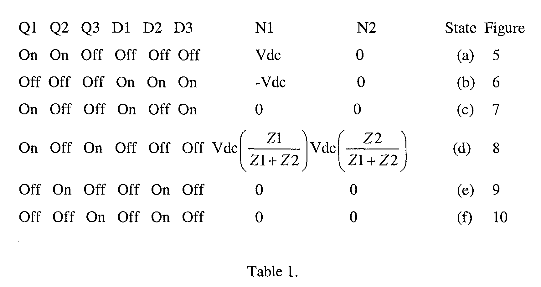
- FIGS. 5- 10 illustrates current flow during various exemplary states of drive circuit 100 that correspond to respective component conditions listed in the following table:
- FIG. 5 energization of first winding N1 corresponds to state (a).
- energization of first and second windings N1 and N2 corresponds to state (d).
- FIGS. 6, 7 ,9, and 10 respectively correspond to states (b), (c), (e) and (f) wherein circulation of inductive current is provided by free-wheeling diodes D1-D3.
- "soft chopping” corresponds to respective states (c), (e), and (f) and "hard chopping” corresponds to state (b).
- hard-chopping refers to the use of positive and negative voltages to regulate the current in a winding.
- the positive voltage is applied when the switch connected to the positive rail and the switch connected to the negative rail are both turned on in order to energize that winding.
- the negative voltage is applied when both these switches are turned off in order to de-energize that winding.
- the inductive current freewheels through both the diode connected to the positive rail, and the diode connected to the negative rail.
- soft chopping refers to the use of zero voltage, and positive and negative voltages to regulate the current in a winding.
- the positive voltage and negative voltages are obtained in the same way as described above in the context of hard chopping.
- the zero voltage is applied when only one switch is turned on, and at least one diode is conducting.
- the inductive current freewheels through one switch and at least one diode.
- FIG. 11 illustrates a block diagram representation of an exemplary power conversion system 200 that embodies one aspect of the present invention.
- a summer 202 receives signal i_ref indicative of a current command.
- Summer 202 further receives a feedback signal i_fbk, such as may be measured by a current sensor 204.
- the output signal from summer 202 is supplied to a current controller 206 that also receives a signal indicative of rotor speed ⁇ from a differentiator 208.
- rotor speed may be determined by mathematically differentiating a signal ⁇ indicative of rotor position of a switched reluctance machine 210.
- Current controller 206 is configured to generate the gating signals respectively applied to switches Q1-Q3 to set drive circuit 100 in a respective one of the states illustrated in FIGS. 5-10.
- the gating signals are generated based on the following parameters: rotor speed, the level of current that actually flows through the split windings relative to the current command signal, and the chopping mode being executed, that is, whether hard chopping or soft chopping is being executed.
- FIG. 12 illustrates another exemplary embodiment for the improved drive circuit of the present invention.
- first diode D1 has its anode terminal coupled to link 106 and further has its cathode terminal coupled to the second terminal 114 of winding N2.
- second diode D2 has its anode terminal coupled to second terminal 110 of winding N1 and has its cathode terminal coupled to link 104.
- Optional third diode D3 has its anode coupled to link 106 and has its cathode terminal coupled to the first terminal 112 of winding N2.
- the prior art device of FIG. 1 can only provide the torque/current characteristics represented by either the dashed line or the dotted line in FIGS. 3 and 4, but not both.
- the incremental boost depicted by the dotted line in FIGS. 3 and 4 would require to double the ratings of the silicon-based devices used in such prior art architecture, assuming a case where windings N1 and N2 have the same number of turns.
- the topology of the present invention one can obtain the incremental boost in the low-speed region of operation, that is, below switching point ⁇ c , by adding one controllable switch and, optionally adding, one diode without having to change the ratings of any of the devices used to drive a given machine. Consequently, due to the use of less silicon, it is believed that the present invention would advantageously result in lower costs.
- the present invention can be embodied in the form of microprocessor-implemented processes and apparatus for practicing those processes.
- the present invention can also be embodied in the form of microprocessor program code containing microprocessor-readable instructions embodied in tangible media, such as floppy diskettes, CD-ROMs, hard drives, or any other computer-readable storage medium, wherein, when the microprocessor program code is loaded into and executed by a microprocessor, the microprocessor becomes an apparatus for practicing the invention.
- the microprocessor program code segments configure the microprocessor to create specific logic circuits or processing modules.
Landscapes
- Engineering & Computer Science (AREA)
- Power Engineering (AREA)
- Control Of Electric Motors In General (AREA)
Abstract
Description
Claims (21)
- A drive circuit (e.g., 100) for a switched reluctance machine having at least two windings per pole, said circuit comprising:first and second direct current links (104 and 106);a first winding (e.g., N1) having first and second terminals (108 and 110), said first winding connectable across said first and second links;a first switch (e.g., Q1) coupled across the first link and the first terminal of said first winding;a second switch (e.g., Q2) coupled across the second terminal of said first winding and the second link;a second winding (e.g., N2) connectable in series circuit to said first winding, said second winding having first and second terminals (112 and 114);a third switch (e.g., Q3) coupled across one of the first and second links and the second terminal of said second winding, wherein each of said switches is responsive to a respective gating signal to selectively energize and deenergize one of said windings when the machine operates in a first mode of operation and to selectively energize and deenergize both of said windings when the machine operates in a second mode of operation.
- The circuit of claim 1 further comprising a first diode (e.g., D1) coupled across one of the first and second links and the second terminal of the second winding.
- The circuit of claim 2 further comprising a second diode (e.g., D2) coupled across one of the terminals of the first winding and one of the first and second links.
- The circuit of claim 3 further comprising a third diode (e.g., D3) coupled across one of the first and second links and the first terminal of the second winding.
- The circuit of claim 1 further comprising a controller 206 configured to generate the respective gating signals applied to the switches based on rotor speed.
- The circuit of claim 5 wherein the generation of said gating signals is further based on the level of current that actually flows through said windings relative to a current command signal.
- The circuit of claim 6 wherein the generation of said gating signals is further based on a respective chopping mode of operation.
- A method for driving a switched reluctance machine having at least two windings per pole, said method comprising:providing first and second direct current links (104 and 106);providing a first winding (e.g., N1) having first and second terminals (108 and 110), said first winding connectable across said first and second links;coupling a first switch (e.g., Q1) across the first link and the first terminal of said first winding;coupling a second switch (e.g., Q2) across the second terminal of said first winding and the second link;providing a second winding (e.g., N2) connectable in series circuit to said first winding, said second winding having first and second terminals (112 and 114);coupling a third switch (e.g., Q3) across one of the first and second links and the second terminal of said second winding, wherein each of said switches is responsive to a respective gating signal to selectively energize and deenergize one of said windings when the machine operates in a first mode of operation and to selectively energize and deenergize both of said windings when the machine operates in a second mode of operation.
- The method of claim 8 further comprising coupling a first diode (e.g., D1) across one of the first and second links and the second terminal of the second winding.
- The method of claim 9 further comprising coupling a second diode (e.g., D2) across one of the terminals of the first winding and one of the first and second links.
- The method of claim 10 further comprising coupling a third diode (e.g., D3) across one of the first and second links and the first terminal of the second winding.
- The method of claim 8 further comprising generating the respective gating signals applied to the switches based on rotor speed.
- The method of claim 12 wherein said generating of said gating signals is further based on the level of current that actually flows through said windings relative to a current command signal.
- The method of claim 13 wherein said generating of said gating signals is further based on a respective chopping mode of operation.
- A computer-readable medium encoded with computer program code for driving a switched reluctance machine having at least two windings per pole, the program code causing a computer to execute a method for controlling a circuit coupled to first and second direct current links, the circuit including a first winding having first and second terminals, said first winding connectable across said first and second links, the circuit further including a second winding connectable in series circuit to said first winding, said second winding having first and second terminals, said method comprising:coupling a first switch (e.g., Q1) across the first link and the first terminal of said first winding;coupling a second switch (e.g., Q2) across the second terminal of said first winding and the second link; andcoupling a third switch (e.g., Q3) across one of the first and second links and the second terminal of said second winding, wherein each of said switches is responsive to a respective gating signal to selectively energize and deenergize one of said windings when the machine operates in a first mode of operation and to selectively energize and deenergize both of said windings when the machine operates in a second mode of operation.
- The computer-readable medium of claim 15 further comprising coupling a first diode (e.g., D1) across one of the first and second links and the second terminal of the second winding.
- The computer-readable medium of claim 16 further comprising coupling a second diode (e.g., D2) across one of the terminals of the first winding and one of the first and second links.
- The computer-readable medium of claim 17 further comprising coupling a third diode (e.g., D3) across one of the first and second links and the first terminal of the second winding.
- The computer-readable medium of claim 15 further comprising generating the respective gating signals applied to the switches based on rotor speed.
- The computer-readable medium of claim 19 wherein said generating of said gating signals is further based on the level of current that actually flows through said windings relative to a current command signal.
- The computer-readable medium of claim 20 wherein said generating of said gating signals is further based on a respective chopping mode of operation.
Applications Claiming Priority (2)
| Application Number | Priority Date | Filing Date | Title |
|---|---|---|---|
| US09/765,746 US6342772B1 (en) | 2001-01-19 | 2001-01-19 | Drive circuit and method for driving a switched reluctance machine |
| US765746 | 2001-01-19 |
Publications (2)
| Publication Number | Publication Date |
|---|---|
| EP1225685A2 true EP1225685A2 (en) | 2002-07-24 |
| EP1225685A3 EP1225685A3 (en) | 2004-03-31 |
Family
ID=25074370
Family Applications (1)
| Application Number | Title | Priority Date | Filing Date |
|---|---|---|---|
| EP01204975A Withdrawn EP1225685A3 (en) | 2001-01-19 | 2001-12-18 | Drive circuit and method for driving a switched reluctance machine |
Country Status (2)
| Country | Link |
|---|---|
| US (1) | US6342772B1 (en) |
| EP (1) | EP1225685A3 (en) |
Cited By (2)
| Publication number | Priority date | Publication date | Assignee | Title |
|---|---|---|---|---|
| FR2881479A1 (en) * | 2005-02-02 | 2006-08-04 | Valeo Equip Electr Moteur | Internal combustion engine starter control for car, has electromagnetic switch for activating all and part of respective windings of dynamo field coil respectively, when power contact is closed and open, in respective phases |
| FR3060902A1 (en) * | 2016-12-21 | 2018-06-22 | Valeo Equipements Electriques Moteur | THERMAL MOTOR STARTER WITH FLOW SWITCHING |
Families Citing this family (5)
| Publication number | Priority date | Publication date | Assignee | Title |
|---|---|---|---|---|
| US7049786B1 (en) * | 2002-11-25 | 2006-05-23 | The Texas A&M University System | Unipolar drive topology for permanent magnet brushless DC motors and switched reluctance motors |
| JP4125265B2 (en) * | 2004-06-14 | 2008-07-30 | アルプス電気株式会社 | Motor drive control device |
| KR100991923B1 (en) * | 2009-04-17 | 2010-11-04 | 경성대학교 산학협력단 | Passive converter for driving switched reluctance motors |
| US10476421B1 (en) * | 2018-08-28 | 2019-11-12 | Caterpillar Inc. | Optimized switched reluctance phase current control in a continuous conduction mode |
| US11414065B2 (en) * | 2018-12-17 | 2022-08-16 | Quantentech Limited | Hybrid electric vehicle system and control method |
Family Cites Families (10)
| Publication number | Priority date | Publication date | Assignee | Title |
|---|---|---|---|---|
| US5084662A (en) * | 1990-04-03 | 1992-01-28 | Sunstrand Corporation | Unipolar converter for variable reluctance machines |
| DE4330386A1 (en) * | 1993-09-08 | 1995-03-09 | Licentia Gmbh | Switched reluctance motor |
| US5525886A (en) * | 1994-06-23 | 1996-06-11 | General Electric Company | Low speed position estimator for switched reluctance machine using flux/current model |
| US5522653A (en) | 1995-03-02 | 1996-06-04 | General Motors Corporation | Switched reluctance motor |
| US5627444A (en) | 1995-05-30 | 1997-05-06 | General Motors Corporation | Switched reluctance motor control |
| US5900712A (en) * | 1998-02-20 | 1999-05-04 | General Motors Corporation | Transistor drive circuit and control for a switched reluctance motor |
| US6054819A (en) * | 1998-05-15 | 2000-04-25 | Tridelta Industries, Inc. | Driving circuit for switched reluctance machines |
| US6060858A (en) * | 1998-08-18 | 2000-05-09 | Dana Corporation | C-dump switched reluctance hysteresis control |
| US6137256A (en) * | 1998-11-10 | 2000-10-24 | Tridelta Industries, Inc. | Soft turn-off controller for switched reluctance machines |
| US6046561A (en) | 1998-11-23 | 2000-04-04 | General Motors Corporation | Commutation control method for a switched reluctance machine |
-
2001
- 2001-01-19 US US09/765,746 patent/US6342772B1/en not_active Expired - Fee Related
- 2001-12-18 EP EP01204975A patent/EP1225685A3/en not_active Withdrawn
Cited By (4)
| Publication number | Priority date | Publication date | Assignee | Title |
|---|---|---|---|---|
| FR2881479A1 (en) * | 2005-02-02 | 2006-08-04 | Valeo Equip Electr Moteur | Internal combustion engine starter control for car, has electromagnetic switch for activating all and part of respective windings of dynamo field coil respectively, when power contact is closed and open, in respective phases |
| WO2006082306A1 (en) * | 2005-02-02 | 2006-08-10 | Valeo Equipements Electriques Moteur | Device for controlling a heat engine starter, such as that of a motor vehicle, and starter comprising one such device |
| US7804180B2 (en) | 2005-02-02 | 2010-09-28 | Valeo Equipements Electriques Moteur | Device for controlling a heat engine starter, such as that of a motor vehicle, and starter comprising one such device |
| FR3060902A1 (en) * | 2016-12-21 | 2018-06-22 | Valeo Equipements Electriques Moteur | THERMAL MOTOR STARTER WITH FLOW SWITCHING |
Also Published As
| Publication number | Publication date |
|---|---|
| US6342772B1 (en) | 2002-01-29 |
| EP1225685A3 (en) | 2004-03-31 |
Similar Documents
| Publication | Publication Date | Title |
|---|---|---|
| CN1326320C (en) | Apparatus for switching windings of AC three-phase motor | |
| US7049786B1 (en) | Unipolar drive topology for permanent magnet brushless DC motors and switched reluctance motors | |
| CN102931894B (en) | Method and device for dynamically adjusting dead time of brushless DC motor during phase change | |
| KR20000029032A (en) | Driving apparatus of brushless motor for outdoor fan of airconditioner | |
| JP2006149153A (en) | Motor control device | |
| JP5471998B2 (en) | Robot system | |
| US6979967B2 (en) | Efficiency optimization control for permanent magnet motor drive | |
| US12095403B2 (en) | Direct drive system for brushless DC (BLDC) motor | |
| JP5396920B2 (en) | Winding switching device for three-phase AC motor drive system | |
| US6342772B1 (en) | Drive circuit and method for driving a switched reluctance machine | |
| US5900712A (en) | Transistor drive circuit and control for a switched reluctance motor | |
| KR102246884B1 (en) | Power conversion circuit | |
| AU2013214528B2 (en) | Elective control of an alternating current motor or direct current motor | |
| US6856109B2 (en) | Efficiency optimization control for permanent magnet motor drive | |
| JP2008109768A (en) | Inverter control device for motor drive and equipment equipped with the same | |
| Jagadeeswari et al. | PFC Bridgeless buck-boost converter-fed BLDC motor drive | |
| JP5571987B2 (en) | Braking method for brushless DC motor | |
| EP4175161A1 (en) | Adaptive rectification for preventing current inversion in motor driving | |
| KR102815107B1 (en) | Activation of three-phase inductive loads in part-load operation with reduced inverter switching losses | |
| JP3764455B2 (en) | DC load controller | |
| JP6424508B2 (en) | PUMP CONTROL DEVICE, VEHICLE PUMP UNIT, AND PUMP CONTROL METHOD | |
| US9722527B2 (en) | Power supply of an electric motor | |
| CN111030512A (en) | Control system and control method for dynamic braking of motor | |
| KR101000121B1 (en) | A pwm method for controlling bldc motors and a system thereof | |
| JP2012044816A (en) | Driving circuit |
Legal Events
| Date | Code | Title | Description |
|---|---|---|---|
| PUAI | Public reference made under article 153(3) epc to a published international application that has entered the european phase |
Free format text: ORIGINAL CODE: 0009012 |
|
| AK | Designated contracting states |
Kind code of ref document: A2 Designated state(s): AT BE CH CY DE DK ES FI FR GB GR IE IT LI LU MC NL PT SE TR |
|
| AX | Request for extension of the european patent |
Free format text: AL;LT;LV;MK;RO;SI |
|
| PUAL | Search report despatched |
Free format text: ORIGINAL CODE: 0009013 |
|
| AK | Designated contracting states |
Kind code of ref document: A3 Designated state(s): AT BE CH CY DE DK ES FI FR GB GR IE IT LI LU MC NL PT SE TR |
|
| AX | Request for extension of the european patent |
Extension state: AL LT LV MK RO SI |
|
| STAA | Information on the status of an ep patent application or granted ep patent |
Free format text: STATUS: THE APPLICATION IS DEEMED TO BE WITHDRAWN |
|
| AKX | Designation fees paid | ||
| 18D | Application deemed to be withdrawn |
Effective date: 20040701 |
|
| REG | Reference to a national code |
Ref country code: DE Ref legal event code: 8566 |