EP1225350A1 - Retention method of a bearing - Google Patents
Retention method of a bearing Download PDFInfo
- Publication number
- EP1225350A1 EP1225350A1 EP02001287A EP02001287A EP1225350A1 EP 1225350 A1 EP1225350 A1 EP 1225350A1 EP 02001287 A EP02001287 A EP 02001287A EP 02001287 A EP02001287 A EP 02001287A EP 1225350 A1 EP1225350 A1 EP 1225350A1
- Authority
- EP
- European Patent Office
- Prior art keywords
- hole
- outer race
- bearing
- forming
- retained
- Prior art date
- Legal status (The legal status is an assumption and is not a legal conclusion. Google has not performed a legal analysis and makes no representation as to the accuracy of the status listed.)
- Granted
Links
- 238000000034 method Methods 0.000 title claims abstract description 47
- 230000014759 maintenance of location Effects 0.000 title claims description 26
- 230000000717 retained effect Effects 0.000 claims description 44
- 230000008878 coupling Effects 0.000 description 1
- 238000010168 coupling process Methods 0.000 description 1
- 238000005859 coupling reaction Methods 0.000 description 1
Images


Classifications
-
- F—MECHANICAL ENGINEERING; LIGHTING; HEATING; WEAPONS; BLASTING
- F16—ENGINEERING ELEMENTS AND UNITS; GENERAL MEASURES FOR PRODUCING AND MAINTAINING EFFECTIVE FUNCTIONING OF MACHINES OR INSTALLATIONS; THERMAL INSULATION IN GENERAL
- F16C—SHAFTS; FLEXIBLE SHAFTS; ELEMENTS OR CRANKSHAFT MECHANISMS; ROTARY BODIES OTHER THAN GEARING ELEMENTS; BEARINGS
- F16C23/00—Bearings for exclusively rotary movement adjustable for aligning or positioning
- F16C23/02—Sliding-contact bearings
- F16C23/04—Sliding-contact bearings self-adjusting
- F16C23/043—Sliding-contact bearings self-adjusting with spherical surfaces, e.g. spherical plain bearings
- F16C23/045—Sliding-contact bearings self-adjusting with spherical surfaces, e.g. spherical plain bearings for radial load mainly, e.g. radial spherical plain bearings
-
- F—MECHANICAL ENGINEERING; LIGHTING; HEATING; WEAPONS; BLASTING
- F16—ENGINEERING ELEMENTS AND UNITS; GENERAL MEASURES FOR PRODUCING AND MAINTAINING EFFECTIVE FUNCTIONING OF MACHINES OR INSTALLATIONS; THERMAL INSULATION IN GENERAL
- F16C—SHAFTS; FLEXIBLE SHAFTS; ELEMENTS OR CRANKSHAFT MECHANISMS; ROTARY BODIES OTHER THAN GEARING ELEMENTS; BEARINGS
- F16C33/00—Parts of bearings; Special methods for making bearings or parts thereof
- F16C33/02—Parts of sliding-contact bearings
- F16C33/04—Brasses; Bushes; Linings
- F16C33/06—Sliding surface mainly made of metal
- F16C33/08—Attachment of brasses, bushes or linings to the bearing housing
-
- Y—GENERAL TAGGING OF NEW TECHNOLOGICAL DEVELOPMENTS; GENERAL TAGGING OF CROSS-SECTIONAL TECHNOLOGIES SPANNING OVER SEVERAL SECTIONS OF THE IPC; TECHNICAL SUBJECTS COVERED BY FORMER USPC CROSS-REFERENCE ART COLLECTIONS [XRACs] AND DIGESTS
- Y10—TECHNICAL SUBJECTS COVERED BY FORMER USPC
- Y10T—TECHNICAL SUBJECTS COVERED BY FORMER US CLASSIFICATION
- Y10T29/00—Metal working
- Y10T29/49—Method of mechanical manufacture
- Y10T29/49636—Process for making bearing or component thereof
-
- Y—GENERAL TAGGING OF NEW TECHNOLOGICAL DEVELOPMENTS; GENERAL TAGGING OF CROSS-SECTIONAL TECHNOLOGIES SPANNING OVER SEVERAL SECTIONS OF THE IPC; TECHNICAL SUBJECTS COVERED BY FORMER USPC CROSS-REFERENCE ART COLLECTIONS [XRACs] AND DIGESTS
- Y10—TECHNICAL SUBJECTS COVERED BY FORMER USPC
- Y10T—TECHNICAL SUBJECTS COVERED BY FORMER US CLASSIFICATION
- Y10T29/00—Metal working
- Y10T29/49—Method of mechanical manufacture
- Y10T29/49636—Process for making bearing or component thereof
- Y10T29/49643—Rotary bearing
- Y10T29/49679—Anti-friction bearing or component thereof
-
- Y—GENERAL TAGGING OF NEW TECHNOLOGICAL DEVELOPMENTS; GENERAL TAGGING OF CROSS-SECTIONAL TECHNOLOGIES SPANNING OVER SEVERAL SECTIONS OF THE IPC; TECHNICAL SUBJECTS COVERED BY FORMER USPC CROSS-REFERENCE ART COLLECTIONS [XRACs] AND DIGESTS
- Y10—TECHNICAL SUBJECTS COVERED BY FORMER USPC
- Y10T—TECHNICAL SUBJECTS COVERED BY FORMER US CLASSIFICATION
- Y10T29/00—Metal working
- Y10T29/49—Method of mechanical manufacture
- Y10T29/49636—Process for making bearing or component thereof
- Y10T29/49696—Mounting
-
- Y—GENERAL TAGGING OF NEW TECHNOLOGICAL DEVELOPMENTS; GENERAL TAGGING OF CROSS-SECTIONAL TECHNOLOGIES SPANNING OVER SEVERAL SECTIONS OF THE IPC; TECHNICAL SUBJECTS COVERED BY FORMER USPC CROSS-REFERENCE ART COLLECTIONS [XRACs] AND DIGESTS
- Y10—TECHNICAL SUBJECTS COVERED BY FORMER USPC
- Y10T—TECHNICAL SUBJECTS COVERED BY FORMER US CLASSIFICATION
- Y10T29/00—Metal working
- Y10T29/49—Method of mechanical manufacture
- Y10T29/49826—Assembling or joining
- Y10T29/49908—Joining by deforming
- Y10T29/49915—Overedge assembling of seated part
Definitions
- the present invention relates to a retention method of a bearing, and more particularly to a method for retaining an outer race to a housing in which the bearing is to be inserted.
- Fig. 6 shows a cross section in which an outer race 2 of a spherical bearing 1 is retained to a housing 3 by means of a retention method called staking.
- the spherical bearing 1 is inserted in a hole of the housing 3, an end face 2a of the outer race 2 is bent by a staking tool 4, and a locking section 2b matching with a chamfered section 3a of the hole is formed at the outer periphery of the outer race 2.
- a different retention method which uses snap rings 5.
- annular grooves 3b for inserting the snap rings 5 therein are formed adjacent to both ends of the area to which the spherical bearing 1 is retained in the hole of the housing 3.
- the spherical bearing 1 is inserted in the hole and pushed to the snap ring 5.
- the other snap ring 5 is inserted in the other annular groove 3b so as to retain the outer race 2 with the two snap rings 5.
- a chamfered section 2c is formed at the outer race 2 of the spherical bearing 1 and the housing 3 is bent by a staking tool 6 having a diameter larger than that of the staking tool 4 in Fig. 6 so as to form a locking section 3c matching with the chamfered section 2c at the inner periphery of the hole.
- Fig. 9 shows the further another method in which a tapped hole 3d is formed in the housing 3, and a screw 7 is engaged therewith retaining the outer race 2.
- a tapped hole 3d is formed in the housing 3, and a screw 7 is engaged therewith retaining the outer race 2.
- a flange-like step 3e and a counter boring 3f with a thread groove are provided in the hole, and the spherical bearing 1 is inserted in the hole and pushed to the step 3e, then, a nut 8 is engaged with the counter boring 3f so as to press another end of the spherical bearing 1 for retention .
- the present invention is made in light of the above problems, and it is an object of the present invention to firmly retain an outer race of a bearing to a housing by means of a staking method even under the conditions in which retention of the bearing is difficult as in the related art, namely, when the hole is deeper than the width of the outer race, or when the housing is thin.
- a bearing retention method in which a bearing is retained in a hole formed in a housing, wherein the bearing is inserted in the hole, the material of the wall of the hole is pushed into the inner part of the hole by means of a staking tool with a diameter larger than that of the hole, and the material is pressed to contact with an end face of the outer race with the staking tool, thereby forming a locking section for retaining the outer race.
- an amount of material necessary for forming the locking section can be obtained by taking a small amount from the entire area of the wall of the hole in such a manner as to push the material of the hole toward the center of the hole.
- the necessary amount of material as a whole is thus secured, and the material is pressed to contact with the end face of the outer race to form the locking section achieving a sufficient strength.
- the bearing retention method preferably, there is provided a step in advance for retaining the outer race at an end of the area to which the bearing is to be retained in the hole, and after an end of the outer race is brought into contact with the step, the locking section is formed at a position corresponding to another end of the outer race.
- the position of the one end of the outer race of the bearing is determined by the step formed in advance in the hole and the other end of the outer race is retained by the locking section formed by the method according to the present invention.
- a projection which can be press fitted in the hole is formed in advance, a concave section corresponding to the projection is formed in advance in the hole, and after the projection of the outer race is engaged with the concave section of the hole, the locking section is formed at a position corresponding to the other end of the outer race.
- the projection formed in advance at the other end of the outer race is engaged with the concave section, which is formed in advance in the hole, whereby positioning of the outer race relative to the hole is performed in advance. After that, the other end of the outer race is retained by the locking section formed by the method according to the present invention.
- the projections in which the outer race may be press fitted are formed adjacent to both ends of the area to which the bearing is to be retained in the hole, and after the outer race is press fitted, the locking sections are formed.
- the outer race when the bearing is inserted in the hole, the outer race is positioned in advance with respect to the hole by the projections formed in advance adjacent to both ends of the area to which the bearing is to be retained in the hole. After that, the both ends of the outer race are retained by the locking sections formed by the method of the present invention.
- the projection is formed in advance at the end of the outer race
- the concave section matching to the convex section is formed in advance in the hole
- the locking section is formed at a position corresponding to the end of the outer race.
- the projection formed in advance at the end of the outer race is engaged with the concave section , which is formed in advance at the hole matching the projection formed on the outer race, thus, the outer race is positioned in advance with respect to the hole and the bearing is retained in a direction to engage the bearing with the hole. After that, the end of the outer race is retained in the direction in which the bearing is disengaged from the hole by the locking section formed by the method of the present invention.
- Fig. 1 is a cross sectional view showing a state in which an outer race 2 of a spherical bearing 1 is retained to a thin housing 9, by a bearing retention method according to a first embodiment of the present invention.
- the part below line A - A shows a state before staking and the part above line A - A shows a state after staking.
- the spherical bearing 1 is inserted in a hole of the thin housing 9.
- the spherical bearing 1 can be inserted in the hole smoothly by forming a tapered surface 9b near an opening of the hole of the thin housing 9.
- staking is performed to the material of the hole using a staking tool 10 with a diameter larger than that of the hole.
- the tapered surface 9b in the vicinity of the opening of the hole can also make the contact of the staking tool 10 during staking more smooth.
- the material of the hole is pushed toward the center of the hole with the staking tool 10 and is thus pressed to contact with an end face 2a of the outer race 2 thereby forming a locking section 9c.
- the staking tools 10 are simultaneously squeezed from both the upper and lower sides of the hole of the thin housing 9 forming the locking sections 9c at the upper and lower sides at the same time.
- the material of the hole is squeezed using the staking tool 10 with a diameter larger than that of the hole so that an amount of material necessary for forming the locking section 9c for retaining the outer race 2 to the hole is formed only using a small part of the entire area of the wall of the hole.
- the necessary amount of the material can be secured as a whole while the squeezed material is pressed to contact with the end face 2a of the outer-race 2 using the staking tool 10 so as to form the locking section 9c obtaining a sufficient strength.
- the material is formed from only a small part of the entire area of the wall of the hole, there can be found no decrease in strength and deformation as to the thin housing.
- the depth D of the hole is exceeds the width W of the outer race 2, and also the spherical bearing 1 can be retained to the thin housing 9 by staking so that the spherical bearing 1 can be firmly retained to the thin housing 9 at low cost.
- a step 9d for retaining the outer race 2 is provided in advance at an end of the area to which the spherical bearing 1 is to be retained in the hole of the thin housing 9.
- the spherical bearing 1 is then inserted in the hole of the thin housing 9 at one end (a lower end) of the outer race 2 supporting by the step 9d.
- the locking section 9c is formed at another end (upper end) of the outer race 2 by a method similar to that of the first embodiment of the present invention.
- the position of the one end of the outer race 2 of the spherical bearing 1 can be accurately determined by the step 9d previously formed in the hole, thereby improving the positional accuracy when the coupling is complete. Also, by retaining the other end of the outer race 2 with the locking section 9c, the spherical bearing 1 is retained to the thin housing 9 by staking, thus, the spherical bearing 1 can be firmly secured at low cost.
- Figs. 3A and 3B are partial diagrammatic views showing a state of pre-staking and post-staking respectively. Parts identical or corresponding to those in the first and second embodiments of the present invention are denoted by the same numerals and a detailed description will be omitted.
- the step 9d where the outer race 2 is retained is provided in advance at the end of the area to which the spherical bearing 1 is retained. Furthermore, a projection 2d at a size permitting squeezing into the hole is formed in advance to the other end of the outer race 2, in the while a concave section 9e matching the projection 2d is formed in advance in the hole. After the projection 2d of the outer race 2 is engaged with the concave section 9e of the hole, the locking section 9c is formed by the method similar to that of the first embodiment of the present invention, as shown in Fig. 3B.
- the projection 2d of the outer race 2 and the concave section 9e of the hole may be connected with each other like a ring, or alternatively may separately be formed at one position or a plurality of positions.
- the projection 2d of the outer race 2 and the concave section 9e of the hole are separately formed at the one position or the plurality of positions, they work for preventing the outer race 2 and the thin housing 9 from being rotated.
- the projection 2d of the outer race 2 and the concave section 9e of the hole are connected to form a ring, the projection 2d of the outer race 2 can easily be engaged with the concave section 9e of the hole without considering the phase of the outer race 2 relative to the thin housing 9.
- the projection 2d formed at the other end of the outer race is engaged with the concave section 9e formed at the hole, thereby enabling the outer race 2 to be positioned in advance with respect to the thin housing 9. Accordingly, a specified positioning accuracy can be obtained before staking so that the positioning accuracy upon completion of retention can be further improved. Also, by retaining the other end of the outer race 2 with the locking section 9c, the spherical bearing 1 can be retained to the thin housing 9 by staking, thereby enabling the spherical bearing 1 to be firmly secured at low cost.
- Figs. 4A and 4B are partial diagrammatic views showing a state of pre-staking and post-staking respectively. Parts identical or corresponding to those in the first to third embodiments of the present invention are denoted by the same numerals and a detailed description will be omitted.
- projections 9f in a size permitting the outer race 2 be press fitted into the housing are formed in advance adjacent to both sides of the area to which the spherical bearing 1 is retained in the hole of the thin housing 9.
- the projections 9f may be connected to form a ring, or alternatively, may be separately formed at one position or at a plurality of positions.
- the spherical bearing 1 is then inserted in the hole of the thin housing 9.
- the locking sections 9c are formed by a method similar to that of the first embodiment of the present invention, thereby retaining both ends of the outer race 2 with the locking sections 9c.
- the locking sections 9c formed in this instance are formed by collecting both the material obtained from the wall of the hole and the projection 9f.
- the outer race 2 when the spherical bearing 1 is inserted in the hole, the outer race 2 can be positioned in advance with respect to the hole by the projections 9f formed in a manner adjacent to both ends of the area to which the spherical bearing 1 is coupled in the hole. Accordingly, a specified positioning accuracy can be obtained before staking, thereby improving the accuracy when the retaining is completed. Also, since the locking sections 9c are formed at both ends of the outer race 2, the spherical bearing 1 can be retained to the thin housing 9 by staking, whereby the spherical bearing 1 can be firmly retained at low cost.
- Fig. 5A and Fig. 5B are partial diagrammatic views showing a state of pre-staking and pro- staking respectively. Parts identical or corresponding to those in the first to fourth embodiments of the present invention are denoted by the same numerals and a detailed description will be omitted.
- a projection 2e is formed at an end (upper end) of the outer race 2 of the spherical bearing 1, and a concave section 9g matching the projection 2e is formed in the hole in advance. While the projections 9f may be connected with each other to form a ring, or alternatively, may be separately formed at one position or at a plurality of positions, in any case, the projections 9f have a sufficient strength for supporting the load applied to the spherical bearing 1.
- the projection 2e of the outer race 2 is engaged with the concave section 9g of the hole, and the locking section 9c is then formed at a position matching the end (upper end) of the outer race 2 by the method similar to that of the first embodiment of the present invention.
- the projection 2e formed at the end of the outer race 2 is engaged with the concave section 9g formed at the hole, so that the outer race 2 can preliminarily be positioned with respect to the hole and the spherical bearing 1 can be retained in the direction inserting the bearing in the hole(downward). Accordingly, the positioning accuracy can be improved when the retaining is completed. Also, since the end of the outer race 2 is retained with the locking section 9c, the spherical bearing 1 can be retained to the thin housing 9 by staking, and consequently, the spherical bearing 1 can be firmly retained at low cost.
- the bearing can be reliably retained by staking even under conditions difficult in the related arts such that the depth D of the hole exceeds the width W of the outer race 2, or the spherical bearing 1 is retained to the thin housing 9.
- the present invention examples the spherical bearing 1 retained to the thin housing 9, the invention is not limited thereto and may be applied to any other bearings with an outer race.
- the present invention is thus constructed, the outer race of the bearing can be reliably retained to the housing by staking irrespective of the relation between the depth of the hole and the width of the outer race or the thickness of the housing. Consequently, the bearing can be firmly retained to the housing at low cost.
Landscapes
- Engineering & Computer Science (AREA)
- General Engineering & Computer Science (AREA)
- Mechanical Engineering (AREA)
- Mounting Of Bearings Or Others (AREA)
- Rolling Contact Bearings (AREA)
Abstract
Description
- The present invention relates to a retention method of a bearing, and more particularly to a method for retaining an outer race to a housing in which the bearing is to be inserted.
- Fig. 6 shows a cross section in which an
outer race 2 of aspherical bearing 1 is retained to ahousing 3 by means of a retention method called staking. In the staking method, thespherical bearing 1 is inserted in a hole of thehousing 3, anend face 2a of theouter race 2 is bent by a staking tool 4, and alocking section 2b matching with achamfered section 3a of the hole is formed at the outer periphery of theouter race 2. - In Fig. 7, a different retention method is shown which uses
snap rings 5. In this method,annular grooves 3b for inserting thesnap rings 5 therein are formed adjacent to both ends of the area to which thespherical bearing 1 is retained in the hole of thehousing 3. And, after one of thesnap rings 5 is inserted in one of theannular grooves 3b, thespherical bearing 1 is inserted in the hole and pushed to thesnap ring 5. Then, theother snap ring 5 is inserted in the otherannular groove 3b so as to retain theouter race 2 with the twosnap rings 5. - There are other retention methods, such as the method shown in Fig. 8 in which a
chamfered section 2c is formed at theouter race 2 of thespherical bearing 1 and thehousing 3 is bent by astaking tool 6 having a diameter larger than that of the staking tool 4 in Fig. 6 so as to form alocking section 3c matching with thechamfered section 2c at the inner periphery of the hole. Or, Fig. 9 shows the further another method in which a tappedhole 3d is formed in thehousing 3, and a screw 7 is engaged therewith retaining theouter race 2. Moreover, in Fig. 10, a flange-like step 3e and a counter boring 3f with a thread groove are provided in the hole, and thespherical bearing 1 is inserted in the hole and pushed to the step 3e, then, anut 8 is engaged with the counter boring 3f so as to press another end of the spherical bearing 1 for retention . - In the above conventional retention methods, however, the following shortcomings exist. First, in Fig. 6 in which the
end face 2a of theouter race 2 is bent by the staking tool 4 and thelocking section 2b engaged with thechamfered section 3a is formed at the outer periphery of theouter race 2, when the depth D of the hole of thehousing 3 exceeds the width W of theouter race 2 as shown in Fig. 11, the staking tool 4 interferes with thehousing 3, whereby a desired staking is not achieved. - In the method using the
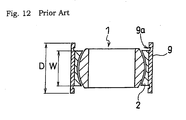
snap rings 5 as shown in Fig. 7, if the depth D of the hole exceeds the width W of theouter race 2, and if ahousing 9 is thin as shown in Fig. 12, a sufficient groove depth for anannular groove 9a is not formed resulting in that thesnap ring 5 may not be firmly retained. - Further, in the method shown in Fig. 8 in which the
housing 3 is bent forming thelocking section 3c engaged with the chamferedsection 2c at the inner periphery of the hole, when thehousing 3 is thin, as shown in Fig. 12, a sufficient thickness cannot be secured for forming thelocking section 3c; and in the method using the screw 7 and thenut 8, as shown in Figs. 9 and 10, when thehousing 3 is thin, sufficient threading cannot be achieved, thus, the screw 7 and thenut 8 are likely to loosen. - The present invention is made in light of the above problems, and it is an object of the present invention to firmly retain an outer race of a bearing to a housing by means of a staking method even under the conditions in which retention of the bearing is difficult as in the related art, namely, when the hole is deeper than the width of the outer race, or when the housing is thin.
- In a bearing retention method according to the present invention, there is provided a bearing retention method in which a bearing is retained in a hole formed in a housing, wherein the bearing is inserted in the hole, the material of the wall of the hole is pushed into the inner part of the hole by means of a staking tool with a diameter larger than that of the hole, and the material is pressed to contact with an end face of the outer race with the staking tool, thereby forming a locking section for retaining the outer race.
- In the present invention, even if the wall of the housing, where the hole is formed, is thin, an amount of material necessary for forming the locking section can be obtained by taking a small amount from the entire area of the wall of the hole in such a manner as to push the material of the hole toward the center of the hole. The necessary amount of material as a whole is thus secured, and the material is pressed to contact with the end face of the outer race to form the locking section achieving a sufficient strength.
- In the bearing retention method according to the present invention, preferably, there is provided a step in advance for retaining the outer race at an end of the area to which the bearing is to be retained in the hole, and after an end of the outer race is brought into contact with the step, the locking section is formed at a position corresponding to another end of the outer race.
- In the present invention, preferably, the position of the one end of the outer race of the bearing is determined by the step formed in advance in the hole and the other end of the outer race is retained by the locking section formed by the method according to the present invention.
- In the bearing retention method according to the present invention, preferably, a projection which can be press fitted in the hole is formed in advance, a concave section corresponding to the projection is formed in advance in the hole, and after the projection of the outer race is engaged with the concave section of the hole, the locking section is formed at a position corresponding to the other end of the outer race.
- In the present invention, preferably, when the bearing is inserted in the hole, the projection formed in advance at the other end of the outer race is engaged with the concave section, which is formed in advance in the hole, whereby positioning of the outer race relative to the hole is performed in advance. After that, the other end of the outer race is retained by the locking section formed by the method according to the present invention.
- In the bearing retention method according to the present invention, preferably, the projections in which the outer race may be press fitted, are formed adjacent to both ends of the area to which the bearing is to be retained in the hole, and after the outer race is press fitted, the locking sections are formed.
- In the present invention, preferably, when the bearing is inserted in the hole, the outer race is positioned in advance with respect to the hole by the projections formed in advance adjacent to both ends of the area to which the bearing is to be retained in the hole. After that, the both ends of the outer race are retained by the locking sections formed by the method of the present invention.
- In addition, in the bearing retention method according to the present invention, preferably, the projection is formed in advance at the end of the outer race, the concave section matching to the convex section is formed in advance in the hole, and after the projection of the outer race is engaged with the concave section of the hole, the locking section is formed at a position corresponding to the end of the outer race.
- In the present invention, preferably, when the bearing is inserted in the hole, the projection formed in advance at the end of the outer race is engaged with the concave section , which is formed in advance at the hole matching the projection formed on the outer race, thus, the outer race is positioned in advance with respect to the hole and the bearing is retained in a direction to engage the bearing with the hole. After that, the end of the outer race is retained in the direction in which the bearing is disengaged from the hole by the locking section formed by the method of the present invention.
-
- Fig. 1 is a cross sectional view showing a state in which an outer race of a spherical bearing is retained to a thin housing by a bearing retention method according to a first embodiment of the present invention, wherein the part below line A - A shows a state before staking and the part above line A - A shows a state after staking;
- Fig. 2 is a cross sectional view showing a state in which the outer race of the spherical bearing is retained to the thin housing by a bearing retention method according to a second embodiment of the present invention;
- Figs. 3A and 3B are cross sectional views showing states in which the outer race of the spherical bearing is retained to the thin housing by a bearing retention method according to a third embodiment of the present invention, wherein Fig. 3A partially shows a state before staking and Fig. 3B partially shows a state after staking;
- Figs. 4A and 4B are cross sectional views showing states in which the outer race of the spherical bearing is retained to the thin housing by a bearing retention method according to a fourth embodiment of the present invention, wherein Fig. 4A partially shows a state before staking and Fig. 4B partially shows a state after staking;
- Figs. 5A and 5B are cross sectional views showing states in which the outer race of the spherical bearing is retained to the thin housing by a bearing retention method according to a fifth embodiment of the present invention, wherein Fig. 5A partially shows a state before staking and Fig. 5B partially shows a state after staking;
- Fig. 6 is a cross sectional view showing a state in which the outer race of the spherical bearing is retained to a housing by staking, according to the conventional art;
- Fig. 7 is a cross sectional view showing a state in which the outer race of the bearing is retained to the housing by a retention method using a snap ring, according to the conventional art;
- Fig. 8 is a cross sectional view showing a state in which the outer race of the spherical bearing is retained to the housing by staking, according to the conventional art;
- Fig. 9 is a cross sectional view showing a state in which the outer race is retained to the housing in such a manner that a tapped hole is formed in the housing, into which a screw is fitted, according to the conventional art;
- Fig. 10 is a cross sectional view showing a state in which the outer race of the spherical bearing is retained to the housing using a flange-shaped step and a nut, according to the conventional art;
- Fig. 11 is a cross sectional view for explaining a problem in the conventional art in Fig. 6; and
- Fig. 12 is a cross sectional view for explaining a problem in the conventional art in Fig. 7.
-
- Embodiments of the present invention will be described hereinbelow with reference to the accompanying drawings. Here, parts identical or corresponding to those of the related art are given the same reference numerals throughout, and a detailed description will be omitted.
- Fig. 1 is a cross sectional view showing a state in which an
outer race 2 of aspherical bearing 1 is retained to athin housing 9, by a bearing retention method according to a first embodiment of the present invention. In the drawing, the part below line A - A shows a state before staking and the part above line A - A shows a state after staking. - First, the
spherical bearing 1 is inserted in a hole of thethin housing 9. In this instance, thespherical bearing 1 can be inserted in the hole smoothly by forming atapered surface 9b near an opening of the hole of thethin housing 9. Next, staking is performed to the material of the hole using astaking tool 10 with a diameter larger than that of the hole. Thetapered surface 9b in the vicinity of the opening of the hole can also make the contact of thestaking tool 10 during staking more smooth. The material of the hole is pushed toward the center of the hole with thestaking tool 10 and is thus pressed to contact with anend face 2a of theouter race 2 thereby forming alocking section 9c. In practice, thestaking tools 10 are simultaneously squeezed from both the upper and lower sides of the hole of thethin housing 9 forming the lockingsections 9c at the upper and lower sides at the same time. - According to the present invention, the material of the hole is squeezed using the
staking tool 10 with a diameter larger than that of the hole so that an amount of material necessary for forming thelocking section 9c for retaining theouter race 2 to the hole is formed only using a small part of the entire area of the wall of the hole. The necessary amount of the material can be secured as a whole while the squeezed material is pressed to contact with theend face 2a of the outer-race 2 using thestaking tool 10 so as to form thelocking section 9c obtaining a sufficient strength. Also, since the material is formed from only a small part of the entire area of the wall of the hole, there can be found no decrease in strength and deformation as to the thin housing. - According to the first embodiment of the present invention, the depth D of the hole is exceeds the width W of the
outer race 2, and also thespherical bearing 1 can be retained to thethin housing 9 by staking so that thespherical bearing 1 can be firmly retained to thethin housing 9 at low cost. - A second embodiment of the present invention will be described with reference to Fig. 2. Here, parts identical or corresponding to those in the first embodiment of the present invention are denoted by the same numerals and a detailed description will be omitted.
- In the second embodiment of the present invention, a
step 9d for retaining theouter race 2 is provided in advance at an end of the area to which thespherical bearing 1 is to be retained in the hole of thethin housing 9. Thespherical bearing 1 is then inserted in the hole of thethin housing 9 at one end (a lower end) of theouter race 2 supporting by thestep 9d. After that, thelocking section 9c is formed at another end (upper end) of theouter race 2 by a method similar to that of the first embodiment of the present invention. - According to the second embodiment of the present invention, when retaining the
spherical bearing 1 in the hole of thethin housing 9, the position of the one end of theouter race 2 of thespherical bearing 1 can be accurately determined by thestep 9d previously formed in the hole, thereby improving the positional accuracy when the coupling is complete. Also, by retaining the other end of theouter race 2 with thelocking section 9c, thespherical bearing 1 is retained to thethin housing 9 by staking, thus, thespherical bearing 1 can be firmly secured at low cost. - Subsequently, a third embodiment of the present invention will be described with reference to Figs. 3A and 3B. Both Fig. 3A and Fig. 3B are partial diagrammatic views showing a state of pre-staking and post-staking respectively. Parts identical or corresponding to those in the first and second embodiments of the present invention are denoted by the same numerals and a detailed description will be omitted.
- In the third embodiment of the present invention, similarly to the embodiment in Fig. 2, the
step 9d where theouter race 2 is retained is provided in advance at the end of the area to which thespherical bearing 1 is retained. Furthermore, aprojection 2d at a size permitting squeezing into the hole is formed in advance to the other end of theouter race 2, in the while aconcave section 9e matching theprojection 2d is formed in advance in the hole. After theprojection 2d of theouter race 2 is engaged with theconcave section 9e of the hole, thelocking section 9c is formed by the method similar to that of the first embodiment of the present invention, as shown in Fig. 3B. - In addition, the
projection 2d of theouter race 2 and theconcave section 9e of the hole may be connected with each other like a ring, or alternatively may separately be formed at one position or a plurality of positions. When theprojection 2d of theouter race 2 and theconcave section 9e of the hole are separately formed at the one position or the plurality of positions, they work for preventing theouter race 2 and thethin housing 9 from being rotated. Also, when theprojection 2d of theouter race 2 and theconcave section 9e of the hole are connected to form a ring, theprojection 2d of theouter race 2 can easily be engaged with theconcave section 9e of the hole without considering the phase of theouter race 2 relative to thethin housing 9. - According to the third embodiment of the present invention, when the
spherical bearing 1 is inserted in the hole, theprojection 2d formed at the other end of the outer race is engaged with theconcave section 9e formed at the hole, thereby enabling theouter race 2 to be positioned in advance with respect to thethin housing 9. Accordingly, a specified positioning accuracy can be obtained before staking so that the positioning accuracy upon completion of retention can be further improved. Also, by retaining the other end of theouter race 2 with thelocking section 9c, thespherical bearing 1 can be retained to thethin housing 9 by staking, thereby enabling thespherical bearing 1 to be firmly secured at low cost. - Next, a fourth embodiment of the present invention will be described with reference to Figs. 4A and 4B. Both Fig. 4A and Fig. 4B are partial diagrammatic views showing a state of pre-staking and post-staking respectively. Parts identical or corresponding to those in the first to third embodiments of the present invention are denoted by the same numerals and a detailed description will be omitted.
- In the fourth embodiment of the present invention,
projections 9f in a size permitting theouter race 2 be press fitted into the housing are formed in advance adjacent to both sides of the area to which thespherical bearing 1 is retained in the hole of thethin housing 9. Theprojections 9f may be connected to form a ring, or alternatively, may be separately formed at one position or at a plurality of positions. Thespherical bearing 1 is then inserted in the hole of thethin housing 9. After theouter race 2 is press fitted in the hole, the lockingsections 9c are formed by a method similar to that of the first embodiment of the present invention, thereby retaining both ends of theouter race 2 with the lockingsections 9c. In addition, the lockingsections 9c formed in this instance are formed by collecting both the material obtained from the wall of the hole and theprojection 9f. - According to the fourth embodiment of the present invention, when the
spherical bearing 1 is inserted in the hole, theouter race 2 can be positioned in advance with respect to the hole by theprojections 9f formed in a manner adjacent to both ends of the area to which thespherical bearing 1 is coupled in the hole. Accordingly, a specified positioning accuracy can be obtained before staking, thereby improving the accuracy when the retaining is completed. Also, since the lockingsections 9c are formed at both ends of theouter race 2, thespherical bearing 1 can be retained to thethin housing 9 by staking, whereby thespherical bearing 1 can be firmly retained at low cost. - Subsequently, a fifth embodiment of the present invention will be described with reference to Figs. 5A and 5B. Fig. 5A and Fig. 5B are partial diagrammatic views showing a state of pre-staking and pro- staking respectively. Parts identical or corresponding to those in the first to fourth embodiments of the present invention are denoted by the same numerals and a detailed description will be omitted.
- In the fifth embodiment of the present invention, a
projection 2e is formed at an end (upper end) of theouter race 2 of thespherical bearing 1, and aconcave section 9g matching theprojection 2e is formed in the hole in advance. While theprojections 9f may be connected with each other to form a ring, or alternatively, may be separately formed at one position or at a plurality of positions, in any case, theprojections 9f have a sufficient strength for supporting the load applied to thespherical bearing 1. When thespherical bearing 1 is inserted in the hole of thethin housing 9, theprojection 2e of theouter race 2 is engaged with theconcave section 9g of the hole, and thelocking section 9c is then formed at a position matching the end (upper end) of theouter race 2 by the method similar to that of the first embodiment of the present invention. - According to the fifth embodiment of the present invention, when the
spherical bearing 1 is inserted in the hole, theprojection 2e formed at the end of theouter race 2 is engaged with theconcave section 9g formed at the hole, so that theouter race 2 can preliminarily be positioned with respect to the hole and thespherical bearing 1 can be retained in the direction inserting the bearing in the hole(downward). Accordingly, the positioning accuracy can be improved when the retaining is completed. Also, since the end of theouter race 2 is retained with thelocking section 9c, thespherical bearing 1 can be retained to thethin housing 9 by staking, and consequently, thespherical bearing 1 can be firmly retained at low cost. - As described above, according to the first to fifth embodiments of the present invention, the bearing can be reliably retained by staking even under conditions difficult in the related arts such that the depth D of the hole exceeds the width W of the
outer race 2, or thespherical bearing 1 is retained to thethin housing 9. In addition, although the present invention examples thespherical bearing 1 retained to thethin housing 9, the invention is not limited thereto and may be applied to any other bearings with an outer race. - Since the present invention is thus constructed, the outer race of the bearing can be reliably retained to the housing by staking irrespective of the relation between the depth of the hole and the width of the outer race or the thickness of the housing. Consequently, the bearing can be firmly retained to the housing at low cost.
Claims (5)
- A method of retaining a bearing in a hole formed in a housing, comprising the process of:inserting the bearing in the hole;pushing material of the wall of the hole toward the center of the hole using a staking tool with a diameter larger than that of the hole;pressing the material so as to contact with an end face of the outer race using the staking tool; andforming a locking section for retaining the outer race.
- The bearing retention method according to Claim 1, further comprising the process of:forming a step for retaining the outer race in advance at an end of the area within the hole to which the bearing is retained hole;bringing an end of the outer race to contact the step; andforming the locking section to another end of the outer race.
- The bearing retention method according to Claim 2, further comprising the process of:forming in advance a projection at the other end of the outer race;forming in advance a concave section corresponding to the projection in the hole;engaging the projection of the outer race with the concave section in the hole; andforming the locking section matching the other end of the outer race.
- The bearing retention method according to Claim 1, further comprising the process of:forming in advance projections in the hole, adjacent to each other within the area to which the outer race of the bearing is retained; ;press fitting the outer race therebetween; andforming the locking sections.
- The bearing retention method according to Claim 1, further comprising the process of:forming in advance a projection at an end of the outer race;forming in advance a concave section matching the projection in the hole;engaging the projection of the outer race with the concave section of the hole; andforming the locking section corresponding to the end of the outer race.
Applications Claiming Priority (2)
| Application Number | Priority Date | Filing Date | Title |
|---|---|---|---|
| JP2001011757A JP2002213468A (en) | 2001-01-19 | 2001-01-19 | Bearing fixing method |
| JP2001011757 | 2001-01-19 |
Publications (2)
| Publication Number | Publication Date |
|---|---|
| EP1225350A1 true EP1225350A1 (en) | 2002-07-24 |
| EP1225350B1 EP1225350B1 (en) | 2006-10-04 |
Family
ID=18878856
Family Applications (1)
| Application Number | Title | Priority Date | Filing Date |
|---|---|---|---|
| EP02001287A Expired - Lifetime EP1225350B1 (en) | 2001-01-19 | 2002-01-18 | Retention method of a bearing |
Country Status (4)
| Country | Link |
|---|---|
| US (3) | US20020095790A1 (en) |
| EP (1) | EP1225350B1 (en) |
| JP (1) | JP2002213468A (en) |
| DE (1) | DE60215062T2 (en) |
Cited By (2)
| Publication number | Priority date | Publication date | Assignee | Title |
|---|---|---|---|---|
| EP1837538A3 (en) * | 2006-03-21 | 2011-01-19 | Roller Bearing Company of America, Inc. | Spherical plain bearing and a housing in combination with a spherical plain bearing |
| CN112303133A (en) * | 2020-10-20 | 2021-02-02 | 八环科技集团股份有限公司 | Assembling process of self-lubricating joint bearing |
Families Citing this family (8)
| Publication number | Priority date | Publication date | Assignee | Title |
|---|---|---|---|---|
| US20050047696A1 (en) * | 2003-08-28 | 2005-03-03 | Serrels Dana M. | Apparatus and method for retaining bearings |
| JP2007157237A (en) * | 2005-12-05 | 2007-06-21 | Kenwood Corp | Pickup unit |
| US20160017913A1 (en) * | 2014-07-16 | 2016-01-21 | Spyraflo, Inc. | Selectively orientable static bearing assembly |
| US10393179B2 (en) * | 2014-10-01 | 2019-08-27 | Schaublin Sa | Segmented outer ring for a bearing for mitigating torque degradation |
| CN110182373B (en) | 2015-01-07 | 2023-01-10 | 洛德公司 | Bearing assemblies for aircraft engine mounts |
| US11111106B2 (en) * | 2017-05-26 | 2021-09-07 | Tim Ebeling | Suspension member equalization system for elevators |
| US12098762B2 (en) * | 2022-09-16 | 2024-09-24 | Gates Corporation | Low axial runout driven pulley through the application of a spindle shaft utilizing multiple sets of bearings with radial clearance to the shaft |
| IT202300017616A1 (en) * | 2023-08-25 | 2025-02-25 | Mme Next Holding Srl | JOINT TERMINAL |
Citations (5)
| Publication number | Priority date | Publication date | Assignee | Title |
|---|---|---|---|---|
| US4337559A (en) * | 1977-03-17 | 1982-07-06 | Heim Universal Corporation | Rod end and a method and apparatus for the manufacture thereof |
| EP0632207A1 (en) * | 1993-06-30 | 1995-01-04 | The Torrington Company | Spherical bearing and method of assembly |
| DE29809031U1 (en) * | 1998-05-19 | 1998-09-24 | Skf Gmbh | Axial fastening device |
| DE19935469A1 (en) * | 1999-07-28 | 2000-05-11 | Skf Gmbh | Method for fixing at least one bearing in bearing endshield with recess for reception of bearing |
| JP2000179537A (en) * | 1998-12-18 | 2000-06-27 | Somic Ishikawa:Kk | Ball joint |
Family Cites Families (18)
| Publication number | Priority date | Publication date | Assignee | Title |
|---|---|---|---|---|
| US2427072A (en) * | 1943-08-04 | 1947-09-09 | Cons Vultee Aircraft Corp | Method of mounting bearings in plates |
| US2906005A (en) * | 1956-03-19 | 1959-09-29 | Racine Ind Plant Inc | Method of securing needle bearings in nylon gears |
| US2904874A (en) * | 1956-11-20 | 1959-09-22 | Thompson Ramo Wooldridge Inc | Method of manufacturing connecting rod bearings |
| US2952901A (en) * | 1957-11-21 | 1960-09-20 | Adamson Stephens Mfg Co | Method of making a rod end bearing |
| US3068552A (en) * | 1960-03-21 | 1962-12-18 | Chain Belt Co | Method of making a bearing |
| US3444606A (en) * | 1967-01-23 | 1969-05-20 | Cecil B Jones | Self-aligning bearing-staking tool |
| US3656221A (en) * | 1970-02-02 | 1972-04-18 | Moog Industries Inc | Method of assembly of joint devices and apparatus therefor |
| US3662462A (en) * | 1970-02-09 | 1972-05-16 | Rohr Corp | Method of securing a bearing race within a bore in a housing |
| FR2084300A5 (en) * | 1970-03-09 | 1971-12-17 | Glacier Metal Co Ltd | |
| US4189821A (en) * | 1977-09-19 | 1980-02-26 | Auto Specialties Manufacturing Company | Method of manufacturing screw jack tubes |
| US4442586A (en) * | 1978-10-16 | 1984-04-17 | Ridenour Ralph Gaylord | Tube-to-tube joint method |
| US4428105A (en) * | 1982-01-04 | 1984-01-31 | General Dynamics Corporation | Bearing staking tool and method |
| DE3522461A1 (en) * | 1985-06-22 | 1987-01-02 | Roland Man Druckmasch | MOUNTING OF RUNNERS |
| JP3097761B2 (en) * | 1991-03-19 | 2000-10-10 | ティーアールダブリュ オートモーティブ ジャパン株式会社 | Joint |
| JP3531836B2 (en) * | 1992-06-18 | 2004-05-31 | オイレス工業株式会社 | Spherical bearing and manufacturing method thereof |
| DE19805237B4 (en) * | 1998-02-10 | 2005-12-08 | Skf Gmbh | end shield |
| DE10001575C2 (en) * | 2000-01-15 | 2003-01-02 | Skf Gmbh | Method for fixing at least one bearing in a bearing seat |
| US6666583B2 (en) * | 2001-12-04 | 2003-12-23 | Visteon Global Technologies, Inc. | Bearing retention assembly having cam chamfered bearing race ring |
-
2001
- 2001-01-19 JP JP2001011757A patent/JP2002213468A/en active Pending
-
2002
- 2002-01-18 US US10/050,830 patent/US20020095790A1/en not_active Abandoned
- 2002-01-18 DE DE60215062T patent/DE60215062T2/en not_active Expired - Fee Related
- 2002-01-18 EP EP02001287A patent/EP1225350B1/en not_active Expired - Lifetime
-
2004
- 2004-04-28 US US10/833,317 patent/US20040194314A1/en not_active Abandoned
-
2005
- 2005-03-21 US US11/083,949 patent/US20050160601A1/en not_active Abandoned
Patent Citations (5)
| Publication number | Priority date | Publication date | Assignee | Title |
|---|---|---|---|---|
| US4337559A (en) * | 1977-03-17 | 1982-07-06 | Heim Universal Corporation | Rod end and a method and apparatus for the manufacture thereof |
| EP0632207A1 (en) * | 1993-06-30 | 1995-01-04 | The Torrington Company | Spherical bearing and method of assembly |
| DE29809031U1 (en) * | 1998-05-19 | 1998-09-24 | Skf Gmbh | Axial fastening device |
| JP2000179537A (en) * | 1998-12-18 | 2000-06-27 | Somic Ishikawa:Kk | Ball joint |
| DE19935469A1 (en) * | 1999-07-28 | 2000-05-11 | Skf Gmbh | Method for fixing at least one bearing in bearing endshield with recess for reception of bearing |
Non-Patent Citations (1)
| Title |
|---|
| PATENT ABSTRACTS OF JAPAN vol. 2000, no. 09 13 October 2000 (2000-10-13) * |
Cited By (3)
| Publication number | Priority date | Publication date | Assignee | Title |
|---|---|---|---|---|
| EP1837538A3 (en) * | 2006-03-21 | 2011-01-19 | Roller Bearing Company of America, Inc. | Spherical plain bearing and a housing in combination with a spherical plain bearing |
| CN112303133A (en) * | 2020-10-20 | 2021-02-02 | 八环科技集团股份有限公司 | Assembling process of self-lubricating joint bearing |
| CN112303133B (en) * | 2020-10-20 | 2022-02-22 | 八环科技集团股份有限公司 | Assembling process of self-lubricating joint bearing |
Also Published As
| Publication number | Publication date |
|---|---|
| EP1225350B1 (en) | 2006-10-04 |
| DE60215062D1 (en) | 2006-11-16 |
| JP2002213468A (en) | 2002-07-31 |
| US20040194314A1 (en) | 2004-10-07 |
| DE60215062T2 (en) | 2007-02-15 |
| US20050160601A1 (en) | 2005-07-28 |
| US20020095790A1 (en) | 2002-07-25 |
Similar Documents
| Publication | Publication Date | Title |
|---|---|---|
| US4834676A (en) | Solderless wedge-lock coaxial cable connector | |
| EP1225350B1 (en) | Retention method of a bearing | |
| US6039475A (en) | Retainer for roller bearing and method for manufacturing the same | |
| US20020001513A1 (en) | Clip | |
| RU2410578C2 (en) | Threaded nut, procedure for its fabrication and tool used for this procedure | |
| JPH0829392B2 (en) | Pierce nut manufacturing equipment | |
| CA2118732C (en) | Method of manufacturing tee nut | |
| EP1493937A1 (en) | Method of manufacturing spring assembly | |
| EP2746605B1 (en) | Assembling method of bearing unit | |
| GB2358227A (en) | Method of retaining a bearing and a bearing assembly produced therewith | |
| US3626566A (en) | Method of forming a ball and socket joint | |
| US7673487B2 (en) | Method for forming hollow shaft with a flange and product with hollow shaft formed by the same | |
| US20100313725A1 (en) | Puncher | |
| US10879681B2 (en) | Coupling for electrical metallic tubing | |
| US4747203A (en) | Production method for ball support structures | |
| JPH06280864A (en) | Needle roller bearing | |
| CN110088491A (en) | The manufacturing method of washer and washer | |
| US2018701A (en) | Ball and similar bearing and method of manufacturing the same | |
| US9587679B2 (en) | Method and apparatus for manufacturing rolling-element bearing | |
| JPS6126711Y2 (en) | ||
| US20210122015A1 (en) | Ratchet wrench and method for assembling the same | |
| JPS58176035A (en) | Manufacture of hose mouthpiece | |
| CN220921150U (en) | Roller type pitch circle clamp tool with tooth slot positioning function | |
| US20250353068A1 (en) | Button key | |
| JP2001303834A (en) | Anti-seismic hinge and manufacturing method thereof |
Legal Events
| Date | Code | Title | Description |
|---|---|---|---|
| PUAI | Public reference made under article 153(3) epc to a published international application that has entered the european phase |
Free format text: ORIGINAL CODE: 0009012 |
|
| AK | Designated contracting states |
Kind code of ref document: A1 Designated state(s): AT BE CH CY DE DK ES FI FR GB GR IE IT LI LU MC NL PT SE TR |
|
| AX | Request for extension of the european patent |
Free format text: AL;LT;LV;MK;RO;SI |
|
| 17P | Request for examination filed |
Effective date: 20030116 |
|
| AKX | Designation fees paid |
Designated state(s): DE FR GB IT |
|
| 17Q | First examination report despatched |
Effective date: 20050420 |
|
| GRAP | Despatch of communication of intention to grant a patent |
Free format text: ORIGINAL CODE: EPIDOSNIGR1 |
|
| GRAS | Grant fee paid |
Free format text: ORIGINAL CODE: EPIDOSNIGR3 |
|
| GRAA | (expected) grant |
Free format text: ORIGINAL CODE: 0009210 |
|
| AK | Designated contracting states |
Kind code of ref document: B1 Designated state(s): DE FR GB IT |
|
| PG25 | Lapsed in a contracting state [announced via postgrant information from national office to epo] |
Ref country code: IT Free format text: LAPSE BECAUSE OF FAILURE TO SUBMIT A TRANSLATION OF THE DESCRIPTION OR TO PAY THE FEE WITHIN THE PRESCRIBED TIME-LIMIT;WARNING: LAPSES OF ITALIAN PATENTS WITH EFFECTIVE DATE BEFORE 2007 MAY HAVE OCCURRED AT ANY TIME BEFORE 2007. THE CORRECT EFFECTIVE DATE MAY BE DIFFERENT FROM THE ONE RECORDED. Effective date: 20061004 |
|
| REG | Reference to a national code |
Ref country code: GB Ref legal event code: FG4D |
|
| REF | Corresponds to: |
Ref document number: 60215062 Country of ref document: DE Date of ref document: 20061116 Kind code of ref document: P |
|
| PGFP | Annual fee paid to national office [announced via postgrant information from national office to epo] |
Ref country code: DE Payment date: 20070110 Year of fee payment: 6 |
|
| PGFP | Annual fee paid to national office [announced via postgrant information from national office to epo] |
Ref country code: GB Payment date: 20070119 Year of fee payment: 6 |
|
| ET | Fr: translation filed | ||
| PLBE | No opposition filed within time limit |
Free format text: ORIGINAL CODE: 0009261 |
|
| STAA | Information on the status of an ep patent application or granted ep patent |
Free format text: STATUS: NO OPPOSITION FILED WITHIN TIME LIMIT |
|
| 26N | No opposition filed |
Effective date: 20070705 |
|
| PGFP | Annual fee paid to national office [announced via postgrant information from national office to epo] |
Ref country code: IT Payment date: 20070616 Year of fee payment: 6 |
|
| PGFP | Annual fee paid to national office [announced via postgrant information from national office to epo] |
Ref country code: FR Payment date: 20070111 Year of fee payment: 6 |
|
| GBPC | Gb: european patent ceased through non-payment of renewal fee |
Effective date: 20080118 |
|
| PG25 | Lapsed in a contracting state [announced via postgrant information from national office to epo] |
Ref country code: DE Free format text: LAPSE BECAUSE OF NON-PAYMENT OF DUE FEES Effective date: 20080801 |
|
| REG | Reference to a national code |
Ref country code: FR Ref legal event code: ST Effective date: 20081029 |
|
| PG25 | Lapsed in a contracting state [announced via postgrant information from national office to epo] |
Ref country code: GB Free format text: LAPSE BECAUSE OF NON-PAYMENT OF DUE FEES Effective date: 20080118 |
|
| PG25 | Lapsed in a contracting state [announced via postgrant information from national office to epo] |
Ref country code: FR Free format text: LAPSE BECAUSE OF NON-PAYMENT OF DUE FEES Effective date: 20080131 |
|
| PG25 | Lapsed in a contracting state [announced via postgrant information from national office to epo] |
Ref country code: IT Free format text: LAPSE BECAUSE OF NON-PAYMENT OF DUE FEES Effective date: 20080118 |