EP1225333A2 - Control valve for variable displacement type compressor - Google Patents
Control valve for variable displacement type compressor Download PDFInfo
- Publication number
- EP1225333A2 EP1225333A2 EP02001497A EP02001497A EP1225333A2 EP 1225333 A2 EP1225333 A2 EP 1225333A2 EP 02001497 A EP02001497 A EP 02001497A EP 02001497 A EP02001497 A EP 02001497A EP 1225333 A2 EP1225333 A2 EP 1225333A2
- Authority
- EP
- European Patent Office
- Prior art keywords
- pressure
- chamber
- bellows
- control valve
- movable end
- Prior art date
- Legal status (The legal status is an assumption and is not a legal conclusion. Google has not performed a legal analysis and makes no representation as to the accuracy of the status listed.)
- Withdrawn
Links
Images


Classifications
-
- F—MECHANICAL ENGINEERING; LIGHTING; HEATING; WEAPONS; BLASTING
- F04—POSITIVE - DISPLACEMENT MACHINES FOR LIQUIDS; PUMPS FOR LIQUIDS OR ELASTIC FLUIDS
- F04B—POSITIVE-DISPLACEMENT MACHINES FOR LIQUIDS; PUMPS
- F04B27/00—Multi-cylinder pumps specially adapted for elastic fluids and characterised by number or arrangement of cylinders
- F04B27/08—Multi-cylinder pumps specially adapted for elastic fluids and characterised by number or arrangement of cylinders having cylinders coaxial with, or parallel or inclined to, main shaft axis
- F04B27/14—Control
- F04B27/16—Control of pumps with stationary cylinders
- F04B27/18—Control of pumps with stationary cylinders by varying the relative positions of a swash plate and a cylinder block
-
- F—MECHANICAL ENGINEERING; LIGHTING; HEATING; WEAPONS; BLASTING
- F04—POSITIVE - DISPLACEMENT MACHINES FOR LIQUIDS; PUMPS FOR LIQUIDS OR ELASTIC FLUIDS
- F04B—POSITIVE-DISPLACEMENT MACHINES FOR LIQUIDS; PUMPS
- F04B27/00—Multi-cylinder pumps specially adapted for elastic fluids and characterised by number or arrangement of cylinders
- F04B27/08—Multi-cylinder pumps specially adapted for elastic fluids and characterised by number or arrangement of cylinders having cylinders coaxial with, or parallel or inclined to, main shaft axis
- F04B27/14—Control
- F04B27/16—Control of pumps with stationary cylinders
- F04B27/18—Control of pumps with stationary cylinders by varying the relative positions of a swash plate and a cylinder block
- F04B27/1804—Controlled by crankcase pressure
-
- F—MECHANICAL ENGINEERING; LIGHTING; HEATING; WEAPONS; BLASTING
- F04—POSITIVE - DISPLACEMENT MACHINES FOR LIQUIDS; PUMPS FOR LIQUIDS OR ELASTIC FLUIDS
- F04B—POSITIVE-DISPLACEMENT MACHINES FOR LIQUIDS; PUMPS
- F04B27/00—Multi-cylinder pumps specially adapted for elastic fluids and characterised by number or arrangement of cylinders
- F04B27/08—Multi-cylinder pumps specially adapted for elastic fluids and characterised by number or arrangement of cylinders having cylinders coaxial with, or parallel or inclined to, main shaft axis
- F04B27/14—Control
- F04B27/16—Control of pumps with stationary cylinders
- F04B27/18—Control of pumps with stationary cylinders by varying the relative positions of a swash plate and a cylinder block
- F04B27/1804—Controlled by crankcase pressure
- F04B2027/1809—Controlled pressure
- F04B2027/1813—Crankcase pressure
-
- F—MECHANICAL ENGINEERING; LIGHTING; HEATING; WEAPONS; BLASTING
- F04—POSITIVE - DISPLACEMENT MACHINES FOR LIQUIDS; PUMPS FOR LIQUIDS OR ELASTIC FLUIDS
- F04B—POSITIVE-DISPLACEMENT MACHINES FOR LIQUIDS; PUMPS
- F04B27/00—Multi-cylinder pumps specially adapted for elastic fluids and characterised by number or arrangement of cylinders
- F04B27/08—Multi-cylinder pumps specially adapted for elastic fluids and characterised by number or arrangement of cylinders having cylinders coaxial with, or parallel or inclined to, main shaft axis
- F04B27/14—Control
- F04B27/16—Control of pumps with stationary cylinders
- F04B27/18—Control of pumps with stationary cylinders by varying the relative positions of a swash plate and a cylinder block
- F04B27/1804—Controlled by crankcase pressure
- F04B2027/1822—Valve-controlled fluid connection
- F04B2027/1827—Valve-controlled fluid connection between crankcase and discharge chamber
-
- F—MECHANICAL ENGINEERING; LIGHTING; HEATING; WEAPONS; BLASTING
- F04—POSITIVE - DISPLACEMENT MACHINES FOR LIQUIDS; PUMPS FOR LIQUIDS OR ELASTIC FLUIDS
- F04B—POSITIVE-DISPLACEMENT MACHINES FOR LIQUIDS; PUMPS
- F04B27/00—Multi-cylinder pumps specially adapted for elastic fluids and characterised by number or arrangement of cylinders
- F04B27/08—Multi-cylinder pumps specially adapted for elastic fluids and characterised by number or arrangement of cylinders having cylinders coaxial with, or parallel or inclined to, main shaft axis
- F04B27/14—Control
- F04B27/16—Control of pumps with stationary cylinders
- F04B27/18—Control of pumps with stationary cylinders by varying the relative positions of a swash plate and a cylinder block
- F04B27/1804—Controlled by crankcase pressure
- F04B2027/184—Valve controlling parameter
- F04B2027/185—Discharge pressure
-
- F—MECHANICAL ENGINEERING; LIGHTING; HEATING; WEAPONS; BLASTING
- F04—POSITIVE - DISPLACEMENT MACHINES FOR LIQUIDS; PUMPS FOR LIQUIDS OR ELASTIC FLUIDS
- F04B—POSITIVE-DISPLACEMENT MACHINES FOR LIQUIDS; PUMPS
- F04B27/00—Multi-cylinder pumps specially adapted for elastic fluids and characterised by number or arrangement of cylinders
- F04B27/08—Multi-cylinder pumps specially adapted for elastic fluids and characterised by number or arrangement of cylinders having cylinders coaxial with, or parallel or inclined to, main shaft axis
- F04B27/14—Control
- F04B27/16—Control of pumps with stationary cylinders
- F04B27/18—Control of pumps with stationary cylinders by varying the relative positions of a swash plate and a cylinder block
- F04B27/1804—Controlled by crankcase pressure
- F04B2027/184—Valve controlling parameter
- F04B2027/1854—External parameters
Definitions
- the present invention relates to a control valve for a variable displacement compressor that is used in a refrigerant circuit of a vehicle air conditioner and changes the displacement in accordance with the pressure in a crank chamber.
- the control valve includes, for example, a valve body, a bellows, and a transmission rod.
- the opening degree of the valve body is controlled in accordance with the pressure in a crank chamber.
- the movable end of the bellows is displaced in accordance with the pressure in a suction pressure zone of the refrigerant circuit.
- the transmission rod couples the valve body to the movable end of the bellows so that the valve body integrally moves with the movable end of the bellows.
- the valve body moves by means of the transmission rod.
- the discharge displacement of the compressor is adjusted to cancel the variations of the pressure in the suction pressure zone in accordance with the position of the valve body.
- a measurement error in the bellows during manufacturing may incline the axis of the bellows with respect to the axis of the valve housing. If the inclination of the bellows is great, the bellows contacts the inner wall of a sensing chamber, in which the bellows is accommodated. As a result, the fluctuations of pressure in the suction pressure zone are not reliably communicated to the valve body. That is, the control valve malfunctions.
- a recess is formed on the movable end of the bellows.
- the end of the transmission rod is fitted to the recess.
- the bellows is supported by a valve housing through the transmission rod. Therefore, the inclination of the bellows caused by a measurement error is corrected.
- the elastic bellows generates stress in a direction that intersects the axis of the valve housing. The stress is applied to the transmission rod through the fitted portion. Therefore, the friction between the transmission rod and the valve housing increases due to the stress. As a result, the hysteresis in the operational characteristics of the control valve increases.
- the objective of the present invention is to provide a control valve for a variable displacement compressor that suppresses the inclination of a bellows and prevents the transmission rod from being affected by forces applied by the bellows in a direction that intersects the axial direction.
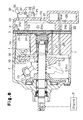
- a control valve CV according to a first embodiment of the present invention will now be described with reference to Figs 1 and 2.
- the control valve CV is used in a variable displacement swash plate type compressor located in a vehicle air conditioner.
- the compressor includes a cylinder block 1, a front housing member 2 connected to the front end of the cylinder block 1, and a rear housing member 4 connected to the rear end of the cylinder block 1.
- a valve plate assembly 3 is located between the rear housing member 4 and the cylinder block 1.
- the cylinder block 1, the front housing member 2, and the rear housing member 4 form the housing of the compressor.
- a drive shaft 6 extends through the crank chamber 5 and is rotatably supported. The drive shaft 6 is connected to and driven by an external drive source, which is an engine E in this embodiment.
- a lug plate 11 is fixed to the drive shaft 6 in the crank chamber 5 to rotate integrally with the drive shaft 6.
- a drive plate which is a swash plate 12 in this embodiment, is accommodated in the crank chamber 5.
- the swash plate 12 slides along the drive shaft 6 and inclines with respect to the axis of the drive shaft 6.
- a hinge mechanism 13 is provided between the lug plate 11 and the swash plate 12. The hinge mechanism 13 and the lug plate 11 cause the swash plate 12 to move integrally with the drive shaft 6.
- Cylinder bores 1a (only one is shown in Fig. 1) are formed in the cylinder block 1 at constant angular intervals around the axis L of the drive shaft 6. Each cylinder bore 1a accommodates a single headed piston 20 such that the piston 20 can reciprocate in the cylinder bore 1a.
- the opening of each cylinder bore 1a is closed by the valve plate assembly 3 and the corresponding piston 20.
- a compression chamber, the volume of which varies in accordance with the reciprocation of the piston 20, is defined in each cylinder bore 1a.
- the front end of each piston 20 is coupled to the periphery of the swash plate 12 through a pair of shoes 19.
- the swash plate 12 is rotated as the drive shaft 6 rotates. Rotation of the swash plate 12 is converted into reciprocation of each piston 20 by the corresponding pair of shoes 19.
- a suction chamber 21 and a discharge chamber 22 are defined between the valve plate assembly 3 and the rear housing member 4.
- the discharge chamber 22 is located about the suction chamber 21.
- the valve plate assembly 3 has suction ports 23, suction valve flaps 24, discharge ports 25, and discharge valve flaps 26. Each set of the suction port 23, the suction valve flap 24, the discharge port 25, and the discharge valve flap 26 corresponds to one of the cylinder bores 1a.
- the refrigerant circuit of the vehicular air-conditioner is made up of the compressor and an external refrigerant circuit 30.
- the external refrigerant circuit 30 connects the discharge chamber 22 to the suction chamber 21, and includes a condenser 31, an expansion valve 32, and an evaporator 33.
- a downstream pipe 35 is located in a downstream portion of the external refrigerant circuit 30.
- the downstream pipe 35 connects the outlet of the evaporator 33 with the suction chamber 21 of the compressor.
- An upstream pipe 36 is located in the upstream portion of the external refrigerant circuit 30.
- the upstream pipe 36 connects the discharge chamber 22 of the compressor with the inlet of the condenser 31.
- the first pressure monitoring point P1 is located in the discharge chamber 22, the pressure of which is equal to that of the most upstream section of the upstream pipe 36.
- the second pressure monitoring point P2 is set midway along the upstream pipe 36 at a position separated from the first pressure monitoring point P1 by a predetermined distance.
- the pressure PdH at the first pressure monitoring point P1 is applied to the displacement control valve CV through a first pressure introduction passage 37.
- the pressure PdL at the second pressure monitoring point P2 is applied to the displacement control valve CV through a second pressure introduction passage 38.
- the control valve CV has a supply control valve portion 59 and a solenoid 60.
- the supply control valve portion 59 controls the opening (throttle amount) of the supply passage 28, which connects the discharge chamber 22 with the crank chamber 5.
- the solenoid 60 serves as an electromagnetic actuator for controlling a transmission rod 40 located in the control valve CV on the basis of an externally supplied electric current. Specifically, the solenoid 60 applies force to a bellows 54, which will be described later, through the transmission rod 40 on the basis of an externally supplied electric current.
- the transmission rod 40 includes a distal end portion 41, a coupler 42, a valve body portion 43, and a guide portion 44.
- the valve body portion 43 is located at the substantial center of the transmission rod 40 and is a part of the guide portion 44.
- a valve housing 45 of the control valve CV has a plug 45a, an upper half body 45b, and a lower half body 45c.
- a valve chamber 46 and a communication passage 47 are defined in the upper half body 45b.
- a pressure sensing chamber 48 is defined between the upper half body 45b and the plug 45a.
- a protrusion 68 is formed on a movable end 54a, which is the lower end of the bellows 54, and faces the transmission rod 40.
- the bellows 54 is installed in a compressed state. Therefore, a lower end surface 68a of the protrusion 68 is pressed against an upper end surface 41a of the distal end portion 41 by the downward force generated by the compression of the bellows 54.
- the movable end 54a, or the bellows 54, and the distal end portion 41, or the transmission rod 40 are relatively displaced in a direction intersecting the axis L of the valve housing 45.
- the first pressure chamber 55 is connected to the first pressure monitoring point P1, which is the discharge chamber 22, through a P1 port 57 formed in the plug 45a, and the first pressure introduction passage 37.
- the second pressure chamber 56 is connected to the second pressure monitoring point P2 through a P2 port 58, which is formed in the upper half body 45b of the valve housing 45, and the second pressure introduction passage 38. Therefore, the first pressure chamber 55 is exposed to the pressure PdH monitored at the first pressure monitoring point P1, and the second pressure chamber 56 is exposed to the pressure PdL monitored at the second pressure monitoring point P2.
- a coil spring 66 is located between the stationary iron core 62 and the movable iron core 64.
- the spring 66 urges the movable iron core 64 away from the stationary iron core 62 and urges the transmission rod 40, or the valve body portion 43, downward as viewed in the drawing.
- a coil 67 is wound about the stationary iron core 62 and the movable iron core 64.
- the coil 67 is connected to a drive circuit 71, and the drive circuit 71 is connected to a controller 70.
- the controller 70 is connected to an external information detector 72.
- the controller 70 receives external information (on-off state of the air conditioner, the temperature of the passenger compartment, and a target temperature) from the detector 72. Based on the received information, the controller 70 commands the drive circuit 71 to supply a drive signal to the coil 67.
- the coil 67 generates an electromagnetic force, the magnitude of which depends on the value of the supplied current, between the stationary iron core 62 and the movable iron core 64.
- the value of the current supplied to the coil 67 is controlled by controlling the voltage applied to the coil 67. In this embodiment, the voltage applied to the coil 67 is duty controlled.
- the opening degree of the control valve CV is determined by the position of the transmission rod 40.
- the movable end 54a of the bellows 54 is supported by the valve housing 45 through the support spring 69, which is fitted to the movable end 54a. Therefore, the inclination of the bellows 54 is corrected by the valve housing 45 through the support spring 69.
- the support spring 69 is located outside the protrusion 68. Therefore, it is easy to apply a relatively large diameter coil spring for the support spring 69. Thus, the flexibility of design is improved.
- the coil spring is used as the support spring 69. Since the coil spring has a center space, the space in the coil spring is used as the recess 69a.
- Fig. 3 illustrates a second embodiment of the present invention.
- the second embodiment is a modification of the first embodiment.
- a recess 81 is formed on the movable end 54a of the bellows 54 and the distal end portion of the support spring 69 is fitted to the recess 81.
- the recess 81 is formed in the internal space of the bellows 54.
- An inner end surface 81a of the recess 81 contacts an upper end surface 41a of the distal end portion 41.
- Fig. 4 illustrates a third embodiment of the present invention.
- the third embodiment is a modification of the first embodiment.
- the lower end surface 68a of the protrusion 68 is semispherical.
- the upper end surface 41a of the distal end portion 41 may be semispherical.
- Fig. 5 illustrates a fourth embodiment of the present invention.
- the fourth embodiment is a modification of the first embodiment.
- the support spring 69 is a conic coil spring. Since the conic coil spring is tough against the bending load, the inclination of the bellows 54 is more reliably corrected.
- a disk spring may be used as the support spring 69.
- a rubber may be used as the elastic member.
- Fig. 6 illustrates a fifth embodiment of the present invention.
- the fifth embodiment is a modification of the first embodiment.
- the first pressure monitoring point P1 is located in the suction pressure zone, which includes the evaporator 33 and the suction chamber 21.
- the first pressure monitoring point P1 is located in the downstream pipe 35.
- the second pressure monitoring point P2 is also located in the suction pressure zone and downstream of the first pressure monitoring point P1.
- the second pressure monitoring point P2 is located in the suction chamber 21.
- the first pressure monitoring point P1 may be located in the discharge pressure zone, which includes the discharge chamber 22 and the condenser 31, and the second pressure monitoring point P2 may be located in the suction pressure zone, which includes the evaporator 33 and the suction chamber 21.
- the solenoid 60 which is externally controlled, may be eliminated from the control valve CV and the control valve CV may be an internal control valve.
- the pressure sensing member of the control valve CV may be operated in accordance with one of the suction pressure Ps, the crank chamber pressure Pc, or the discharge pressure Pd.
- the pressure monitoring point P1 may be provided in the embodiments illustrated in Figs. 1 to 6 and the second pressure chamber 56 may be exposed to the atmosphere (constant pressure) or may be vacuumed.
- the control valve CV may be used as a bleed control valve for controlling the crank chamber pressure Pc by controlling the opening of the bleed passage 27 instead of the supply passage 28.
- the present invention may be embodied in a control valve of a wobble type variable displacement compressor.
Landscapes
- Engineering & Computer Science (AREA)
- Mechanical Engineering (AREA)
- General Engineering & Computer Science (AREA)
- Compressors, Vaccum Pumps And Other Relevant Systems (AREA)
- Control Of Positive-Displacement Pumps (AREA)
- Details Of Reciprocating Pumps (AREA)
Abstract
Description
Claims (11)
- A control valve used for a variable displacement compressor installed in a refrigerant circuit, wherein the compressor varies the displacement in accordance with the pressure in a crank chamber (5), wherein the compressor has a control passage (27, 28), which connects the crank chamber (5) to a pressure zone in which the pressure is different from the pressure of the crank chamber (5), the control valve comprising:a valve housing (45);a valve chamber (46) defined in the valve housing (45);a valve body (43), which is accommodated in the valve chamber (46) for adjusting the opening degree of the control passage (27, 28);a pressure sensing chamber (48) defined in the valve housing (45), wherein the pressure at a pressure monitoring point in the refrigerant circuit is applied to the pressure sensing chamber (48);a bellows (54), which is located in the pressure sensing chamber (48), wherein the bellows (54) has a movable end (54a);a transmission rod (40) slidably supported by the valve housing (45) between the valve chamber (46) and the pressure sensing chamber (48), wherein the transmission rod (40) moves the valve body (43) in accordance with the displacement of the bellows (54), wherein the bellows (54) is displaced in accordance with the variations of the pressure in the pressure sensing chamber (48) thereby moving the valve body (43) such that the displacement of the compressor is adjusted to cancel the variations of the pressure in the pressure sensing chamber (48), and wherein the movable end (54a) of the bellows (54) and the transmission rod (40) contact each other and can be relatively displaced in a direction intersecting the axis of the valve housing (45), the control valve being characterized by:an elastic member (69) located between the inner wall of the pressure sensing chamber (48) and the movable end (54a) of the bellows (54), wherein the elastic member (69) elastically supports the movable end (54a) such that the movable end (54a) can be displaced, and wherein one of the elastic member (69) and the movable end (54a) of the bellows (54) includes a recess (69a, 81) and the other one includes a protrusion (68) such that the elastic member (69) and the movable end (54a) of the bellows (54) are fitted to each other.
- The control valve according to claim 1, characterized in that the recess (69a) is arranged on the elastic member (69), and the protrusion (68) is arranged on the movable end (54a) of the bellows (54).
- The control valve according to claim 1, characterized in that the protrusion is arranged on the elastic member (69), and the recess (81) is arranged on the movable end (54a) of the bellows (54).
- The control valve according to any one of claims 1 to 3, characterized in that the elastic member (69) is a coil spring.
- The control valve according to claim 4, characterized in that the coil spring is conic.
- The control valve according to claim 1, characterized in that the protrusion is semispherical.
- The control valve according to any one of claims 1 to 6, characterized in that the bellows (54) define a first pressure chamber (55) and a second pressure chamber (56) in the pressure sensing chamber (48), and wherein the pressure at a first pressure monitoring point (P1) in the refrigerant circuit is applied to the first pressure chamber (55), and the pressure at a second pressure monitoring point (P2), which is downstream of the first pressure monitoring point (P1), is applied to the second pressure chamber (56).
- The control valve according to claim 7, characterized in that the bellows (54) is displaced in accordance with the variations of the pressure difference between the first pressure chamber (55) and the second pressure chamber (56).
- The control valve according to claims 7 or 8, characterized in that the refrigerant circuit has a discharge pressure zone, and wherein the first and the second pressure monitoring points (P1, P2) are located in the discharge pressure zone.
- The control valve according to claims 7 or 8, characterized in that the refrigerant circuit has a suction pressure zone, and wherein the first and the second pressure monitoring points (P1, P2) are located in the suction pressure zone.
- The control valve according to any one of claims 7 to 10 further being characterized by an actuator (60) for applying force to the bellows (54) in accordance with an externally supplied electric current, wherein the force applied by the actuator (60) reflects the target value of the pressure difference between the first pressure chamber (55) and the second pressure chamber (56), and wherein the bellows (54) moves the valve body (43) such that the pressure difference seeks to the target value.
Applications Claiming Priority (2)
| Application Number | Priority Date | Filing Date | Title |
|---|---|---|---|
| JP2001014615A JP2002221153A (en) | 2001-01-23 | 2001-01-23 | Control valve for variable displacement type compressor |
| JP2001014615 | 2001-01-23 |
Publications (2)
| Publication Number | Publication Date |
|---|---|
| EP1225333A2 true EP1225333A2 (en) | 2002-07-24 |
| EP1225333A3 EP1225333A3 (en) | 2004-01-21 |
Family
ID=18881283
Family Applications (1)
| Application Number | Title | Priority Date | Filing Date |
|---|---|---|---|
| EP02001497A Withdrawn EP1225333A3 (en) | 2001-01-23 | 2002-01-22 | Control valve for variable displacement type compressor |
Country Status (6)
| Country | Link |
|---|---|
| US (1) | US6682314B2 (en) |
| EP (1) | EP1225333A3 (en) |
| JP (1) | JP2002221153A (en) |
| KR (1) | KR100462032B1 (en) |
| CN (1) | CN1230621C (en) |
| BR (1) | BR0200190A (en) |
Families Citing this family (21)
| Publication number | Priority date | Publication date | Assignee | Title |
|---|---|---|---|---|
| JP2004067042A (en) * | 2002-08-09 | 2004-03-04 | Tgk Co Ltd | Air-conditioner |
| JP2004144462A (en) * | 2002-08-26 | 2004-05-20 | Tgk Co Ltd | Operation method for refrigeration cycle |
| JP2004098757A (en) * | 2002-09-05 | 2004-04-02 | Toyota Industries Corp | Air conditioner |
| JP2004162567A (en) * | 2002-11-12 | 2004-06-10 | Fuji Koki Corp | Control valve for variable displacement compressor |
| JP4118181B2 (en) * | 2003-03-28 | 2008-07-16 | サンデン株式会社 | Control valve for variable displacement swash plate compressor |
| JP4316955B2 (en) * | 2003-08-11 | 2009-08-19 | イーグル工業株式会社 | Capacity control valve |
| JP4456906B2 (en) * | 2004-03-25 | 2010-04-28 | 株式会社不二工機 | Control valve for variable capacity compressor |
| JP2007138785A (en) * | 2005-11-16 | 2007-06-07 | Toyota Industries Corp | Control device for vehicular refrigeration circuit, variable displacement compressor and control valve for variable displacement compressor |
| CN101469696A (en) * | 2007-12-27 | 2009-07-01 | 上海三电贝洱汽车空调有限公司 | Electrical controlled valve of variable displacement compressor |
| KR100986939B1 (en) * | 2008-08-01 | 2010-10-12 | 학교법인 두원학원 | Capacity control valve of variable displacement compressor |
| JP5235569B2 (en) * | 2008-09-12 | 2013-07-10 | サンデン株式会社 | Capacity control valve, variable capacity compressor and capacity control system of variable capacity compressor |
| KR101159500B1 (en) * | 2012-05-17 | 2012-06-22 | 주식회사 코다코 | Capacity control valve of variable displacement compressor |
| JP6193291B2 (en) * | 2015-04-13 | 2017-09-06 | 三井造船株式会社 | Fuel supply device |
| JP6141930B2 (en) | 2015-09-16 | 2017-06-07 | 株式会社豊田自動織機 | Capacity control valve |
| US11754194B2 (en) | 2019-04-03 | 2023-09-12 | Eagle Industry Co., Ltd. | Capacity control valve |
| CN113646531A (en) | 2019-04-03 | 2021-11-12 | 伊格尔工业股份有限公司 | volume control valve |
| CN116518113A (en) | 2019-04-03 | 2023-08-01 | 伊格尔工业股份有限公司 | Capacity control valve |
| JP7399950B2 (en) * | 2019-04-03 | 2023-12-18 | イーグル工業株式会社 | capacity control valve |
| EP3961033B1 (en) | 2019-04-24 | 2025-03-12 | Eagle Industry Co., Ltd. | Capacity control valve |
| EP3961075A4 (en) | 2019-04-24 | 2023-01-04 | Eagle Industry Co., Ltd. | Capacity control valve |
| KR102862886B1 (en) | 2020-04-22 | 2025-09-23 | 이구루코교 가부시기가이샤 | Capacity control valve |
Family Cites Families (10)
| Publication number | Priority date | Publication date | Assignee | Title |
|---|---|---|---|---|
| JP2943934B2 (en) * | 1990-03-20 | 1999-08-30 | サンデン株式会社 | Variable capacity swash plate compressor |
| US6010312A (en) * | 1996-07-31 | 2000-01-04 | Kabushiki Kaisha Toyoda Jidoshokki Seiksakusho | Control valve unit with independently operable valve mechanisms for variable displacement compressor |
| JP3789023B2 (en) * | 1997-05-14 | 2006-06-21 | 株式会社豊田自動織機 | Solenoid control valve |
| JP2000009045A (en) * | 1998-04-21 | 2000-01-11 | Toyota Autom Loom Works Ltd | Control valve for variable displacement type compressor, variable displacement type compressor, and variable setting method for set suction pressure |
| JP3728387B2 (en) * | 1998-04-27 | 2005-12-21 | 株式会社豊田自動織機 | Control valve |
| JP4051134B2 (en) * | 1998-06-12 | 2008-02-20 | サンデン株式会社 | Capacity control valve mechanism of variable capacity compressor |
| JP3984724B2 (en) * | 1998-09-10 | 2007-10-03 | 株式会社豊田自動織機 | Control valve for variable capacity swash plate compressor and swash plate compressor |
| JP2000161234A (en) | 1998-11-27 | 2000-06-13 | Toyota Autom Loom Works Ltd | Variable displacement type compressor, and its displacement control valve |
| JP4091232B2 (en) * | 1999-04-26 | 2008-05-28 | 株式会社鷺宮製作所 | Control valve for variable capacity compressor |
| JP3583951B2 (en) * | 1999-06-07 | 2004-11-04 | 株式会社豊田自動織機 | Capacity control valve |
-
2001
- 2001-01-23 JP JP2001014615A patent/JP2002221153A/en active Pending
- 2001-10-30 KR KR10-2001-0067187A patent/KR100462032B1/en not_active Expired - Fee Related
-
2002
- 2002-01-18 BR BR0200190-0A patent/BR0200190A/en not_active IP Right Cessation
- 2002-01-22 EP EP02001497A patent/EP1225333A3/en not_active Withdrawn
- 2002-01-22 US US10/054,341 patent/US6682314B2/en not_active Expired - Fee Related
- 2002-01-23 CN CNB021077207A patent/CN1230621C/en not_active Expired - Fee Related
Also Published As
| Publication number | Publication date |
|---|---|
| US6682314B2 (en) | 2004-01-27 |
| KR20020062678A (en) | 2002-07-29 |
| CN1385612A (en) | 2002-12-18 |
| KR100462032B1 (en) | 2004-12-16 |
| BR0200190A (en) | 2002-10-29 |
| CN1230621C (en) | 2005-12-07 |
| EP1225333A3 (en) | 2004-01-21 |
| US20020098091A1 (en) | 2002-07-25 |
| JP2002221153A (en) | 2002-08-09 |
Similar Documents
| Publication | Publication Date | Title |
|---|---|---|
| US6682314B2 (en) | Control valve for variable displacement type compressor | |
| EP0848164B1 (en) | Control valve in variable displacement compressor | |
| US6663356B2 (en) | Control valve for variable displacement type compressor | |
| US6371734B1 (en) | Control valve for variable displacement compressor | |
| US20040165994A1 (en) | Displacement varying structure of variable displacement compressor | |
| US6604912B2 (en) | Control valve used for a variable displacement compressor installed in a refrigerant circuit having at least one of a first pressure chamber and a second pressure chamber forming part of the refrigerant circuit | |
| US6684654B2 (en) | Control valve for variable displacement compressor | |
| US6517324B2 (en) | Control valve for variable displacement type compressor | |
| US6927656B2 (en) | Electromagnetic actuator and method for manufacturing electromagnetic actuator, and control valve for variable displacement compressor using electromagnetic actuator | |
| US6589020B2 (en) | Control valve for variable displacement compressor | |
| EP1233182B1 (en) | Control valve of variable displacement compressor | |
| US6783332B2 (en) | Control valve of variable displacement compressor with pressure sensing member | |
| US6702251B2 (en) | Control valve in variable displacement compressor and method of manufacturing the same | |
| EP1223342B1 (en) | Variable displacement compressor with a control valve. | |
| US6520749B2 (en) | Control valve for variable displacement compressor | |
| EP1228909A2 (en) | Control device of variable displacement compressor |
Legal Events
| Date | Code | Title | Description |
|---|---|---|---|
| PUAI | Public reference made under article 153(3) epc to a published international application that has entered the european phase |
Free format text: ORIGINAL CODE: 0009012 |
|
| 17P | Request for examination filed |
Effective date: 20020122 |
|
| AK | Designated contracting states |
Kind code of ref document: A2 Designated state(s): AT BE CH CY DE DK ES FI FR GB GR IE IT LI LU MC NL PT SE TR |
|
| AX | Request for extension of the european patent |
Free format text: AL;LT;LV;MK;RO;SI |
|
| PUAL | Search report despatched |
Free format text: ORIGINAL CODE: 0009013 |
|
| AK | Designated contracting states |
Kind code of ref document: A3 Designated state(s): AT BE CH CY DE DK ES FI FR GB GR IE IT LI LU MC NL PT SE TR |
|
| AX | Request for extension of the european patent |
Extension state: AL LT LV MK RO SI |
|
| 17Q | First examination report despatched |
Effective date: 20040618 |
|
| AKX | Designation fees paid |
Designated state(s): DE FR IT SE |
|
| STAA | Information on the status of an ep patent application or granted ep patent |
Free format text: STATUS: THE APPLICATION IS DEEMED TO BE WITHDRAWN |
|
| 18D | Application deemed to be withdrawn |
Effective date: 20060102 |