EP1225091A1 - A disk spring loaded pivot - Google Patents
A disk spring loaded pivot Download PDFInfo
- Publication number
- EP1225091A1 EP1225091A1 EP02003887A EP02003887A EP1225091A1 EP 1225091 A1 EP1225091 A1 EP 1225091A1 EP 02003887 A EP02003887 A EP 02003887A EP 02003887 A EP02003887 A EP 02003887A EP 1225091 A1 EP1225091 A1 EP 1225091A1
- Authority
- EP
- European Patent Office
- Prior art keywords
- spigot
- mirror
- aperture
- pivot assembly
- mounting bracket
- Prior art date
- Legal status (The legal status is an assumption and is not a legal conclusion. Google has not performed a legal analysis and makes no representation as to the accuracy of the status listed.)
- Granted
Links
Images


Classifications
-
- B—PERFORMING OPERATIONS; TRANSPORTING
- B60—VEHICLES IN GENERAL
- B60R—VEHICLES, VEHICLE FITTINGS, OR VEHICLE PARTS, NOT OTHERWISE PROVIDED FOR
- B60R1/00—Optical viewing arrangements; Real-time viewing arrangements for drivers or passengers using optical image capturing systems, e.g. cameras or video systems specially adapted for use in or on vehicles
- B60R1/02—Rear-view mirror arrangements
- B60R1/06—Rear-view mirror arrangements mounted on vehicle exterior
- B60R1/062—Rear-view mirror arrangements mounted on vehicle exterior with remote control for adjusting position
- B60R1/07—Rear-view mirror arrangements mounted on vehicle exterior with remote control for adjusting position by electrically powered actuators
- B60R1/074—Rear-view mirror arrangements mounted on vehicle exterior with remote control for adjusting position by electrically powered actuators for retracting the mirror arrangements to a non-use position alongside the vehicle
-
- B—PERFORMING OPERATIONS; TRANSPORTING
- B60—VEHICLES IN GENERAL
- B60R—VEHICLES, VEHICLE FITTINGS, OR VEHICLE PARTS, NOT OTHERWISE PROVIDED FOR
- B60R1/00—Optical viewing arrangements; Real-time viewing arrangements for drivers or passengers using optical image capturing systems, e.g. cameras or video systems specially adapted for use in or on vehicles
- B60R1/02—Rear-view mirror arrangements
- B60R1/06—Rear-view mirror arrangements mounted on vehicle exterior
- B60R1/076—Rear-view mirror arrangements mounted on vehicle exterior yieldable to excessive external force and provided with an indexed use position
Definitions
- This invention relates to a pivot assembly incorporating a detent that is used to connect a mirror head and mirror mounting bracket of a rear vision mirror.
- a pivot assembly having attachment means which enables it to be secured between a mirror head and mirror mounting bracket.
- Vehicle mirrors in particularly external side rear view mirrors normally comprise a mirror head which is pivotally attached to a mounting bracket.
- the mounting bracket is in turn secured to the motor vehicle body.
- the pivot enables the mirror head to rotate with respect to the bracket to either allow movement of the mirror head if it is impacted either while the vehicle is moving or stationery (referred to as “mirror break away") or to move to a parked position under the action of drive means incorporate the mirror head to ensure that the mirror head is moved to position where it is as dose to the vehicle body as possible.
- a detent is normally used in the pivot. This provides a positive location and holding force for the mirror in various positions as it is rotated about the pivot. The detents resist initial movement of the pivot and require a minimum force in order to overcome the detent force.
- Such detents are common practice in the field, and normally comprise either circular balls held between a surface of the mirror head and mounting bracket which locate within recesses or abutting ramped surfaces.
- the holding force is provided by a spring which is normally a coil spring located around a vertical spigot.
- the spigot is normally incorporated into the mounting bracket and the mirror head has an aperture which locates over the spigot.
- One disadvantage of this is the fact that the spigot on the bracket and the aperture within the mirror head tend to position the mirror further outward than might be desirable. This imposes certain limitations of the design of the mirror head which impact on its stability and ability to resist vertical loads. It also means the use of more robust materials such as die-cast components which are more expensive, and increases the amount of material required to manufacture the mirror.
- the aim of the invention is to design a new style of pivot connection between a mirror head and mirror mounting bracket and to also address the problems referred to above.
- the invention is a pivot assembly connecting the mirror head and mirror mounting bracket of a rear vision mirror comprising;
- pivot assembly is its modular nature which enables a standard design of pivot assembly to be utilised between any mirror head and mounting bracket. All that is required is to standardise the area of the mirror head and mounting bracket between which the pivot assembly locates.
- the invention also enables the pivot assembly to have a relatively small height by comparison to existing spigots. This in turn allows the glass of the mirror head to be placed further inboard and over the mirror mounting bracket which is not possible with existing spigot designs. This in turn reduces the moment arm of the mirror arm and decreases the amount of material required for manufacture of the mirror head.
- the pivot assembly may have a first and second plate which are spaced and parallel with one plate located above the other and attached to the mirror head, the lower plate being attached to the mirror mounting bracket.
- the invention may comprise a spigot and plate where the spigot is attachable either to the mirror head or the mounting bracket.
- the pivot assembly can be located within the arm with a vertical pin or bolt securing the spigot with respect to the mounting bracket.
- a number of attachment means may be used to secure the pivot assembly between the mirror head and mounting bracket. These may include threaded fasteners which locate through plate elements and engage corresponding surfaces within the mirror head or mounting bracket or they may include pins or bolts which locate through the centre of the spigot to thereby secure the spigot with respect to either of the components.
- the attachment means may comprise elements which enable quick and easy attachment of the pivot assembly to the various components.
- tabs or other projections which can locate into the apertures and be slid into position so that the tabs hold the pivot assembly with respect to the mirror head or mounting bracket.
- Non-return catches can be used to hold the pivot assembly in place and to prevent disengagement of the tabs from their apertures.
- detents can be used. These may incorporated indentations and projections formed within first and second plates, or may also comprise detent elements which are held in recesses or notches between the rotating components. In both cases, the detents are held in their engaged or locked positions by a spring which can yield sufficiently to enable disengagement of the detents.
- the spring comprises a concave disc which may also have a negative spring rate as it yields during disengagement of the detent.
- a concave disc will have a positive spring rate which changes to a negative spring rate as it is flexed towards a flattened position. This is an inherent property of such a design, and the degree of pre-tension load can be varied by changing material, material thickness, the degree of concavity, and the number of concave spring plates which are stacked together.
- a spring having a negative spring rate is that maximum force is applied to the detent at its pre-loaded position and that upon force being applied to the spring, the load applied to the detent reduces so that the force or torque required to rotate the mirror head also reduces. This provides maximum holding force while at the same time reducing the force required to rotate the mirror head once this holding force has been overcome.
- An advantage of the use of the spring in the form of a concave disc is the significant reduction in height requirement by comparison to conventional coil springs. This in turn means that the pivot requires less vertical space thereby enabling the mirror to be positioned more inboard and over the mirror mounting bracket than otherwise possible. Accordingly, the concave disc spring will also have application in existing mirror pivot designs.
- pivot assembly Various components of the pivot assembly are preferably produced from stamped metal components. However, other manufacturing processes such as casting, sintering or machining may also be used.
- the invention may also comprise a drive means which can be used to rotate the mirror head to the parked position.
- the detent acts as an override clutch which enables the mirror head to rotate should the mirror be subject to a break-away force or become jammed while being rotated to a parked position. This will prevent gears used in the drive means from stripping when break away or jamming of the mirror head occurs.
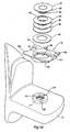
- Fig 1 shows a pivot assembly 10 that is used to connect a mirror head 11 to a mirror mounting or vehicle bracket 12.
- the vehicle bracket 12 is secured to a motor vehicle, and the pivot assembly 10 is used to connect the mirror head 11 securely in its deployed or operative position while at the same time allowing the mirror head to rotate with respect to the vehicle bracket 12. This enables the mirror head 11 to be manually moved to a parked position, or to "break away” if it is impacted or hit either while the vehicle is moving or stationery.
- the pivot assembly 10 comprises a first and second plate which in this embodiment comprise bracket plate 13 which is attached to the vehicle bracket 12 and a case plate 14 which is rotatably mounted to the bracket plate 13.
- the case plate 14 is in turn attached to the mirror head 11.
- a spigot 17 projects away from the bracket plate 13 shown also in Fig 3.
- the bracket plate 13 is a pressed metal component with the spigot being formed as part of the pressing operation.
- the spigot 17 has an upper surface 18, a cylindrical wall forming a bearing surface 19 and an aperture 20.
- the case plate 14 shown in Fig 4 is also a pressed metal component. It comprises a substantially planar plate or upper plate 24 with a centrally located depression 21.
- the depression 21 comprises a circular flange 22, a wall 23 surrounding the flange 22.
- a bearing surface 25 defines an aperture 26 within the circular flange 22.
- the thickness of the circular flange 22 in this embodiment is less than the height of the bearing surface 19 on the spigot 17 and the aperture 26 is journalled for rotation around the bearing surface 19 of the spigot 17. It may be that, in normal operation, that there is no contact between bearing surfaces 19 and 25 and that a clearance is maintained. However, even in this example, in certain load conditions there will be contact between bearing surfaces 19 and 25.
- the bracket plate 13 has a support surface 28 which extends around the base of the spigot 17.
- the support surface 28 is engaged by the lower surface of the flange 22.
- the extent of the surface area of the flange 22 engaging with the support surface 28 provides a stable connection between the bracket plate 13 and the case plate 14. This prevents rocking movement between the mirror head 11 and vehicle bracket 12 in normal use.
- Detents are provided between the bracket and case plates 13 and 14. These detents are used to hold the case plate 14 in a predetermined position with respect to the bracket plate 13.
- the detents comprise a number of notches that are formed on the intersection between the bearing surfaces 19 and 25, and detent elements, which in this embodiment comprise steel balls that are located within the notches. The detent elements are held in place to prevent relative rotation and to lock the detent until the detent elements are disengaged from one of the two aligned notches.
- radially spaced recesses comprising notches 29 and 30 are formed in the edge of the aperture 26 and the spigot 17 respectively.
- the notch 30 (see Fig 5) is a v-shaped notch further comprising a pair of angled surfaces 31 and 32. There are three pairs of such notches 29 and 30 which are spaced around the spigot 17. The pair of angled surfaces 31 and 32 result in a v-shaped notch in plan view that has decreasing depth from the periphery of the flange 22 to the inner cusp 33.
- the notch 29 comprises a pair of side walls 34 and a sloped rear wall 35.
- the detent elements comprise steel balls 36.
- the diameter of the steel ball is such that it abuts against the angled surface of 31 and 32 of notch 30 and the side walls 34 of notch 29.
- the side walls 34 are angled so that the opening of notch 29 is wider than the rear wall 35. This ensures that the steel ball 36 will abut against the side walls 34 and enables a clearance to be maintained between the steel balls 36 and the rear wall 35.
- a downward force is applied to the steel balls 36, then the case plate 14 is restrained with respect to the spigot 17.
- the angled surfaces 31 and 32 will apply force to the ball 36 which will be resisted by the opposite side wall 34. Because of the difference in angles between the respective surface 30 or 31 and the side walls 34, the angled surfaces 31 and 32 will push the ball 36 into the notch 29. At the same time, the movement of the notch 30 with respect to notch 29 will cause the ball to be lifted and pushed upwardly and into notch 29 as the ball 36 disengages from the notch 30.
- the notch 29 slopes away from notch 30 which assists in the upward movement of the balls 36. Accordingly, the rear wall 35 slopes away from the notch 30 so that clearance with the steel ball 36 is maintained.
- the periphery of the flange 22 has a chamfered edge 39.
- the balls 36 When the notch 30 is moved out of alignment of the notch 29, the balls 36 will be raised so that they rest against the chamfered edge 39 and the walls 34 of the notch 29. Accordingly, the balls 36 will be in a raised position with respect to the flange 22 when the notches 29 and 30 are out of alignment, and will be at a lower level when the notches 29 and 30 are aligned.
- a spring is used to apply downward force to each of the steel balls 36 which in turn provides the necessary resistance to rotation of the case plate 14 with respect to the spigot 17.
- a pair of springs 40 are used which each comprise a concave disc with a centre aperture 42.
- the diameter of the springs 40 is approximately 36mm and the diameter of the aperture 42 is approximately 20mm.
- the thickness of the material used to produce the spring 40 is approximately 0.3mm and is hardened carbon steel.
- the metal disc is conical in cross section with the periphery of the aperture 42 approximately 2mm higher than the outer periphery of the spring 40. This results in a concave spring 40.
- the threaded retainer 41 has a threaded shaft 43 that engages within a threaded aperture 44 within the spigot 17.
- the shaft 43 locates through the apertures 42 in the springs 40 so that the periphery of the aperture 42 abut against the end flange 45 of the retainer 41.
- a washer 46 is located on top of the spigot 17. As seen in Fig 10, the washer 46 provides a surface against which the outer periphery of the lower spring 40 abuts.
- the steel balls 36 projects slightly above the upper surface 18 of the spigot 17 even when the notches 29 and 30 align. Accordingly, the washer 46 abuts against the steel balls 36 rather than the upper surface 18 of the spigot 17.
- the threaded retainer 41 can be used to pre-load the springs 40 against the balls 36. This compression will tend to flatten out the springs 40.
- the design of the spring is such that the spring force will increase to a maximum pre-load force but this force will then decrease as the spring further flattens.
- Spring force against deflection is shown in Fig 11. The effect is a decreasing spring force as the deflection increases from the maximum pre-load position due to a negative spring rate.
- the springs 40 can be pre-loaded so that they apply the maximum force to the balls. Any further deflection of the springs 40 as the balls 36 rise will result in a reducing force being applied to the balls 36. Accordingly, maximum detent holding force will be required when the balls 36 are engaged within the aligned notches 29 and 30 and that the force applied to the balls 36 will in fact reduce as they are lifted through rotation of the case plate 14 with respect to the spigot 17.
- either angled surfaces 31 or 32 will apply force to each of the balls 36.
- the angled surfaces 31 or 32 will push the steel ball 36 into the notch 29 while at the same time lifting it upwardly. This upward movement is resisted by the springs 40, although a continued upward movement of the springs 40 results in a reduction of the spring force.
- the steel balls 36 will then progressively be easier to disengage from the notch 30. When the steel balls 36 are fully raised, they will be held between notches 29 and the chamfered edge 39.
- the steel balls 36 will remain in this raised position until the notches 29 and 30 are once again brought into alignment. Further notches 30 may be provided at intermediate positions to act as a further detents to hold a mirror in a parked position. In either case, when the notches 30 again align with the notches 29, the balls 36 will again have the maximum pre-load force applied by the springs 40 and will therefore positively hold the case plate 14 with respect to the spigot 17.
- the increased surface area contact between the flange 22 and the support surface 28 will result in reduced rocking of the mirror head 11 and the ability to contain lubricants within the depression 21 of the case plate 14.
- the extent of surface area between the flange 22 and the support surface 28 will minimise the loss of lubricants or the entry of contaminants or corrosive fluids into the case plate 14.
- Figs 6 to 8 shows steel blocks 49 which are shaped to locate both within notch 29 and 30.
- the rear end 50 has a generally rectangular cross section which locates within notch 29.
- the forward end 51 of the block 49 has a pair of angled surfaces 52 and 53 which engage the notch 30 so that the surfaces 52 and 53 abut against the surfaces 31 and 32. This provides a greater contact area by comparison to the steel balls 36.
- Fig 13 An alternative for the first embodiment is shown in Fig 13.
- the spigot 17 is part of the vehicle bracket 12. This can be achieved either by a diecast or moulded insert for the bracket 12, or securing the spigot 17 to the bracket 12 via a threaded fastening, a bayonet fitting, or threaded fasteners.
- the case plate 14 secures to the mirror head 11 in the same manner as described in the first embodiment.
- the pivot functions in exactly the same way as that described in the first embodiment.
- case plate 14 part of the mirror head 11 in addition to incorporating the spigot 17 into the bracket 12.
- case plate 14 may be incorporated into the mirror head 11 while using a bracket plate 13 similar to that shown in Figs 2 and 3.
- the pivot assembly 55 comprises a spigot 56 and a plate 57.
- the plate 57 has an aperture 59 which locates around the spigot 56.
- the aperture 59 is formed in the centre of a raised circular ridge 60 which is formed by a pressing operation into plate 57.
- the pressing operation forms the aperture 59, a chamfered edge 61, a plurality of v-shaped notches 62 and a circular bearing surface 63 on the underneath surface of the ridge 60 (see Fig 14a).
- the spigot 56 is provided with a circular flange 65 which locates within the recess formed by the ridge 60 on the underneath surface of the plate 57.
- the circular flange 65 abuts against the circular bearing surface 63 on the underneath surface of the ridge 60 and the depth of the recess formed by the ridge 60 is to ensure that the base of the spigot 56 and the circular flange 65 do not project below a surface of the plate 57.
- the spigot 56 and circular flange 65 is also formed from a pressed metal component.
- the spigot 56 has three notches 67 pressed into its periphery. Notches 67 align with three of the v-shaped notches 62.
- the detents comprise steel balls 68 in combination with the v-shaped notches 62 and notches 67.
- the steel balls 68 locate between the aligned v-shaped notch 62 and notch 67 and, in conjunction with force applied by springs, hold the plate 57 with respect to the spigots 56.
- the balls 68 project slightly above the upper surface 69 of the spigot 56 when in place between adjacent notches 62 and 67. This enables a washer 70 to locate above the upper surface 69 of the spigot 56 and bear against the steel balls 68.
- a bush 71 is used to align the washer 70 together with three springs 72.
- the washer 70 and springs 72 have a central aperture 73 which each locate around the bush 71.
- the bush 71 sits on a circular depression 74 within the upper surface 69 of the spigot 56.
- a cap 75 covers the assembly of the springs 72 and washer 70.
- the upper surface 76 of the bush 71 abuts against the inside surface of the cap 75.
- the aperture 77 in the cap 75 is the same diameter of the internal diameter of the bush 71.
- the whole assembly 55 is held together by a bolt 78 and a nut 79.
- the longitudinal height of the bush 71 ensures that tightening of the bolt 78 will result in the cap 75 compressing the springs 72 and applying a pre-load.
- the springs 72 in this embodiment are the same as the springs 40 described in the previous embodiment.
- the degree of compression of the springs 72 again provides a pre-load force which is applied via the washer 70 to the balls 68.
- each of the v-shaped notches 62 comprise a pair of angled surfaces 81 and 82.
- the notches 67 have a generally circular cross-section so that when the plate 57 is rotated with respect to the spigot 57, the angled surfaces 81 and 82 tend to lift the steel balls 68 upwardly within the notches 67.
- the steel balls 68 remain within the notches 67 and are lifted against the washer 70 and springs 72 as the v-shaped notch 62 moves out of alignment with the notch 67. The ball is then held between the notches 67 and the chamfered edge 61.
- the springs 72 are pre-loaded to a point where further compression of the springs result in a reducing spring force. This means that maximum force is applied to the steel balls 68 when the notches 62 and 67 are aligned. This then results in the maximum holding force between the plate 57 and the spigot 56.
- the six v-shaped notches 62 are provided around the aperture 59. This provides three detent positions. The first is the in-use position, with two detent positions provided for when the mirror is pushed forward and rearwardly. The angular spacing between the v-shaped notches 62 varies depending on the required extent of forward and rearward movement.
- the plate 57 is designed to be located within a tubular arm which extends between a mirror head and a mounting bracket.
- the plate 57 is provided with curved sides 83 which act to locate the plate 57 within the tubular arm.
- the spigot 56 is secured to the mirror bracket by the bolt and nut 78 and 79.
- Figs 15 and 16 illustrate a third embodiment of the invention.
- This embodiment comprises a first plate 85 and a second plate 86.
- Each of the plates have a central aperture 87 through which a shaft 88 locates.
- the shaft 88 allows the first and second plates 85 and 86 to rotate with respect to one another and allows some relative longitudinal movement between the plates 85 and 86.
- the plates 85 and 86 in this embodiment are pressed metal, and detents are formed between the first and second plate 85 and 86 that comprise v-shaped recesses 90 and v-shaped projections 91.
- the v-shaped recesses 90 are formed in a raised annular ridge 92 which is pressed outwardly from one side of the plate 85.
- Each of the v-shaped projections 91 are pressed outwardly from one side of the plate 86.
- Each v-shaped recess and projection is radially spaced around the centre of the apertures 87 so that rotation of one of the plates 85 or 86 with respect to the shaft 88 will result in movement of the projections 91 into and out of the recesses 90.
- Each of the recesses and projections comprise a pair of angled surfaces 93 and 94 which slide with respect to one another and therefore cause the plates 85 and 86 to separate with respect to one another.
- These angled surfaces 93 and 94 provide a mechanical advantage to overcome the spring force which forces the plates 85 and 86 together.
- a spring 95 comprises a concave disc with a centre aperture 96.
- the shaft 88 locates through the aperture 96.
- the shaft 88 includes a flange 97 which holds the spring 95 captive against the plate 85.
- To secure the shaft 88 its end 99 is rolled over the circular edge 98 of the aperture 87 in plate 86. The required pre-load is applied on the spring 95 before the rolling operation.
- Both the first and third embodiment connect in similar manner to the mirror head 11 and vehicle bracket 12.
- the bracket plate 13 has tabs 101 that project from the bracket plate 13 and are in a plane slightly below the bracket plate 13.
- the vehicle bracket 12 has apertures 102 within which the tabs 101 locate.
- the bracket plate 13 is then pushed in a direction to enable the tabs 101 to engage slots 103 that are located within the recesses 102. This holds the bracket plate 13 against the vehicle bracket 12.
- Locking tabs 105 are formed in the bracket plate 13.
- a cut 106 extends along the edge of the plate which then enables that edge to be deflected downwardly to form the locking tab 105.
- the vehicle bracket 12 has corresponding depressions 107 which are engaged by the ends 108 of the locking tabs 105 once the bracket plate 13 is pushed to a position where the tabs 101 are fully engaged.
- a locking tab 105 engaging a recess 107 is shown in Fig 9 where the ends 108 of the locking tabs 105 abut against the end of the recesses 107 and thereby hold the bracket plate 13 in position on the vehicle bracket 12.
- the case plate 14 has similar tabs 101 that engage corresponding slots within the mirror head 11. Again, locking tabs 105 engage recesses within the mirror head which hold the case plate 14 in place.
- a similar attachment means is used in the third embodiment. Again, the tabs 101 that engage corresponding slots in the vehicle bracket 12 and mirror head 11 and there are provided locking tabs 105 that engage recesses in the mirror head 11 and vehicle bracket 12 to hold the first and second plate 85 and 86 in place.
- Both of the attachment means for the first and third embodiments make it very easy to secure the pivot assembly 10 and 84 between a vehicle bracket 12 and mirror head 11.
- the pivot assemblies 10 and 84 are a module which enable easy connection of the mirror head 11 to a vehicle bracket 12.
- threaded fasteners 109 may be used to secure the case plate 14 and bracket plate 13 to the mirror head 11 and vehicle bracket 12.
- the pivot assembly 110 incorporates an electric motor drive which can be used to either fold the mirror to a parked position when required, or provides motorised mirror adjustment about one axis only.
- This type of mirror is know as a mono-axis mirror.
- it is often required to bring the outermost portion of the wing mirror as close as possible to the vehicle body when the vehicle is parked. This minimises the potential for impact to the wing mirror.
- the mirror In the case of a mono-axis mirror, the mirror is designed to do away with the conventional two axis mirror plane adjustment mechanism which normally comprises two independent motors. Instead, the mirror is designed so that adjustment about a horizontal axis is not required. Therefore, the mirror is provided with a single axis adjustment about a substantially vertical axis.
- the pivot assembly 110 comprises a bracket plate 113 and a case plate 114.
- the attachment of the bracket plate and case plate 113 and 114 to the mirror head 11 and vehicle bracket 12 is similar to the method used in the first and third embodiments although not illustrated in Figs 18 and 19.
- the bracket plate 113 is provided with a spigot 117 to which the case plate 114 is journalled for rotation.
- the case plate 114 has a flange 142 within which an aperture 126 is formed.
- the aperture 126 is defined by a bearing surface 125.
- the aperture 126 enables the flange 142 to locate around the spigot 117.
- a number of components are provided which will enable the case plate 114 to be driven electrically around the spigot 117, a spring means which will provide the necessary download force to hold the case plate securely with respect to the bracket plate 113 and an override clutch which will enable the mirror head 11 to break away if impacted or manually moved.
- the assembly shown in Fig 19 comprises a friction washer 144 and bush washer 146 which first locates over the spigot 117.
- This friction washer 144 locates between the flange 142 and the support surface 128. In this embodiment, there is contact between the aperture 125 and the spigot 117.
- the bush washer 146 minimises rotational friction.
- a further friction washer 144 which locates between a spacer washer 145 and the upper surface of the flange 142.
- a further friction washer 144 is positioned on the upper surface of the spacer washer 145.
- a clutch ring 148 which engages with a gear wheel 149.
- the gear wheel 149 is driven by a worm drive 150 which is in turn driven by an electric motor 151.
- the clutch ring 148 is fixed with respect to the spigot 117. In this embodiment, this is achieved by a. press fit, but splines may also be used.
- the press fit enables the clutch ring 148 to be fixed to the spigot 117 while at the same time ensuring the required clearance with respect to the friction washers 144, flange 142 and spacer washer 145. It allows for the clearance between these components to be controlled so that there is no excessive free-play between the bracket plate 113 and the case plate 114.
- Figs 18 and 19 show the spring 136 which comprises the same concave spring disc used in the previous embodiments.
- the spring 136 is held between a spigot washer 137 and a load distribution washer 138.
- Detents are provided between the clutch ring 148 and gear wheel 149 which allow for manual breakaway of the mechanism. As will be described below, the detents used in this forth embodiment are substantially the same as described in the previous embodiments.
- the friction washers 144 are chosen depending on the application. In the case of a mono-axis mirror, the friction washers 144 are designed to provide sufficient friction to movement to restrain unwanted movement of the mirror head 11 when in its deployed position. Due to backlash within the worm drive 150 and gear wheel 149, there will be some potential for the mirror head 11 to move within the extent of this backlash. However, the friction resulting from the three friction washers 144 is high enough so that movement of the mirror head 11 within this backlash will not occur. Accordingly, the friction washers 144 are selected to provide stable location of the mirror head 11. In the case of parking the mirror head 11, the friction washers 144 are chosen so that they lower the friction forces.
- electric motor 151 needs to be powerful enough to overcome the friction force provided by the friction washers 144. Provided that sufficient drive force is provided, the mirror head 11 and case plate 114 can be made to rotate around the spigot 117 provided that the disengagement force of the detents is greater than the force required to rotate the case plate 114. This prevents the detents from disengaging while the electric motor 151 is driving the case plate 114 around the spigot 117.
- the electric motor 151 and worm drive 150 are secured with respect to the case plate 114. Accordingly, as the gear wheel 149 is held stationary with respect to the spigot 117, operation of the worm drive 150 will cause it, and any components to which it is attached, to be driven around the gear wheel 149 and spigot 117.
- the electric motor 151 can be fitted with conventional sensors to determine current overload which can be used to automatically de-energise the electric motor 151. Accordingly, if stops are encountered by either the mirror head 11 or case plate 114, current rises will occur which can then be used to cease mirror head 11 movement.
- both the clutch ring 148 and the gear wheel 149 are provided with aligned v-shaped notches 129 and 130 which are similar to those described for the previous embodiments.
- steel balls 134 also locate within the aligned notches 129 and 130. The notches 130 are designed to move the steel balls 134 into notches 129 while at the same time lifting the steel balls vertically against the washer 138.
- the spring 136 has a negative spring rate after being pre-loaded so that the load applied to the steel balls 134 decreases as each of the steel balls 134 move into the notch 129. This in turn reduces the resistance to rotation provided by each of the friction washers 144.
- the electric motor 151 is designed so that it can adopt a number of positions around the gear wheel 149.
- the orientation of the electric motor 151 can range from flat and in line with the general plane of the pivot 10 to an acute angle between the pivot 110 and the motor 151. This will enable the pivot assembly 110 and motor 151 to be adjusted so that it can locate conveniently within a number of mirror head designs.
Landscapes
- Engineering & Computer Science (AREA)
- Multimedia (AREA)
- Mechanical Engineering (AREA)
- Rear-View Mirror Devices That Are Mounted On The Exterior Of The Vehicle (AREA)
Abstract
Description
- This invention relates to a pivot assembly incorporating a detent that is used to connect a mirror head and mirror mounting bracket of a rear vision mirror. In particular, it relates to a pivot assembly having attachment means which enables it to be secured between a mirror head and mirror mounting bracket.
- Vehicle mirrors, in particularly external side rear view mirrors normally comprise a mirror head which is pivotally attached to a mounting bracket. The mounting bracket is in turn secured to the motor vehicle body. The pivot enables the mirror head to rotate with respect to the bracket to either allow movement of the mirror head if it is impacted either while the vehicle is moving or stationery (referred to as "mirror break away") or to move to a parked position under the action of drive means incorporate the mirror head to ensure that the mirror head is moved to position where it is as dose to the vehicle body as possible.
- A detent is normally used in the pivot. This provides a positive location and holding force for the mirror in various positions as it is rotated about the pivot. The detents resist initial movement of the pivot and require a minimum force in order to overcome the detent force.
- Such detents are common practice in the field, and normally comprise either circular balls held between a surface of the mirror head and mounting bracket which locate within recesses or abutting ramped surfaces. The holding force is provided by a spring which is normally a coil spring located around a vertical spigot. The spigot is normally incorporated into the mounting bracket and the mirror head has an aperture which locates over the spigot. One disadvantage of this is the fact that the spigot on the bracket and the aperture within the mirror head tend to position the mirror further outward than might be desirable. This imposes certain limitations of the design of the mirror head which impact on its stability and ability to resist vertical loads. It also means the use of more robust materials such as die-cast components which are more expensive, and increases the amount of material required to manufacture the mirror.
- The aim of the invention is to design a new style of pivot connection between a mirror head and mirror mounting bracket and to also address the problems referred to above.
- In its broadest form, the invention is a pivot assembly connecting the mirror head and mirror mounting bracket of a rear vision mirror comprising;
- a spigot,
- a plate,
- an aperture in said plate journalled to said spigot,
- a detent between said plate and spigot that changes from a locked position, where said plate is held with respect to said spigot, to a disengaged position by rotation of said plate with respect to said spigot,
- a spring acting against said detent to hold it in said locked position, said spring yielding to allow said detent to move to a disengaged position as said plate is rotated with respect to said spigot, and
- attachment means on both said spigot and plate that allow said spigot to be secured to either one of said mirror head or said mirror mounting bracket and said plate to be secured to either one of said mirror head or said mirror mounting bracket to enable said mirror head to be held, or rotated with respect to said mirror mounting bracket.
-
- One main advantage of the pivot assembly is its modular nature which enables a standard design of pivot assembly to be utilised between any mirror head and mounting bracket. All that is required is to standardise the area of the mirror head and mounting bracket between which the pivot assembly locates.
- The invention also enables the pivot assembly to have a relatively small height by comparison to existing spigots. This in turn allows the glass of the mirror head to be placed further inboard and over the mirror mounting bracket which is not possible with existing spigot designs. This in turn reduces the moment arm of the mirror arm and decreases the amount of material required for manufacture of the mirror head.
- There may be several means of attaching the pivot assembly to the rear vision mirror. In one instance, the pivot assembly may have a first and second plate which are spaced and parallel with one plate located above the other and attached to the mirror head, the lower plate being attached to the mirror mounting bracket. Alternatively, the invention may comprise a spigot and plate where the spigot is attachable either to the mirror head or the mounting bracket. For example, in the case of a mirror head that may be supported by one or more arms to the mounting bracket, the pivot assembly can be located within the arm with a vertical pin or bolt securing the spigot with respect to the mounting bracket.
- A number of attachment means may be used to secure the pivot assembly between the mirror head and mounting bracket. These may include threaded fasteners which locate through plate elements and engage corresponding surfaces within the mirror head or mounting bracket or they may include pins or bolts which locate through the centre of the spigot to thereby secure the spigot with respect to either of the components.
- In addition, the attachment means may comprise elements which enable quick and easy attachment of the pivot assembly to the various components. For example, tabs or other projections which can locate into the apertures and be slid into position so that the tabs hold the pivot assembly with respect to the mirror head or mounting bracket. Non-return catches can be used to hold the pivot assembly in place and to prevent disengagement of the tabs from their apertures.
- A variety of detents can be used. These may incorporated indentations and projections formed within first and second plates, or may also comprise detent elements which are held in recesses or notches between the rotating components. In both cases, the detents are held in their engaged or locked positions by a spring which can yield sufficiently to enable disengagement of the detents.
- Preferably, the spring comprises a concave disc which may also have a negative spring rate as it yields during disengagement of the detent. A concave disc will have a positive spring rate which changes to a negative spring rate as it is flexed towards a flattened position. This is an inherent property of such a design, and the degree of pre-tension load can be varied by changing material, material thickness, the degree of concavity, and the number of concave spring plates which are stacked together.
- The use of a spring having a negative spring rate is that maximum force is applied to the detent at its pre-loaded position and that upon force being applied to the spring, the load applied to the detent reduces so that the force or torque required to rotate the mirror head also reduces. This provides maximum holding force while at the same time reducing the force required to rotate the mirror head once this holding force has been overcome.
- An advantage of the use of the spring in the form of a concave disc is the significant reduction in height requirement by comparison to conventional coil springs. This in turn means that the pivot requires less vertical space thereby enabling the mirror to be positioned more inboard and over the mirror mounting bracket than otherwise possible. Accordingly, the concave disc spring will also have application in existing mirror pivot designs.
- Various components of the pivot assembly are preferably produced from stamped metal components. However, other manufacturing processes such as casting, sintering or machining may also be used.
- Further, the invention may also comprise a drive means which can be used to rotate the mirror head to the parked position. In this case, the detent acts as an override clutch which enables the mirror head to rotate should the mirror be subject to a break-away force or become jammed while being rotated to a parked position. This will prevent gears used in the drive means from stripping when break away or jamming of the mirror head occurs.
- In order to fully understand the invention, the preferred embodiments will now be described. However, it should be realised that the invention is not to be confined or restricted to the details of these embodiments.
- The embodiments will be illustrated in the accompanying figures in which;
- Fig 1 is an exploded perspective view of a mirror head, mirror mounting bracket and a pivot assembly,
- Fig 2 is an exploded view of a pivot assembly and a mirror mounting bracket according to a first embodiment,
- Fig 3 is a plan view of a bracket plate of the first embodiment,
- Fig 4 is a plan view of a case plate of the first embodiment,
- Fig 5 shows a segmented view of the wall and flange of the case plate shown in Fig 4,
- Fig 6 is a part exploded view of a pivot assembly of the first embodiment,
- Figs 7 & 8 show perspective views of the detent elements shown in Fig 6,
- Fig 9 shows a part section view of a locking tab of the first and third embodiments engaged in a depression,
- Fig 10 shows a cross-sectional assembled view of springs, washer and detent elements used in the first and second embodiment,
- Fig 11 is a graph that plots the spring force against displacement of the springs used in all the embodiments,
- Fig 12 shows an exploded view of a pivot assembly and a mirror mounting bracket according to the first embodiment showing an alternative attachment method,
- Fig 13 shows an exploded view of a pivot assembly and a mirror mounting bracket according to the first embodiment showing the spigot as part of the mirror mounting bracket,
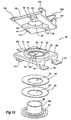
- Fig 14 shows an exploded view of a pivot assembly according to a second embodiment,
- Fig 14a shows a part cross-section view of the spigot flange, ridge in the plate and bearing surface on the underside of the ridge,
- Fig 15 shows an exploded view of a pivot assembly according to a third embodiment,
- Fig 16 shows a cross-sectional view of a pivot assembly illustrated in Fig 15,
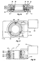
- Fig 17 shows a plan view of a pivot assembly having an electric motor for rotating the pivot according to a forth embodiment,
- Fig 18 is a cross-section of Fig 17, and
- Fig 19 is an exploded view of the pivot assembly of Figs 18 and 19.
-
- Fig 1 shows a
pivot assembly 10 that is used to connect amirror head 11 to a mirror mounting orvehicle bracket 12. Thevehicle bracket 12 is secured to a motor vehicle, and thepivot assembly 10 is used to connect themirror head 11 securely in its deployed or operative position while at the same time allowing the mirror head to rotate with respect to thevehicle bracket 12. This enables themirror head 11 to be manually moved to a parked position, or to "break away" if it is impacted or hit either while the vehicle is moving or stationery. - Referring to Fig 2, the
pivot assembly 10 comprises a first and second plate which in this embodiment comprisebracket plate 13 which is attached to thevehicle bracket 12 and acase plate 14 which is rotatably mounted to thebracket plate 13. Thecase plate 14 is in turn attached to themirror head 11. - A
spigot 17 projects away from thebracket plate 13 shown also in Fig 3. In this embodiment, thebracket plate 13 is a pressed metal component with the spigot being formed as part of the pressing operation. Thespigot 17 has anupper surface 18, a cylindrical wall forming a bearingsurface 19 and anaperture 20. - The
case plate 14 shown in Fig 4 is also a pressed metal component. It comprises a substantially planar plate orupper plate 24 with a centrally locateddepression 21. Thedepression 21 comprises acircular flange 22, awall 23 surrounding theflange 22. A bearingsurface 25 defines anaperture 26 within thecircular flange 22. The thickness of thecircular flange 22 in this embodiment is less than the height of the bearingsurface 19 on thespigot 17 and theaperture 26 is journalled for rotation around the bearingsurface 19 of thespigot 17. It may be that, in normal operation, that there is no contact between bearingsurfaces surfaces - The
bracket plate 13 has asupport surface 28 which extends around the base of thespigot 17. Thesupport surface 28 is engaged by the lower surface of theflange 22. The extent of the surface area of theflange 22 engaging with thesupport surface 28 provides a stable connection between thebracket plate 13 and thecase plate 14. This prevents rocking movement between themirror head 11 andvehicle bracket 12 in normal use. - Detents are provided between the bracket and
case plates case plate 14 in a predetermined position with respect to thebracket plate 13. In this embodiment, the detents comprise a number of notches that are formed on the intersection between the bearing surfaces 19 and 25, and detent elements, which in this embodiment comprise steel balls that are located within the notches. The detent elements are held in place to prevent relative rotation and to lock the detent until the detent elements are disengaged from one of the two aligned notches. - Referring to Fig 2, radially spaced
recesses comprising notches aperture 26 and thespigot 17 respectively. In this embodiment, the notch 30 (see Fig 5) is a v-shaped notch further comprising a pair ofangled surfaces such notches spigot 17. The pair ofangled surfaces flange 22 to theinner cusp 33. - The
notch 29 comprises a pair ofside walls 34 and a slopedrear wall 35. - The detent elements comprise
steel balls 36. When thenotches notch 30 and theside walls 34 ofnotch 29. Theside walls 34 are angled so that the opening ofnotch 29 is wider than therear wall 35. This ensures that thesteel ball 36 will abut against theside walls 34 and enables a clearance to be maintained between thesteel balls 36 and therear wall 35. Provided that a downward force is applied to thesteel balls 36, then thecase plate 14 is restrained with respect to thespigot 17. - When sufficient rotation forces is applied to the
case plate 14, theangled surfaces ball 36 which will be resisted by theopposite side wall 34. Because of the difference in angles between therespective surface side walls 34, theangled surfaces ball 36 into thenotch 29. At the same time, the movement of thenotch 30 with respect to notch 29 will cause the ball to be lifted and pushed upwardly and intonotch 29 as theball 36 disengages from thenotch 30. Thenotch 29 slopes away fromnotch 30 which assists in the upward movement of theballs 36. Accordingly, therear wall 35 slopes away from thenotch 30 so that clearance with thesteel ball 36 is maintained. - The periphery of the
flange 22 has a chamferededge 39. When thenotch 30 is moved out of alignment of thenotch 29, theballs 36 will be raised so that they rest against the chamferededge 39 and thewalls 34 of thenotch 29. Accordingly, theballs 36 will be in a raised position with respect to theflange 22 when thenotches notches - A spring is used to apply downward force to each of the
steel balls 36 which in turn provides the necessary resistance to rotation of thecase plate 14 with respect to thespigot 17. In this embodiment, a pair ofsprings 40 are used which each comprise a concave disc with acentre aperture 42. In this embodiment, the diameter of thesprings 40 is approximately 36mm and the diameter of theaperture 42 is approximately 20mm. The thickness of the material used to produce thespring 40 is approximately 0.3mm and is hardened carbon steel. The metal disc is conical in cross section with the periphery of theaperture 42 approximately 2mm higher than the outer periphery of thespring 40. This results in aconcave spring 40. - The threaded
retainer 41 has a threadedshaft 43 that engages within a threadedaperture 44 within thespigot 17. Theshaft 43 locates through theapertures 42 in thesprings 40 so that the periphery of theaperture 42 abut against theend flange 45 of theretainer 41. - A
washer 46 is located on top of thespigot 17. As seen in Fig 10, thewasher 46 provides a surface against which the outer periphery of thelower spring 40 abuts. Thesteel balls 36 projects slightly above theupper surface 18 of thespigot 17 even when thenotches washer 46 abuts against thesteel balls 36 rather than theupper surface 18 of thespigot 17. - The threaded
retainer 41 can be used to pre-load thesprings 40 against theballs 36. This compression will tend to flatten out thesprings 40. The design of the spring is such that the spring force will increase to a maximum pre-load force but this force will then decrease as the spring further flattens. Spring force against deflection is shown in Fig 11. The effect is a decreasing spring force as the deflection increases from the maximum pre-load position due to a negative spring rate. - Accordingly, the
springs 40 can be pre-loaded so that they apply the maximum force to the balls. Any further deflection of thesprings 40 as theballs 36 rise will result in a reducing force being applied to theballs 36. Accordingly, maximum detent holding force will be required when theballs 36 are engaged within the alignednotches balls 36 will in fact reduce as they are lifted through rotation of thecase plate 14 with respect to thespigot 17. - Upon a rotational force being applied to the
case plate 14 via themirror head 11, then, depending on the direction of rotation, eitherangled surfaces balls 36. The angled surfaces 31 or 32 will push thesteel ball 36 into thenotch 29 while at the same time lifting it upwardly. This upward movement is resisted by thesprings 40, although a continued upward movement of thesprings 40 results in a reduction of the spring force. Once the required initial torque is applied to themirror head 11, thesteel balls 36 will then progressively be easier to disengage from thenotch 30. When thesteel balls 36 are fully raised, they will be held betweennotches 29 and the chamferededge 39. - The
steel balls 36 will remain in this raised position until thenotches Further notches 30 may be provided at intermediate positions to act as a further detents to hold a mirror in a parked position. In either case, when thenotches 30 again align with thenotches 29, theballs 36 will again have the maximum pre-load force applied by thesprings 40 and will therefore positively hold thecase plate 14 with respect to thespigot 17. - The use of the free floating ball bearings which self-centre within the aligned
notches notches case plates - The increased surface area contact between the
flange 22 and thesupport surface 28 will result in reduced rocking of themirror head 11 and the ability to contain lubricants within thedepression 21 of thecase plate 14. The extent of surface area between theflange 22 and thesupport surface 28 will minimise the loss of lubricants or the entry of contaminants or corrosive fluids into thecase plate 14. - As an alternative to the
detent balls 36, Figs 6 to 8 shows steel blocks 49 which are shaped to locate both withinnotch rear end 50 has a generally rectangular cross section which locates withinnotch 29. Theforward end 51 of theblock 49 has a pair ofangled surfaces notch 30 so that thesurfaces surfaces steel balls 36. - The rest of the assembly shown in Fig 6 is the same as that shown in Fig 2. A
washer 46 locates on top of theblocks 49 and thesprings 40 held against thewasher 46 by a threadedretainer 41. Rotation of thecase plate 14 with respect to thespigot 17 tends to rock theforward end 51 of theblocks 49 upwardly and this movement is initially resisted by thesprings 40. - An alternative for the first embodiment is shown in Fig 13. In this embodiment, the
spigot 17 is part of thevehicle bracket 12. This can be achieved either by a diecast or moulded insert for thebracket 12, or securing thespigot 17 to thebracket 12 via a threaded fastening, a bayonet fitting, or threaded fasteners. Thecase plate 14 secures to themirror head 11 in the same manner as described in the first embodiment. The pivot functions in exactly the same way as that described in the first embodiment. - Another variation that would be possible would be to make the
case plate 14 part of themirror head 11 in addition to incorporating thespigot 17 into thebracket 12. Alternatively, thecase plate 14 may be incorporated into themirror head 11 while using abracket plate 13 similar to that shown in Figs 2 and 3. - A second embodiment is shown in Fig 14. In this embodiment, the
pivot assembly 55 comprises aspigot 56 and aplate 57. Theplate 57 has anaperture 59 which locates around thespigot 56. Theaperture 59 is formed in the centre of a raisedcircular ridge 60 which is formed by a pressing operation intoplate 57. The pressing operation forms theaperture 59, a chamferededge 61, a plurality of v-shapednotches 62 and acircular bearing surface 63 on the underneath surface of the ridge 60 (see Fig 14a). Thespigot 56 is provided with acircular flange 65 which locates within the recess formed by theridge 60 on the underneath surface of theplate 57. Thecircular flange 65 abuts against thecircular bearing surface 63 on the underneath surface of theridge 60 and the depth of the recess formed by theridge 60 is to ensure that the base of thespigot 56 and thecircular flange 65 do not project below a surface of theplate 57. - The
spigot 56 andcircular flange 65 is also formed from a pressed metal component. Thespigot 56 has threenotches 67 pressed into its periphery.Notches 67 align with three of the v-shapednotches 62. - The detents comprise
steel balls 68 in combination with the v-shapednotches 62 andnotches 67. As with the first embodiment, thesteel balls 68 locate between the aligned v-shapednotch 62 and notch 67 and, in conjunction with force applied by springs, hold theplate 57 with respect to thespigots 56. - The
balls 68 project slightly above theupper surface 69 of thespigot 56 when in place betweenadjacent notches washer 70 to locate above theupper surface 69 of thespigot 56 and bear against thesteel balls 68. Abush 71 is used to align thewasher 70 together with threesprings 72. Thewasher 70 and springs 72 have acentral aperture 73 which each locate around thebush 71. Thebush 71 sits on acircular depression 74 within theupper surface 69 of thespigot 56. A cap 75 covers the assembly of thesprings 72 andwasher 70. Theupper surface 76 of thebush 71 abuts against the inside surface of the cap 75. Theaperture 77 in the cap 75 is the same diameter of the internal diameter of thebush 71. - The
whole assembly 55 is held together by abolt 78 and anut 79. The longitudinal height of thebush 71 ensures that tightening of thebolt 78 will result in the cap 75 compressing thesprings 72 and applying a pre-load. Thesprings 72 in this embodiment are the same as thesprings 40 described in the previous embodiment. The degree of compression of thesprings 72 again provides a pre-load force which is applied via thewasher 70 to theballs 68. - As with the previous embodiment, each of the v-shaped
notches 62 comprise a pair ofangled surfaces notches 67 have a generally circular cross-section so that when theplate 57 is rotated with respect to thespigot 57, theangled surfaces steel balls 68 upwardly within thenotches 67. Thesteel balls 68 remain within thenotches 67 and are lifted against thewasher 70 and springs 72 as the v-shapednotch 62 moves out of alignment with thenotch 67. The ball is then held between thenotches 67 and the chamferededge 61. - As is the case with the first embodiment, the
springs 72 are pre-loaded to a point where further compression of the springs result in a reducing spring force. This means that maximum force is applied to thesteel balls 68 when thenotches plate 57 and thespigot 56. - In this embodiment, the six v-shaped
notches 62 are provided around theaperture 59. This provides three detent positions. The first is the in-use position, with two detent positions provided for when the mirror is pushed forward and rearwardly. The angular spacing between the v-shapednotches 62 varies depending on the required extent of forward and rearward movement. - In this embodiment, the
plate 57 is designed to be located within a tubular arm which extends between a mirror head and a mounting bracket. Theplate 57 is provided withcurved sides 83 which act to locate theplate 57 within the tubular arm. Thespigot 56 is secured to the mirror bracket by the bolt andnut - Figs 15 and 16 illustrate a third embodiment of the invention. This embodiment comprises a
first plate 85 and asecond plate 86. Each of the plates have acentral aperture 87 through which ashaft 88 locates. Theshaft 88 allows the first andsecond plates plates plates second plate recesses 90 and v-shapedprojections 91. The v-shapedrecesses 90 are formed in a raisedannular ridge 92 which is pressed outwardly from one side of theplate 85. Each of the v-shapedprojections 91 are pressed outwardly from one side of theplate 86. Each v-shaped recess and projection is radially spaced around the centre of theapertures 87 so that rotation of one of theplates shaft 88 will result in movement of theprojections 91 into and out of therecesses 90. - Each of the recesses and projections comprise a pair of
angled surfaces plates angled surfaces plates - As with the previous embodiments, a
spring 95 comprises a concave disc with acentre aperture 96. Theshaft 88 locates through theaperture 96. Theshaft 88 includes aflange 97 which holds thespring 95 captive against theplate 85. To secure theshaft 88, itsend 99 is rolled over the circular edge 98 of theaperture 87 inplate 86. The required pre-load is applied on thespring 95 before the rolling operation. - Rotation of the
first plate 85 with respect to thesecond plate 86 results in theplates shaft 88. This separation is resisted by thespring 95. As with the previous embodiments, further deflection of thespring 95 beyond its pre-load position results in the spring force reducing thereby also reducing the force required to disengage theprojections 91 from therecesses 90. Once disengaged, theprojections 91 slide around the upper surface of theridge 92. Once theprojections 91 are bought back into alignment with therecesses 90, the spring force will again increase and clamp theplates - Both the first and third embodiment connect in similar manner to the
mirror head 11 andvehicle bracket 12. In the first embodiment, thebracket plate 13 hastabs 101 that project from thebracket plate 13 and are in a plane slightly below thebracket plate 13. Thevehicle bracket 12 hasapertures 102 within which thetabs 101 locate. Thebracket plate 13 is then pushed in a direction to enable thetabs 101 to engageslots 103 that are located within therecesses 102. This holds thebracket plate 13 against thevehicle bracket 12. - Locking
tabs 105 are formed in thebracket plate 13. Acut 106 extends along the edge of the plate which then enables that edge to be deflected downwardly to form thelocking tab 105. Thevehicle bracket 12 has correspondingdepressions 107 which are engaged by theends 108 of the lockingtabs 105 once thebracket plate 13 is pushed to a position where thetabs 101 are fully engaged. Alocking tab 105 engaging arecess 107 is shown in Fig 9 where the ends 108 of the lockingtabs 105 abut against the end of therecesses 107 and thereby hold thebracket plate 13 in position on thevehicle bracket 12. - The
case plate 14 hassimilar tabs 101 that engage corresponding slots within themirror head 11. Again, lockingtabs 105 engage recesses within the mirror head which hold thecase plate 14 in place. - A similar attachment means is used in the third embodiment. Again, the
tabs 101 that engage corresponding slots in thevehicle bracket 12 andmirror head 11 and there are provided lockingtabs 105 that engage recesses in themirror head 11 andvehicle bracket 12 to hold the first andsecond plate - Both of the attachment means for the first and third embodiments make it very easy to secure the
pivot assembly vehicle bracket 12 andmirror head 11. Thepivot assemblies mirror head 11 to avehicle bracket 12. - Alternatively, as shown in Fig 12, threaded
fasteners 109 may be used to secure thecase plate 14 andbracket plate 13 to themirror head 11 andvehicle bracket 12. - A forth embodiment of the invention is shown in Figs 18 and 19. In this embodiment, the
pivot assembly 110 incorporates an electric motor drive which can be used to either fold the mirror to a parked position when required, or provides motorised mirror adjustment about one axis only. This type of mirror is know as a mono-axis mirror. In the case of a parking mechanism, it is often required to bring the outermost portion of the wing mirror as close as possible to the vehicle body when the vehicle is parked. This minimises the potential for impact to the wing mirror. - In the case of a mono-axis mirror, the mirror is designed to do away with the conventional two axis mirror plane adjustment mechanism which normally comprises two independent motors. Instead, the mirror is designed so that adjustment about a horizontal axis is not required. Therefore, the mirror is provided with a single axis adjustment about a substantially vertical axis.
- In the embodiments shown in Figs 18 and 19, the
pivot assembly 110 comprises abracket plate 113 and acase plate 114. The attachment of the bracket plate andcase plate mirror head 11 andvehicle bracket 12 is similar to the method used in the first and third embodiments although not illustrated in Figs 18 and 19. Again, thebracket plate 113 is provided with aspigot 117 to which thecase plate 114 is journalled for rotation. Thecase plate 114 has aflange 142 within which anaperture 126 is formed. Theaperture 126 is defined by a bearingsurface 125. - The
aperture 126 enables theflange 142 to locate around thespigot 117. - A number of components are provided which will enable the
case plate 114 to be driven electrically around thespigot 117, a spring means which will provide the necessary download force to hold the case plate securely with respect to thebracket plate 113 and an override clutch which will enable themirror head 11 to break away if impacted or manually moved. - The assembly shown in Fig 19 comprises a
friction washer 144 andbush washer 146 which first locates over thespigot 117. Thisfriction washer 144 locates between theflange 142 and thesupport surface 128. In this embodiment, there is contact between theaperture 125 and thespigot 117. Thebush washer 146 minimises rotational friction. Next is afurther friction washer 144 which locates between aspacer washer 145 and the upper surface of theflange 142. Afurther friction washer 144 is positioned on the upper surface of thespacer washer 145. Next in the assembly is aclutch ring 148 which engages with agear wheel 149. Thegear wheel 149 is driven by aworm drive 150 which is in turn driven by anelectric motor 151. Theclutch ring 148 is fixed with respect to thespigot 117. In this embodiment, this is achieved by a. press fit, but splines may also be used. The press fit enables theclutch ring 148 to be fixed to thespigot 117 while at the same time ensuring the required clearance with respect to thefriction washers 144,flange 142 andspacer washer 145. It allows for the clearance between these components to be controlled so that there is no excessive free-play between thebracket plate 113 and thecase plate 114. - Figs 18 and 19 show the
spring 136 which comprises the same concave spring disc used in the previous embodiments. Thespring 136 is held between aspigot washer 137 and aload distribution washer 138. - Detents are provided between the
clutch ring 148 andgear wheel 149 which allow for manual breakaway of the mechanism. As will be described below, the detents used in this forth embodiment are substantially the same as described in the previous embodiments. - The
friction washers 144 are chosen depending on the application. In the case of a mono-axis mirror, thefriction washers 144 are designed to provide sufficient friction to movement to restrain unwanted movement of themirror head 11 when in its deployed position. Due to backlash within theworm drive 150 andgear wheel 149, there will be some potential for themirror head 11 to move within the extent of this backlash. However, the friction resulting from the threefriction washers 144 is high enough so that movement of themirror head 11 within this backlash will not occur. Accordingly, thefriction washers 144 are selected to provide stable location of themirror head 11. In the case of parking themirror head 11, thefriction washers 144 are chosen so that they lower the friction forces. - In the case of the mono-axis mirror,
electric motor 151 needs to be powerful enough to overcome the friction force provided by thefriction washers 144. Provided that sufficient drive force is provided, themirror head 11 andcase plate 114 can be made to rotate around thespigot 117 provided that the disengagement force of the detents is greater than the force required to rotate thecase plate 114. This prevents the detents from disengaging while theelectric motor 151 is driving thecase plate 114 around thespigot 117. - The
electric motor 151 andworm drive 150 are secured with respect to thecase plate 114. Accordingly, as thegear wheel 149 is held stationary with respect to thespigot 117, operation of theworm drive 150 will cause it, and any components to which it is attached, to be driven around thegear wheel 149 andspigot 117. - The
electric motor 151 can be fitted with conventional sensors to determine current overload which can be used to automatically de-energise theelectric motor 151. Accordingly, if stops are encountered by either themirror head 11 orcase plate 114, current rises will occur which can then be used to ceasemirror head 11 movement. - If the
mirror head 11 is manually rotated or is impacted, the force of rotation will be transferred via theworm drive 150 directly to thegear wheel 149. Accordingly, thegear wheel 149 will tend to rotate independently of theclutch ring 148. The upper surface of both theclutch ring 148 and thegear wheel 149 are provided with aligned v-shapednotches 129 and 130 which are similar to those described for the previous embodiments. In addition,steel balls 134 also locate within the alignednotches 129 and 130. Thenotches 130 are designed to move thesteel balls 134 into notches 129 while at the same time lifting the steel balls vertically against thewasher 138. - Accordingly, manual rotation of the
mirror head 11 will result in the detents disengaging to allow movement of themirror head 11. Operation of the detent will be exactly the same as that for the previous embodiments. - As with the previous embodiments, the
spring 136 has a negative spring rate after being pre-loaded so that the load applied to thesteel balls 134 decreases as each of thesteel balls 134 move into the notch 129. This in turn reduces the resistance to rotation provided by each of thefriction washers 144. - The
electric motor 151 is designed so that it can adopt a number of positions around thegear wheel 149. The orientation of theelectric motor 151 can range from flat and in line with the general plane of thepivot 10 to an acute angle between thepivot 110 and themotor 151. This will enable thepivot assembly 110 andmotor 151 to be adjusted so that it can locate conveniently within a number of mirror head designs.
Claims (16)
- A pivot assembly between a mirror head and a mirror mounting bracket of a rear vision mirror comprising;an aperture and a spigot received in the aperture,the spigot being on either the mirror mounting bracket or the mirror head,and the aperture being in the other of the mirror mounting bracket or the mirror head,the spigot fitting into the aperture such that the mirror head may rotate with respect to the mirror mounting bracket,a detent arrangement between the mirror mounting bracket and the mirror head that enables rotation of the mirror head with respect to the mirror mounting bracket from a locked position, where the mirror head is held in a selected position with respect to the mirror mounting bracket, to a disengaged position in which the mirror head is rotated with respect to the mirror mounting bracket, anda spring assembly adapted to apply force against the detent arrangement, the spring assembly having a negative spring rate when compressed from a pre-loaded position.
- A pivot assembly according to claim 1 wherein the spring assembly comprises at least one circular disc having a concave periphery.
- A pivot assembly according to claim 2 wherein the spring assembly further comprises an aperture in the centre of the disc and the disc having a conical cross-section in a plane containing the axis of the disc.
- A pivot assembly according to any one of the preceding claims, wherein the spring assembly has a positive spring rate for the first part of its deflection and a negative spring rate following the first part of its deflection.
- A pivot assembly according to any one of the preceding claims, wherein the spring is pre-loaded against the detent arrangement so that a maximum spring force is applied in the locked position and so that the spring force decreases during movement to the disengaged position.
- A pivot assembly according to any one of the preceding claims wherein the detent arrangement includes a plurality of first radially spaced recesses associated with the spigot, a plurality of second radially spaced recesses associated with the aperture that each align with a corresponding first recess in the spigot and a detent element located between each aligned first and second recess that engages in each aligned first and second recess to lock the detent arrangement and that moves out of one of the recesses to disengage the detent arrangement.
- A pivot assembly according to claim 6 wherein the detent elements comprise balls.
- A pivot assembly according to claim 6 or 7 wherein the aperture is associated with an aperture plate and the recesses associated with the aperture comprise v-shaped notches in the aperture plate around the periphery of the aperture.
- A pivot assembly according to claim 8 wherein the detent elements have surfaces defining a v-shaped projection that abut against the v-shaped notches.
- A pivot assembly according to claim 8 or 9 wherein each v-shaped notch comprises a pair of ramped surfaces, each of which are also at an angle with respect to the axis of the spigot.
- A pivot assembly according to claim 10 wherein the ramped surfaces cause the detent elements to move away from the v-shaped notch while remaining engaged with the recesses in the spigot.
- A pivot assembly according to any one of claims 8 to 11 wherein the aperture plate has a chamfered surface around the periphery of the aperture, the detent elements being held between the chamfer and the recesses in the spigot when the v-shaped notches are moved out of alignment from the recesses in the spigot.
- A pivot assembly according to claim 7 further comprising a washer between the balls and the spring assembly, the balls moving against the washer and the spring as the pivot assembly moves from a locked to disengaged position.
- A pivot assembly according to any one of the preceding claims further comprising a threaded fastener that connects to the spigot and that holds the spring assembly and detent arrangement to the spigot.
- A pivot assembly according to any one of claims 1 to 7 wherein the spigot is mounted on a spigot plate and the aperture is associated with an aperture plate.
- A pivot assembly according to claim 15 wherein the spigot plate is adapted to be mounted onto the mirror mounting bracket and the aperture plate is adapted to be mounted to the mirror head.
Applications Claiming Priority (3)
| Application Number | Priority Date | Filing Date | Title |
|---|---|---|---|
| AUPP853699 | 1999-02-05 | ||
| AUPP8536A AUPP853699A0 (en) | 1999-02-05 | 1999-02-05 | A pivot with a detent |
| EP00906045A EP1214225A4 (en) | 1999-02-05 | 2000-02-04 | A pivot with a detent |
Related Parent Applications (1)
| Application Number | Title | Priority Date | Filing Date |
|---|---|---|---|
| EP00906045A Division EP1214225A4 (en) | 1999-02-05 | 2000-02-04 | A pivot with a detent |
Publications (2)
| Publication Number | Publication Date |
|---|---|
| EP1225091A1 true EP1225091A1 (en) | 2002-07-24 |
| EP1225091B1 EP1225091B1 (en) | 2004-04-07 |
Family
ID=3812737
Family Applications (2)
| Application Number | Title | Priority Date | Filing Date |
|---|---|---|---|
| EP00906045A Withdrawn EP1214225A4 (en) | 1999-02-05 | 2000-02-04 | A pivot with a detent |
| EP02003887A Expired - Lifetime EP1225091B1 (en) | 1999-02-05 | 2000-02-04 | A mirror assembly comprising a disk spring loaded pivot |
Family Applications Before (1)
| Application Number | Title | Priority Date | Filing Date |
|---|---|---|---|
| EP00906045A Withdrawn EP1214225A4 (en) | 1999-02-05 | 2000-02-04 | A pivot with a detent |
Country Status (7)
| Country | Link |
|---|---|
| US (1) | US6742756B1 (en) |
| EP (2) | EP1214225A4 (en) |
| JP (2) | JP2002536228A (en) |
| KR (1) | KR20010101948A (en) |
| AU (1) | AUPP853699A0 (en) |
| DE (1) | DE60009737T2 (en) |
| WO (1) | WO2000046071A1 (en) |
Cited By (2)
| Publication number | Priority date | Publication date | Assignee | Title |
|---|---|---|---|---|
| KR100804014B1 (en) * | 2000-08-03 | 2008-02-18 | 라이터 운트 쉐페나커 게엠베하 운트 코.카게 | Automotive Rearview Mirror |
| CN113075780A (en) * | 2021-04-13 | 2021-07-06 | 中国科学院重庆绿色智能技术研究院 | Off-axis parabolic mirror assembly and using method thereof |
Families Citing this family (31)
| Publication number | Priority date | Publication date | Assignee | Title |
|---|---|---|---|---|
| AUPR381201A0 (en) * | 2001-03-19 | 2001-04-12 | Schefenacker Vision Systems Australia Pty Ltd | Improved pivot assemblies |
| JP4153308B2 (en) * | 2001-03-26 | 2008-09-24 | シェフェネイカー・ヴィジョン・システムズ・オーストラリア・プロプライアタリー・リミテッド | Vehicle exterior mirror with self-loading pivot and end stop |
| AUPS062802A0 (en) * | 2002-02-20 | 2002-03-14 | Schefenacker Vision Systems Australia Pty Ltd | Modular pivot arrangement |
| US6941618B2 (en) * | 2002-09-13 | 2005-09-13 | Samsung Electronics Co., Ltd. | Hinge device for portable wireless terminal |
| TWI300173B (en) * | 2003-06-20 | 2008-08-21 | Arima Computer Corp | Notebook computer and the rotation structure thereof |
| AU2003903772A0 (en) * | 2003-07-21 | 2003-08-07 | George Gibbens Pty Limited | Mirror mounting assembly |
| US20050125950A1 (en) * | 2003-12-10 | 2005-06-16 | Ding-Hone Su | Hinge with a rotating function |
| ATE476320T1 (en) * | 2004-02-18 | 2010-08-15 | Smr Patents Sarl | WEAR-RESISTANT BRACKET FOR FOLDING MIRRORS |
| US7303294B1 (en) * | 2004-09-14 | 2007-12-04 | Magna Donnelly Mirrors North America L.L.C. | Vehicle mirror system with reduced friction actuation and movement |
| NL1028416C2 (en) * | 2005-02-25 | 2006-09-06 | Eaton Automotive Bv | Hinge construction and exterior mirror unit, in particular for a motor vehicle. |
| US7490946B1 (en) * | 2005-10-28 | 2009-02-17 | Magna Mirrors Of America, Inc. | Main mirror with pivot connection |
| KR100663445B1 (en) * | 2005-11-30 | 2007-01-02 | 삼성전자주식회사 | Hinge device of a portable terminal |
| FR2895524B1 (en) * | 2005-12-23 | 2008-05-02 | Essilor Int | OPTICAL LENS AND METHOD USING ANGULAR INDEXING MEANS |
| US7448762B2 (en) * | 2006-09-13 | 2008-11-11 | Fu-Chu Su | Universal sideview mirror for car |
| DE102007022244B3 (en) | 2007-05-09 | 2008-12-11 | Metallwarenfabrik Wilke Gmbh & Co. Kg | vehicle mirror |
| US7735197B2 (en) * | 2007-09-14 | 2010-06-15 | Cheng Uei Precision Industry Co., Ltd. | Hinge for circumrotatory location |
| DE102008024782A1 (en) * | 2008-05-23 | 2009-12-03 | Siemens Aktiengesellschaft | Exterior mirror for vehicle, has mirror body and mirror arm, where mirror body is drivably retained in linear drive of vehicle, and toothing bodies of bosh device provided with teeth and disk spring package |
| DE102008026039B4 (en) * | 2008-05-30 | 2012-12-13 | Ficosa International Gmbh | Rearview mirror and method for mounting a rearview mirror on a motor vehicle |
| TWM350193U (en) * | 2008-06-04 | 2009-02-01 | Quanta Comp Inc | Rotary joint device, support frame and camera apparatus |
| CN101614238B (en) * | 2008-06-27 | 2013-08-21 | 鸿富锦精密工业(深圳)有限公司 | Hinge structure |
| JP5784574B2 (en) * | 2012-11-08 | 2015-09-24 | 株式会社東海理化電機製作所 | Mirror device for vehicle |
| WO2014181265A1 (en) * | 2013-05-08 | 2014-11-13 | Smr Patents S.A.R.L. | A pivot mechanism for a vehicle external rear view mirror assembly |
| US9841047B2 (en) | 2014-06-27 | 2017-12-12 | U.S. Farathane Corporation | Fastener assembly associated with a mounting surface of such as an electronic control module or battery tray, the mounting surface incorporating a flexural and three dimensional configured receiving aperture profile for reliably seating and retaining an associated mounting fastener with low insertion force in comparison to higher extraction force and with minimal loss of material |
| JP6496397B2 (en) * | 2014-08-06 | 2019-04-03 | エスエムエル・パテンツ・エス・ア・エル・エル | Pivot assembly for vehicle exterior rear observation device and pivot assembly for the pivot assembly |
| US9947244B2 (en) * | 2015-04-02 | 2018-04-17 | Humanetics Innovative Solutions, Inc. | Adjustable spine joint assembly for crash test dummy |
| EP3208152B1 (en) * | 2016-02-16 | 2019-04-10 | Magna Auteca GmbH | Folding device for an external mirror |
| US10953788B2 (en) | 2016-05-21 | 2021-03-23 | JST Performance, LLC | Method and apparatus for vehicular light fixtures |
| US11230228B2 (en) * | 2017-05-24 | 2022-01-25 | SMR Patents S.à.r.l. | Pivot detent system and rear view device therewith |
| NL2019778B1 (en) * | 2017-10-20 | 2019-04-29 | Mci Mirror Controls Int Netherlands B V | Fixing structure, in particular for an outside view unit of a motor vehicle |
| DE102018118268B4 (en) * | 2018-07-27 | 2020-07-09 | Motherson Innovations Company Limited | REVIEW REVIEW WITH LOCKING SYSTEM |
| GB201916349D0 (en) | 2019-11-11 | 2019-12-25 | Rolls Royce Plc | Bracket |
Citations (5)
| Publication number | Priority date | Publication date | Assignee | Title |
|---|---|---|---|---|
| US3730474A (en) * | 1971-05-14 | 1973-05-01 | Delbar Products | Mirror positioning device |
| DE2736329A1 (en) * | 1977-08-12 | 1979-02-22 | Ringspann Maurer Kg A | Overload coupling with diaphragm spring - has axial teeth on coaxial hub and gear parts forced out of mesh by excess torque |
| JPS60151143A (en) * | 1984-01-18 | 1985-08-09 | Tokai Rika Co Ltd | Turning-over apparatus for outer mirror |
| WO1995016589A1 (en) * | 1993-12-15 | 1995-06-22 | Poong Jeong Ind. Co., Ltd. | Device for regulating motor-driven foldable rear view mirror of automobile |
| EP0711682A1 (en) * | 1994-11-14 | 1996-05-15 | Britax Rainsfords Pty. Limited | A detent mechanism |
Family Cites Families (22)
| Publication number | Priority date | Publication date | Assignee | Title |
|---|---|---|---|---|
| US3322388A (en) * | 1965-10-11 | 1967-05-30 | Monarch Tool & Machinery Co | Hinged joint support for a rear vision mirror mounting |
| US4523735A (en) * | 1984-01-30 | 1985-06-18 | Delbar Products, Inc. | Mirror swing lock mechanism |
| JPS6112452A (en) * | 1984-06-28 | 1986-01-20 | Murakami Kaimeidou:Kk | Motor-driven inclining type door mirror |
| DE3429713A1 (en) * | 1984-08-11 | 1986-02-20 | Hohe Kg, 6981 Collenberg | EXTERIOR MIRROR FOR MOTOR VEHICLES |
| US4789232A (en) * | 1987-08-14 | 1988-12-06 | Dominion Automotive Industries Inc. | Break-away pivot system for rearview mirrors |
| US4988068A (en) | 1988-06-09 | 1991-01-29 | Murakami Kameido Co., Ltd. | Remote control mechanism |
| JPH03121946A (en) * | 1989-10-02 | 1991-05-23 | Aisin Seiki Co Ltd | Torque limiter mechanism for rotating device |
| KR950002901B1 (en) * | 1990-06-04 | 1995-03-28 | 브리탁스 레인즈포즈 피리와이 리미티드 | Spigot Separation Mirror |
| JPH04136949U (en) * | 1991-06-17 | 1992-12-21 | 株式会社村上開明堂 | foldable door mirror |
| CA2046976C (en) * | 1991-07-12 | 2002-05-07 | Ronald David Hanna | Locking means and panel assembly incorporating such locking means |
| US5332186A (en) * | 1992-11-16 | 1994-07-26 | Delbar Products, Inc. | Combined adjustable outside mirror with swing lock mechanism |
| JP2593794Y2 (en) * | 1993-03-24 | 1999-04-12 | 株式会社村上開明堂 | Electric retractable door mirror |
| US5734517A (en) | 1993-12-15 | 1998-03-31 | Poong Jeong Ind. Co., Ltd. | Device for regulating motor-driven foldable rear view mirror of automobile |
| DE4401861A1 (en) * | 1994-01-22 | 1995-07-27 | Kloeckner Humboldt Deutz Ag | Fixture element with elongated hole |
| GB9423938D0 (en) * | 1994-11-26 | 1995-01-11 | Britax Geco Sa | Exterior rearview mirror for a vehicle |
| JP3069261B2 (en) | 1995-02-10 | 2000-07-24 | 株式会社村上開明堂 | Vehicle door mirror |
| JPH08310301A (en) | 1995-05-18 | 1996-11-26 | Murakami Kaimeidou:Kk | Tilting mechanism for back mirror |
| DE19633977A1 (en) * | 1996-08-22 | 1998-02-26 | Bosch Siemens Hausgeraete | Connection between two components |
| DE69822701T2 (en) * | 1997-05-29 | 2005-01-13 | Schefenacker Vision Systems Australia Pty Ltd, Lonsdale | Actuation mechanism for a rearview mirror |
| DE19748626A1 (en) * | 1997-11-04 | 1999-05-06 | Mekra Lang Gmbh & Co Kg | Support arm for a motor vehicle exterior mirror with integrated swivel joint |
| JPH11245728A (en) | 1998-03-09 | 1999-09-14 | Ichikoh Ind Ltd | Electric retractable outer mirror for vehicles |
| US6109586A (en) * | 1998-06-15 | 2000-08-29 | Donnelly Corporation | Filled polyolefin mirror support |
-
1999
- 1999-02-05 AU AUPP8536A patent/AUPP853699A0/en not_active Abandoned
-
2000
- 2000-02-04 KR KR1020017009769A patent/KR20010101948A/en not_active Withdrawn
- 2000-02-04 JP JP2000597159A patent/JP2002536228A/en active Pending
- 2000-02-04 US US09/890,626 patent/US6742756B1/en not_active Expired - Lifetime
- 2000-02-04 EP EP00906045A patent/EP1214225A4/en not_active Withdrawn
- 2000-02-04 WO PCT/AU2000/000068 patent/WO2000046071A1/en not_active Ceased
- 2000-02-04 EP EP02003887A patent/EP1225091B1/en not_active Expired - Lifetime
- 2000-02-04 DE DE60009737T patent/DE60009737T2/en not_active Expired - Lifetime
-
2001
- 2001-12-28 JP JP2001400929A patent/JP2002234394A/en active Pending
Patent Citations (5)
| Publication number | Priority date | Publication date | Assignee | Title |
|---|---|---|---|---|
| US3730474A (en) * | 1971-05-14 | 1973-05-01 | Delbar Products | Mirror positioning device |
| DE2736329A1 (en) * | 1977-08-12 | 1979-02-22 | Ringspann Maurer Kg A | Overload coupling with diaphragm spring - has axial teeth on coaxial hub and gear parts forced out of mesh by excess torque |
| JPS60151143A (en) * | 1984-01-18 | 1985-08-09 | Tokai Rika Co Ltd | Turning-over apparatus for outer mirror |
| WO1995016589A1 (en) * | 1993-12-15 | 1995-06-22 | Poong Jeong Ind. Co., Ltd. | Device for regulating motor-driven foldable rear view mirror of automobile |
| EP0711682A1 (en) * | 1994-11-14 | 1996-05-15 | Britax Rainsfords Pty. Limited | A detent mechanism |
Non-Patent Citations (1)
| Title |
|---|
| PATENT ABSTRACTS OF JAPAN vol. 009, no. 316 (M - 438) 12 December 1985 (1985-12-12) * |
Cited By (2)
| Publication number | Priority date | Publication date | Assignee | Title |
|---|---|---|---|---|
| KR100804014B1 (en) * | 2000-08-03 | 2008-02-18 | 라이터 운트 쉐페나커 게엠베하 운트 코.카게 | Automotive Rearview Mirror |
| CN113075780A (en) * | 2021-04-13 | 2021-07-06 | 中国科学院重庆绿色智能技术研究院 | Off-axis parabolic mirror assembly and using method thereof |
Also Published As
| Publication number | Publication date |
|---|---|
| DE60009737T2 (en) | 2005-04-07 |
| DE60009737D1 (en) | 2004-05-13 |
| JP2002536228A (en) | 2002-10-29 |
| WO2000046071A1 (en) | 2000-08-10 |
| AUPP853699A0 (en) | 1999-03-04 |
| EP1225091B1 (en) | 2004-04-07 |
| JP2002234394A (en) | 2002-08-20 |
| EP1214225A4 (en) | 2003-03-19 |
| EP1214225A1 (en) | 2002-06-19 |
| US6742756B1 (en) | 2004-06-01 |
| KR20010101948A (en) | 2001-11-15 |
Similar Documents
| Publication | Publication Date | Title |
|---|---|---|
| EP1225091B1 (en) | A mirror assembly comprising a disk spring loaded pivot | |
| US6322221B1 (en) | Mirror operating mechanism | |
| EP2159102B1 (en) | Vehicle mirror power fold mechanism | |
| DE102007033024B4 (en) | Tilt adjustment device for a vehicle seat | |
| EP3634808B1 (en) | Pivot joint system and rear view device therewith | |
| US7117710B2 (en) | Reverse input blocking clutch and clutch device using the same | |
| US4195881A (en) | Motor driven reclinable backrest with arresting device | |
| US20060103957A1 (en) | Power fold mechanism for vehicle mirrors | |
| GB2292719A (en) | Speed reduction device for an electrically powered hinged rearview mirror | |
| EP1100708B1 (en) | Steering wheel attachment apparatus | |
| US6929372B2 (en) | Power fold mechanism for double arm mirrors | |
| US20200282872A1 (en) | Seat height adjustment actuator | |
| EP3697645B1 (en) | Fastening construction, in particular for an exterior vision unit of a motor vehicle | |
| WO2020101018A1 (en) | Steering column device | |
| EP0351551B1 (en) | Safety belt arrangement for a motor vehicle seat with tilt adjustment | |
| US4659244A (en) | Device for rapidly interlocking or disengaging, for anti-theft purposes, the steering wheel and the steering column of a motor vehicle | |
| AU2783400A (en) | A pivot with a detent | |
| JP2003509280A (en) | Wheel suspension, especially for non-driven axles | |
| US8328675B2 (en) | Power pivot device for a plow | |
| US7152986B2 (en) | Modular pivot arrangement | |
| AU728475B2 (en) | A mirror operating mechanism | |
| JP2003504259A (en) | Load support device for wing mirror | |
| WO2002014923A1 (en) | Exterior rear view mirror assembly having an angle adjustment ring | |
| AU2006100928B4 (en) | A swivel assembly for a seat | |
| JPH0417393Y2 (en) |
Legal Events
| Date | Code | Title | Description |
|---|---|---|---|
| PUAI | Public reference made under article 153(3) epc to a published international application that has entered the european phase |
Free format text: ORIGINAL CODE: 0009012 |
|
| AC | Divisional application: reference to earlier application |
Ref document number: 1214225 Country of ref document: EP |
|
| AK | Designated contracting states |
Kind code of ref document: A1 Designated state(s): DE FR GB |
|
| AX | Request for extension of the european patent |
Free format text: AL;LT;LV;MK;RO;SI |
|
| 17P | Request for examination filed |
Effective date: 20030117 |
|
| 17Q | First examination report despatched |
Effective date: 20030225 |
|
| AKX | Designation fees paid |
Designated state(s): DE FR GB |
|
| RTI1 | Title (correction) |
Free format text: A MIRROR ASSEMBLY COMPRISING A DISK SPRING LOADED PIVOT |
|
| GRAP | Despatch of communication of intention to grant a patent |
Free format text: ORIGINAL CODE: EPIDOSNIGR1 |
|
| GRAS | Grant fee paid |
Free format text: ORIGINAL CODE: EPIDOSNIGR3 |
|
| GRAA | (expected) grant |
Free format text: ORIGINAL CODE: 0009210 |
|
| AC | Divisional application: reference to earlier application |
Ref document number: 1214225 Country of ref document: EP Kind code of ref document: P |
|
| AK | Designated contracting states |
Kind code of ref document: B1 Designated state(s): DE FR GB |
|
| REG | Reference to a national code |
Ref country code: GB Ref legal event code: FG4D |
|
| REF | Corresponds to: |
Ref document number: 60009737 Country of ref document: DE Date of ref document: 20040513 Kind code of ref document: P |
|
| ET | Fr: translation filed | ||
| PLBE | No opposition filed within time limit |
Free format text: ORIGINAL CODE: 0009261 |
|
| STAA | Information on the status of an ep patent application or granted ep patent |
Free format text: STATUS: NO OPPOSITION FILED WITHIN TIME LIMIT |
|
| 26N | No opposition filed |
Effective date: 20050110 |
|
| REG | Reference to a national code |
Ref country code: GB Ref legal event code: 732E |
|
| REG | Reference to a national code |
Ref country code: FR Ref legal event code: CD Ref country code: FR Ref legal event code: TP Ref country code: FR Ref legal event code: CA |
|
| REG | Reference to a national code |
Ref country code: DE Ref legal event code: R082 Ref document number: 60009737 Country of ref document: DE Representative=s name: JONES DAY RECHTSANWAELTE PATENTANWAELTE, DE |
|
| REG | Reference to a national code |
Ref country code: FR Ref legal event code: PLFP Year of fee payment: 17 |
|
| REG | Reference to a national code |
Ref country code: FR Ref legal event code: PLFP Year of fee payment: 18 |
|
| REG | Reference to a national code |
Ref country code: FR Ref legal event code: PLFP Year of fee payment: 19 |
|
| PGFP | Annual fee paid to national office [announced via postgrant information from national office to epo] |
Ref country code: DE Payment date: 20190219 Year of fee payment: 20 Ref country code: GB Payment date: 20190218 Year of fee payment: 20 |
|
| PGFP | Annual fee paid to national office [announced via postgrant information from national office to epo] |
Ref country code: FR Payment date: 20190219 Year of fee payment: 20 |
|
| REG | Reference to a national code |
Ref country code: DE Ref legal event code: R071 Ref document number: 60009737 Country of ref document: DE |
|
| REG | Reference to a national code |
Ref country code: GB Ref legal event code: PE20 Expiry date: 20200203 |
|
| PG25 | Lapsed in a contracting state [announced via postgrant information from national office to epo] |
Ref country code: GB Free format text: LAPSE BECAUSE OF EXPIRATION OF PROTECTION Effective date: 20200203 |