EP1225051A1 - Thermal printer - Google Patents
Thermal printer Download PDFInfo
- Publication number
- EP1225051A1 EP1225051A1 EP01934499A EP01934499A EP1225051A1 EP 1225051 A1 EP1225051 A1 EP 1225051A1 EP 01934499 A EP01934499 A EP 01934499A EP 01934499 A EP01934499 A EP 01934499A EP 1225051 A1 EP1225051 A1 EP 1225051A1
- Authority
- EP
- European Patent Office
- Prior art keywords
- copying
- print area
- page
- unnecessary
- necessary
- Prior art date
- Legal status (The legal status is an assumption and is not a legal conclusion. Google has not performed a legal analysis and makes no representation as to the accuracy of the status listed.)
- Granted
Links
Images


Classifications
-
- B—PERFORMING OPERATIONS; TRANSPORTING
- B41—PRINTING; LINING MACHINES; TYPEWRITERS; STAMPS
- B41J—TYPEWRITERS; SELECTIVE PRINTING MECHANISMS, i.e. MECHANISMS PRINTING OTHERWISE THAN FROM A FORME; CORRECTION OF TYPOGRAPHICAL ERRORS
- B41J2/00—Typewriters or selective printing mechanisms characterised by the printing or marking process for which they are designed
- B41J2/315—Typewriters or selective printing mechanisms characterised by the printing or marking process for which they are designed characterised by selective application of heat to a heat sensitive printing or impression-transfer material
- B41J2/32—Typewriters or selective printing mechanisms characterised by the printing or marking process for which they are designed characterised by selective application of heat to a heat sensitive printing or impression-transfer material using thermal heads
- B41J2/35—Typewriters or selective printing mechanisms characterised by the printing or marking process for which they are designed characterised by selective application of heat to a heat sensitive printing or impression-transfer material using thermal heads providing current or voltage to the thermal head
- B41J2/355—Control circuits for heating-element selection
- B41J2/36—Print density control
-
- B—PERFORMING OPERATIONS; TRANSPORTING
- B41—PRINTING; LINING MACHINES; TYPEWRITERS; STAMPS
- B41J—TYPEWRITERS; SELECTIVE PRINTING MECHANISMS, i.e. MECHANISMS PRINTING OTHERWISE THAN FROM A FORME; CORRECTION OF TYPOGRAPHICAL ERRORS
- B41J2/00—Typewriters or selective printing mechanisms characterised by the printing or marking process for which they are designed
- B41J2/315—Typewriters or selective printing mechanisms characterised by the printing or marking process for which they are designed characterised by selective application of heat to a heat sensitive printing or impression-transfer material
- B41J2/32—Typewriters or selective printing mechanisms characterised by the printing or marking process for which they are designed characterised by selective application of heat to a heat sensitive printing or impression-transfer material using thermal heads
- B41J2/35—Typewriters or selective printing mechanisms characterised by the printing or marking process for which they are designed characterised by selective application of heat to a heat sensitive printing or impression-transfer material using thermal heads providing current or voltage to the thermal head
- B41J2/355—Control circuits for heating-element selection
Definitions
- the present invention relates to a thermal printer for printing characters, bar codes, etc. onto delivery slips, for example.
- a delivery slip In the distribution business, such as a home delivery system, it is required to attach delivery slips to parcels.
- a delivery slip is roughly divided into a section that serves a function as a tag and a section that serves a function as a slip.
- the tag is attached to a parcel to display identity information therefor and remains attached after the parcel has been delivered to a consignee.
- the slip is generally composed of an invoice and a trader's management slip.
- the invoice is a slip for notifying that a parcel has been delivered.
- the trader's management slip is a slip that the deliverer takes away for management purposes at the delivery of the parcel to a consignee. In any case, the invoice and the trader's management slip are separated from the delivery slip at the parcel has been delivered to a consignee or a substitute therefor.
- determining the energy applied to the thermal head to suit the recording medium section having the copy-enabled area results in a problem of wasteful consumption of energy in the copy-disabled area.
- a thermal printer that makes printing onto a recording medium having a print area where copying is unnecessary and a print area where copying is necessary on one page, characterized by comprising: a thermal head; a thermal head driving means for driving the thermal head so as to decrease the applied energy to the thermal head for the print area where copying is unnecessary below that for the print area where copying is necessary.
- the applied energy and the printing speed can be set most suitably.
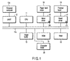
- FIG. 1 shows the system configuration of a thermal printer.
- 11 denotes a CPU (central processing unit) that exercises control over the thermal printer.
- a system bus 11a from the CPU 11 are connected to a UART (asynchronous receiver/transmitter) 12, an image buffer 13 for storing image data to be printed onto one label, a ROM (read only memory) 14 that stores such control programs as shown in FIGS. 2 and 3, a RAM (random access memory) 15 that stores working areas, a motor driver 16 as printing speed control means, and a head driver 17 as thermal head driving means.
- UART asynchronous receiver/transmitter
- ROM read only memory
- RAM random access memory
- the motor driver 16 is equipped with a memory 16t which stores a printing speed V at which a continuous form is carried from when one line is printed until the next line is printed.
- the motor driver 16 controls the driving of a paper feed motor 18 as transport means that transports a continuous form as shown in FIG. 5 on the basis of the printing speed V stored in the memory 16t.
- the paper feed motor 18 comprises a stepping motor and the printing speed V is determined by the rotational speed of the stepping motor.
- a thermal head 19 is connected to the head driver 17, which has a memory 17t that stores an application time T which is an energizing time during which heating elements are energized to print one line.
- the head driver 17 controls the energization of the thermal head 19 on the basis of the application time T stored in the memory 17t.
- the system bus 11a is connected to a character ROM 20, which has bit map data that converts print data sent from an externally connected personal computer 12a into image data.
- the personal computer (PC) 12a is connected to the UART 12.
- the thermal printer is fed with such a continuous form (recording medium) as shown in FIG. 5.
- the continuous form is pasted in succession with delivery slips each comprising an A section and a B section to form one page.
- delivery slips each comprising an A section and a B section to form one page.
- the A section indicates the tag section
- the B section indicates the slip section.
- FIG. 4 shows printed contents of a delivery slip for one page.
- FIG. 6 is a sectional view of the A section and the B section of the delivery slip of FIG. 5.
- the A section is a print area where copying is unnecessary and the B section is a print area where copying is necessary.
- the slip section needs copying because of the necessity of at least an invoice and a business management slip.
- the print area A where copying is unnecessary and the print area B where copying is necessary are set by the personal computer 12a.
- two delivery slips are printed. Namely, two tag sections A are required.
- a commodity is composed of a personal computer body and a keyboard, one tag needs to be attached to each of the personal computer and the keyboard.
- the B section is treated as an area where there is no need of a print copy. This is because, even if goods are divided into two, they are delivered to the same consignee and the slip section B on the second delivery slip does therefore not need copying. Namely, for the slip section, the slip section B on the first delivery slip suffices.
- step S1 Print data for one page, including presence or absence of a copy area and its length (specifically, in millimeters), a lot of parcels or not, and, if lot, how many parcels belong to the lot, are transmitted from the personal computer 12a are received by the label printer and then stored temporarily in the RAM 15 (step S2). The print data temporarily stored in the RAM 15 is subjected to analysis (step S3).
- the received print data is converted by the bit map data stored in the character ROM 20 and stored in the image buffer 13 (step S4).
- Step S5 it is determined whether printing of the rest of the lot must be executed or not.
- the presence of rest parcels means that printing of a plural delivery slip onto a plural sheet of paper must be executed.
- the presence of the rest of the lot means that the article in question consists of a plurality of parcels. Delivery slips must therefore be attached to the respective parcels.
- the printing of the rest of the lot means printing of the second delivery slip and all of the following delivery slips. It is determined based on data of which page of the delivery slips is to be printed whether printing of the second delivery slip and the following delivery slips must be executed.
- step S5 printing is performed (step S6), described in detail later with reference to FIG. 3.
- step S5 the A and B sections are set to non-copy (step S7). After that, printing is carried-out (step S6).
- step S8 If the determination is NO in step S8, then a return is made to step S5.
- step S8 If, on the other hand, the determination is YES in step S8, then a return is made to step S2.
- step S6 the printing process (step S6) in FIG. 2 will be described with reference to the flowchart of FIG. 3.
- step S11 for printing, a determination is made as to whether or not the area is a copy area (step S11).
- step S11 since the A section is an area where copying is unnecessary, in printing onto the A section, the determination in step S11 will be NO.
- an application time adapted for normal heat-sensitive paper is set in the memory 17t (step S12). Further, a printing speed adapted for normal heat-sensitive paper is set in the memory 16t (step S13).
- step S15 a determination is made as to whether or not all the lines have been printed out. If the determination is NO in step S15, then a return is made to step S11.
- step S11 determines whether the application time for copying is YES. If, on the other hand, the determination in step S11 is YES, an application time adapted for copying is set in the memory 17t (step S16).
- the application time for copying is set longer than the application time for normal heat-sensitive paper.
- a printing speed adapted for copying is set in the memory 16t (step S17).
- the printing speed for copying is set lower than the printing speed for normal heat-sensitive paper.
- the applied energy to the print area where copying is unnecessary can be lowered. Therefore, the applied energy can be set most suitably.
- the printing speed can be set most suitably. Namely, high-speed printing is allowed.
- step S11 The determination of whether or not a print area is an area where copying is necessary (step S11) is made on a line-by-line basis as shown in FIG. 3. Therefore, even when one sheet is scattered with areas where copying is necessary and areas where copying is unnecessary, the applied energy can be lowered and the printing speed can be increased for print areas where copying is unnecessary.
- the embodiment is arranged to both lower the applied energy and increase the printing speed for areas where copying is unnecessary, only the applied energy may be lowered or only the printing speed may be increased. Conversely, for areas where copying is necessary, the applied energy may be increased and the printing speed may be decreased.
- the print area A where copying is unnecessary and the print area B where copying is necessary are set by the personal computer 12a; otherwise, they may be stored beforehand in a memory (e.g., the RAM 15) in the thermal printer.
- a memory e.g., the RAM 15
- the applied energy and the printing speed can be set most suitably.
- the present invention is effective in the technical field of thermal printers that print delivery slips in the distribution business of home delivery systems.
Landscapes
- Electronic Switches (AREA)
- Record Information Processing For Printing (AREA)
- Printers Characterized By Their Purpose (AREA)
Abstract
Description
Claims (20)
- A thermal printer that prints onto a recording medium having a print area where copying is unnecessary and a print area where copying is necessary on one page, characterized by comprising:a thermal head; andthermal head driving means for driving the thermal head so as to decrease the energy supplied to the thermal head for the print area where copying is unnecessary below that for the print area where copying is necessary.
- A thermal printer that prints onto a recording medium having a print area where copying is unnecessary and a print area where copying is necessary on one page, characterized by comprising:transport means for transporting the recording medium; andprinting speed control means for controlling the transport means so as to increase the printing speed for the print area where copying is unnecessary above that for the print area where copying is necessary.
- A thermal printer that prints onto a recording medium having a page where copying is unnecessary and a page where copying is necessary, characterized by comprising:transport means for transporting the recording medium; andprinting speed control means for controlling the transport means so as to increase the printing speed for the page where copying is unnecessary above that for the page where copying is necessary.
- The thermal printer according to claim 1, characterized in that the area where copying is unnecessary and the area where copying is necessary are set up from a personal computer.
- The thermal printer according to claim 2, characterized in that the area where copying is unnecessary and the area where copying is necessary are set up from a personal computer.
- A thermal printer that prints onto a recording medium having a print area where copying is unnecessary and a print area where copying is necessary on one page, characterized by comprising:a thermal head; andthermal head driving means for driving the thermal head so as to decrease the applied energy to the thermal head for a section in the direction in which the recording medium is transported in the print area where copying is unnecessary below that for a section in the direction in which the recording medium is transported in the print area where copying is necessary.
- A thermal printer that prints onto a recording medium having a print area where copying is unnecessary and a print area where copying is necessary on one page, characterized by comprising:a thermal head;determination means for making a determination of whether or not a print page is the second page or later;setting means for, when the determination means determines that the print page is the second page or later, setting that page as an area where copying is unnecessary; andthermal head driving means for driving the thermal head so as to decrease the applied energy to the thermal head for the print area where copying is unnecessary below that for the print area where copying is necessary.
- A thermal printer that prints onto a recording medium having a print area where copying is unnecessary and a print area where copying is necessary on one page, characterized by comprising:transport means for transporting the recording medium;determination means for determining whether or not a print page is the second page or later;setting means for, when the determination means determines that the print page is the second page or later, setting that page as an area where copying is unnecessary; andprinting speed control means for controlling the transport means so as to increase the printing speed for the print area where copying is unnecessary above that for the print area where copying is necessary.
- A thermal printer that prints onto a recording medium having a page where copying is unnecessary and a page where copying is necessary, characterized by comprising:transport means for transporting the recording medium;determination means for determining whether or not a page needs copying on the basis of a lot of parcels; andprinting speed control means for controlling the transporting means so as to increase the printing speed for the page for which the determination is that copying is unnecessary above that for the page that needs copying.
- A thermal printer that prints onto a recording medium having a page where copying is unnecessary and a page where copying is necessary, characterized by comprising:a thermal head;transport means for transporting the recording medium;determination means for determining whether or not a page needs copying on the basis of a lot of parcels; andprinting control means for driving the thermal head and controlling the transporting means so that the applied energy and the printing speed for the page for which copying is determined unnecessary are respectively decreased and increased below and above the applied energy and the printing speed for the page that needs copying.
- The thermal printer according to claim 1, characterized in that, when it is determined that printing extends over more than one page, the second page and later are set to an area where copying is unnecessary.
- The thermal printer according to claim 2, characterized in that, when it is determined that printing extends over more than one page, the second pager and later are set to an area where copying is unnecessary.
- A thermal printer that prints onto a recording medium having a print area where copying is unnecessary and a print area where copying is necessary on one page, characterized by comprising:a thermal head;transport means for transporting the recording medium; andprinting control means for driving the thermal head and controlling the transporting means so that the applied energy and the printing speed for the print area where copying is unnecessary are respectively decreased and increased below and above the applied energy and the printing speed for the print area where copying is necessary.
- The thermal printer according to claim 1, characterized in that the recording medium is a delivery slip.
- The thermal printer according to claim 2, characterized in that the recording medium is a delivery slip.
- A thermal printer that prints onto a recording medium having a print area where copying is unnecessary and a print area where copying is necessary on one page, characterized by comprising:a thermal head; andthermal head driving means for driving the thermal head so as to increase the applied energy to the thermal head for the print area where copying is necessary above that for the print area where copying is unnecessary.
- A thermal printer that prints onto a recording medium having a print area where copying is unnecessary and a print area where copying is necessary on one page, characterized by comprising:transport means for transporting the recording medium; andprinting speed control means for controlling the transport means so as to decrease the printing speed for the print area where copying is necessary below that for the print area where copying is unnecessary.
- A method for driving a thermal printer that prints onto a recording medium having a print area where copying is unnecessary and a print area where copying is necessary on one page, characterized by comprising:a thermal head driving step of driving the thermal head so as to decrease the applied energy to the thermal head for the print area where copying is unnecessary below that for the print area where copying is necessary.
- The method according to claim 18, characterized in that the print area where copying is unnecessary is printed prior to the print area where copying is necessary.
- A method for driving a thermal printer that prints onto a recording medium having a print area where copying is unnecessary and a print area where copying is necessary on one page, characterized by comprising:a printing speed control step of controlling transport means for transporting the recording medium so as to increase the printing speed for the print area where copying is unnecessary above that for the print area where copying is necessary.
Applications Claiming Priority (3)
| Application Number | Priority Date | Filing Date | Title |
|---|---|---|---|
| JP2000164820A JP2001341338A (en) | 2000-06-01 | 2000-06-01 | Thermal printer |
| JP2000164820 | 2000-06-01 | ||
| PCT/JP2001/004658 WO2001092018A1 (en) | 2000-06-01 | 2001-06-01 | Thermal printer |
Publications (3)
| Publication Number | Publication Date |
|---|---|
| EP1225051A1 true EP1225051A1 (en) | 2002-07-24 |
| EP1225051A4 EP1225051A4 (en) | 2003-01-29 |
| EP1225051B1 EP1225051B1 (en) | 2008-02-27 |
Family
ID=18668390
Family Applications (1)
| Application Number | Title | Priority Date | Filing Date |
|---|---|---|---|
| EP01934499A Expired - Lifetime EP1225051B1 (en) | 2000-06-01 | 2001-06-01 | Thermal printer |
Country Status (6)
| Country | Link |
|---|---|
| US (1) | US6683635B2 (en) |
| EP (1) | EP1225051B1 (en) |
| JP (1) | JP2001341338A (en) |
| DE (1) | DE60132970T2 (en) |
| ES (1) | ES2301544T3 (en) |
| WO (1) | WO2001092018A1 (en) |
Families Citing this family (2)
| Publication number | Priority date | Publication date | Assignee | Title |
|---|---|---|---|---|
| JP4135020B2 (en) * | 2006-06-06 | 2008-08-20 | ブラザー工業株式会社 | Recording device |
| JP5313471B2 (en) * | 2007-08-30 | 2013-10-09 | キヤノン電子株式会社 | Recording apparatus, portable terminal, and recording method |
Family Cites Families (9)
| Publication number | Priority date | Publication date | Assignee | Title |
|---|---|---|---|---|
| JPH0761716B2 (en) * | 1984-04-27 | 1995-07-05 | 株式会社日立製作所 | Thermal transfer recording device |
| JP2921035B2 (en) * | 1989-10-12 | 1999-07-19 | ソニー株式会社 | Printing method of thermal printer |
| US4990930A (en) * | 1990-06-04 | 1991-02-05 | Eastman Kodak Company | High speed thermal printing apparatus |
| US5355152A (en) * | 1992-09-24 | 1994-10-11 | Pitney Bowes Inc. | Thermal ribbon encoder assembly for a thermal printing postage meter |
| JPH0747724A (en) * | 1993-08-05 | 1995-02-21 | Fuji Xerox Co Ltd | Printer |
| JPH0890833A (en) * | 1994-09-28 | 1996-04-09 | Canon Inc | Recording device |
| JPH08118697A (en) | 1994-10-20 | 1996-05-14 | Alps Electric Co Ltd | Thermal transfer printer |
| JPH08258302A (en) | 1995-03-17 | 1996-10-08 | Alps Electric Co Ltd | Thermal transfer printer and copy printing method thereof |
| JP2000071574A (en) * | 1998-09-03 | 2000-03-07 | Canon Inc | Printer driver, printer, printer system, recording medium |
-
2000
- 2000-06-01 JP JP2000164820A patent/JP2001341338A/en active Pending
-
2001
- 2001-06-01 EP EP01934499A patent/EP1225051B1/en not_active Expired - Lifetime
- 2001-06-01 DE DE60132970T patent/DE60132970T2/en not_active Expired - Fee Related
- 2001-06-01 WO PCT/JP2001/004658 patent/WO2001092018A1/en not_active Ceased
- 2001-06-01 ES ES01934499T patent/ES2301544T3/en not_active Expired - Lifetime
-
2002
- 2002-01-31 US US10/061,853 patent/US6683635B2/en not_active Expired - Lifetime
Also Published As
| Publication number | Publication date |
|---|---|
| WO2001092018A1 (en) | 2001-12-06 |
| US6683635B2 (en) | 2004-01-27 |
| JP2001341338A (en) | 2001-12-11 |
| DE60132970D1 (en) | 2008-04-10 |
| EP1225051B1 (en) | 2008-02-27 |
| EP1225051A4 (en) | 2003-01-29 |
| ES2301544T3 (en) | 2008-07-01 |
| US20020071021A1 (en) | 2002-06-13 |
| DE60132970T2 (en) | 2009-02-26 |
Similar Documents
| Publication | Publication Date | Title |
|---|---|---|
| EP0503398B1 (en) | Text and color image printing system | |
| EP0811501A3 (en) | A print data transfer system for a thermal demand printer | |
| EP0859497A3 (en) | Print interruption method, and information processing apparatus, output control apparatus, print interruption system and print interruption program stored on a storage medium | |
| US6683635B2 (en) | Thermal printer | |
| RU2437772C2 (en) | Duplex thermal printing | |
| JPH1185923A (en) | Bill issuing device | |
| JP2000109037A (en) | Printing device for delivery label with IC | |
| JPH05205084A (en) | Bar code printer | |
| JP2002067411A (en) | Thermal printer | |
| US5420783A (en) | Control logic power down circuit | |
| JP2899456B2 (en) | Label printer | |
| JP2000112354A (en) | Delivery label with IC | |
| JP2002193449A (en) | Receiving inspection system and receiving inspection method | |
| JP2022107433A (en) | Image forming device and control method thereof | |
| JPH0532243A (en) | Label printer | |
| JP2535623Y2 (en) | Ink ribbon end detection device | |
| JP2006035809A (en) | Printer controller | |
| JPH0624054A (en) | Printer | |
| JPH04347670A (en) | Label printer | |
| JPH04229290A (en) | thermal transfer printer | |
| JPH07123766A (en) | Motor control device | |
| JP2635241B2 (en) | Label printer | |
| JP2000218837A (en) | Thermal printer | |
| JP2009154298A (en) | Recording device and control method for recording device | |
| JPH05318836A (en) | Printer |
Legal Events
| Date | Code | Title | Description |
|---|---|---|---|
| PUAI | Public reference made under article 153(3) epc to a published international application that has entered the european phase |
Free format text: ORIGINAL CODE: 0009012 |
|
| 17P | Request for examination filed |
Effective date: 20020202 |
|
| AK | Designated contracting states |
Kind code of ref document: A1 Designated state(s): BE DE ES FR GB |
|
| RIC1 | Information provided on ipc code assigned before grant |
Free format text: 7B 41J 2/35 A, 7B 41J 2/32 B |
|
| A4 | Supplementary search report drawn up and despatched |
Effective date: 20021212 |
|
| 17Q | First examination report despatched |
Effective date: 20041222 |
|
| 17Q | First examination report despatched |
Effective date: 20041222 |
|
| GRAP | Despatch of communication of intention to grant a patent |
Free format text: ORIGINAL CODE: EPIDOSNIGR1 |
|
| GRAS | Grant fee paid |
Free format text: ORIGINAL CODE: EPIDOSNIGR3 |
|
| GRAA | (expected) grant |
Free format text: ORIGINAL CODE: 0009210 |
|
| AK | Designated contracting states |
Kind code of ref document: B1 Designated state(s): BE DE ES FR GB |
|
| REG | Reference to a national code |
Ref country code: GB Ref legal event code: FG4D |
|
| REF | Corresponds to: |
Ref document number: 60132970 Country of ref document: DE Date of ref document: 20080410 Kind code of ref document: P |
|
| REG | Reference to a national code |
Ref country code: ES Ref legal event code: FG2A Ref document number: 2301544 Country of ref document: ES Kind code of ref document: T3 |
|
| ET | Fr: translation filed | ||
| PLBE | No opposition filed within time limit |
Free format text: ORIGINAL CODE: 0009261 |
|
| STAA | Information on the status of an ep patent application or granted ep patent |
Free format text: STATUS: NO OPPOSITION FILED WITHIN TIME LIMIT |
|
| 26N | No opposition filed |
Effective date: 20081128 |
|
| PGFP | Annual fee paid to national office [announced via postgrant information from national office to epo] |
Ref country code: BE Payment date: 20090619 Year of fee payment: 9 |
|
| PGFP | Annual fee paid to national office [announced via postgrant information from national office to epo] |
Ref country code: ES Payment date: 20090709 Year of fee payment: 9 |
|
| PGFP | Annual fee paid to national office [announced via postgrant information from national office to epo] |
Ref country code: DE Payment date: 20090529 Year of fee payment: 9 Ref country code: GB Payment date: 20090527 Year of fee payment: 9 |
|
| BERE | Be: lapsed |
Owner name: TOSHIBA TEC K.K. Effective date: 20100630 |
|
| GBPC | Gb: european patent ceased through non-payment of renewal fee |
Effective date: 20100601 |
|
| REG | Reference to a national code |
Ref country code: FR Ref legal event code: ST Effective date: 20110228 |
|
| PG25 | Lapsed in a contracting state [announced via postgrant information from national office to epo] |
Ref country code: DE Free format text: LAPSE BECAUSE OF NON-PAYMENT OF DUE FEES Effective date: 20110101 |
|
| PG25 | Lapsed in a contracting state [announced via postgrant information from national office to epo] |
Ref country code: FR Free format text: LAPSE BECAUSE OF NON-PAYMENT OF DUE FEES Effective date: 20100630 |
|
| PG25 | Lapsed in a contracting state [announced via postgrant information from national office to epo] |
Ref country code: BE Free format text: LAPSE BECAUSE OF NON-PAYMENT OF DUE FEES Effective date: 20100630 |
|
| REG | Reference to a national code |
Ref country code: ES Ref legal event code: FD2A Effective date: 20110714 |
|
| PG25 | Lapsed in a contracting state [announced via postgrant information from national office to epo] |
Ref country code: ES Free format text: LAPSE BECAUSE OF NON-PAYMENT OF DUE FEES Effective date: 20110704 Ref country code: GB Free format text: LAPSE BECAUSE OF NON-PAYMENT OF DUE FEES Effective date: 20100601 |
|
| PG25 | Lapsed in a contracting state [announced via postgrant information from national office to epo] |
Ref country code: ES Free format text: LAPSE BECAUSE OF NON-PAYMENT OF DUE FEES Effective date: 20100602 |
|
| PGFP | Annual fee paid to national office [announced via postgrant information from national office to epo] |
Ref country code: FR Payment date: 20090611 Year of fee payment: 9 |