EP1224981A2 - Shaping air distribution methods and apparatus - Google Patents
Shaping air distribution methods and apparatus Download PDFInfo
- Publication number
- EP1224981A2 EP1224981A2 EP02001036A EP02001036A EP1224981A2 EP 1224981 A2 EP1224981 A2 EP 1224981A2 EP 02001036 A EP02001036 A EP 02001036A EP 02001036 A EP02001036 A EP 02001036A EP 1224981 A2 EP1224981 A2 EP 1224981A2
- Authority
- EP
- European Patent Office
- Prior art keywords
- opening
- threaded
- grooves
- forward end
- atomizer
- Prior art date
- Legal status (The legal status is an assumption and is not a legal conclusion. Google has not performed a legal analysis and makes no representation as to the accuracy of the status listed.)
- Withdrawn
Links
Images




Classifications
-
- B—PERFORMING OPERATIONS; TRANSPORTING
- B05—SPRAYING OR ATOMISING IN GENERAL; APPLYING FLUENT MATERIALS TO SURFACES, IN GENERAL
- B05B—SPRAYING APPARATUS; ATOMISING APPARATUS; NOZZLES
- B05B5/00—Electrostatic spraying apparatus; Spraying apparatus with means for charging the spray electrically; Apparatus for spraying liquids or other fluent materials by other electric means
- B05B5/025—Discharge apparatus, e.g. electrostatic spray guns
- B05B5/04—Discharge apparatus, e.g. electrostatic spray guns characterised by having rotary outlet or deflecting elements, i.e. spraying being also effected by centrifugal forces
- B05B5/0403—Discharge apparatus, e.g. electrostatic spray guns characterised by having rotary outlet or deflecting elements, i.e. spraying being also effected by centrifugal forces characterised by the rotating member
- B05B5/0407—Discharge apparatus, e.g. electrostatic spray guns characterised by having rotary outlet or deflecting elements, i.e. spraying being also effected by centrifugal forces characterised by the rotating member with a spraying edge, e.g. like a cup or a bell
-
- B—PERFORMING OPERATIONS; TRANSPORTING
- B05—SPRAYING OR ATOMISING IN GENERAL; APPLYING FLUENT MATERIALS TO SURFACES, IN GENERAL
- B05B—SPRAYING APPARATUS; ATOMISING APPARATUS; NOZZLES
- B05B7/00—Spraying apparatus for discharge of liquids or other fluent materials from two or more sources, e.g. of liquid and air, of powder and gas
- B05B7/02—Spray pistols; Apparatus for discharge
- B05B7/08—Spray pistols; Apparatus for discharge with separate outlet orifices, e.g. to form parallel jets, i.e. the axis of the jets being parallel, to form intersecting jets, i.e. the axis of the jets converging but not necessarily intersecting at a point
- B05B7/0807—Spray pistols; Apparatus for discharge with separate outlet orifices, e.g. to form parallel jets, i.e. the axis of the jets being parallel, to form intersecting jets, i.e. the axis of the jets converging but not necessarily intersecting at a point to form intersecting jets
- B05B7/0815—Spray pistols; Apparatus for discharge with separate outlet orifices, e.g. to form parallel jets, i.e. the axis of the jets being parallel, to form intersecting jets, i.e. the axis of the jets converging but not necessarily intersecting at a point to form intersecting jets with at least one gas jet intersecting a jet constituted by a liquid or a mixture containing a liquid for controlling the shape of the latter
-
- B—PERFORMING OPERATIONS; TRANSPORTING
- B05—SPRAYING OR ATOMISING IN GENERAL; APPLYING FLUENT MATERIALS TO SURFACES, IN GENERAL
- B05B—SPRAYING APPARATUS; ATOMISING APPARATUS; NOZZLES
- B05B5/00—Electrostatic spraying apparatus; Spraying apparatus with means for charging the spray electrically; Apparatus for spraying liquids or other fluent materials by other electric means
- B05B5/025—Discharge apparatus, e.g. electrostatic spray guns
- B05B5/053—Arrangements for supplying power, e.g. charging power
- B05B5/0533—Electrodes specially adapted therefor; Arrangements of electrodes
Definitions
- This invention relates to the atomization and dispensing of coating materials. It is disclosed in the context of a dispensing system and method for coating materials, such as electrically conductive liquid coating materials, electrically non-conductive liquid coating materials, and fluent pulverulent coating materials, but has utility in other applications as well.
- Such shaping air is dispensed primarily to shape and provide an envelope for the cloud of atomized coating material that forms in front of the atomizer in the space between the atomizer and the article, or target, to be coated by the atomized coating material dispensed from the atomizer.
- Such shaping air is dispensed primarily to shape and provide an envelope for the cloud of atomized coating material that forms in front of the atomizer in the space between the atomizer and the article, or target, to be coated by the atomized coating material dispensed from the atomizer.
- the housings, or shrouds, which somewhat surround and enclose the atomizers of such systems generally include galleries which extend from points remote from the openings in the shrouds through which atomized coating material is dispensed to the regions of the shrouds around the openings.
- Pressurized gases or mixtures of gases, such as, for example, compressed air are supplied to these galleries, and are exhausted from these galleries in'the regions surrounding such openings to provide a shaping air envelope which to some degree contains and shapes the cloud of atomized coating material which is being dispensed from the atomizer.
- Such shrouds typically are constructed from relatively less rigid filled and unfilled resins.
- the shrouds are removed and replaced from time to time during the course of operation of coating application facilities in which they are utilized for routine maintenance and the like.
- a desirable maintenance cycle might be, for example, four hours of uninterrupted operation, followed by whatever maintenance is required, then another four hours of uninterrupted operation, and so on.
- the handling of such a shroud almost inevitably results in the shroud being subject to some deformation. Additionally, the shrouds and other components of such systems are subject to manufacturing tolerance variations.
- Non-uniformity of the shaping air distribution affects, generally by causing non-uniformity of, the pattern of shaping air itself, and resulting non-uniformity of the pattern of coating material in the coating material cloud dispensed from the atomizer.
- a coating dispensing apparatus includes an atomizer and a housing for the atomizer.
- the housing includes a forward end defining an opening through which coating material dispensed by the atomizer is discharged.
- the forward end includes an inner portion and an outer portion.
- One of the inner portion and the outer portion includes a first surface.
- the other of the inner and outer portions includes a second surface.
- At least one of the first and second surfaces includes grooves which extend to the forward end and terminate around the opening. Compressed gas supplied to the grooves remote from the opening flows toward the forward end and exits from the grooves around the opening.
- the coating dispensing apparatus includes a plenum chamber remote from the opening.
- the grooves intersect the plenum chamber remote from the opening.
- the first and second surfaces are complementarily shaped.
- the complementarily shaped first and second surfaces include complementarily shaped frusta of a solid, for example, a cone.
- the inner and outer portions include complementarily threaded portions.
- the threaded portion of the inner portion is threaded, remotely from the opening, into the threaded portion of the outer portion.
- the threaded portion of the outer portion includes an internally threaded region and the threaded portion of the inner portion includes an externally threaded region.
- the threads of the externally threaded region engage the threads of the internally threaded region to orient the first and second surfaces adjacent one another.
- an atomizer 20 includes a manifold assembly 22 for providing the various services 23, such as high and low pressure compressed air, high and low pressure solvent, coating material, and the like to the atomizer 20.
- the identity of the solvent depends upon the type of coating material being dispensed.
- a typical solvent might be, for example, water or a volatile organic compound.
- the various services 23 are provided to a valve module assembly 24 by which flows of the various services to the atomizer 20 are controlled.
- a module retaining ring 25 retains the module assembly 24 on the manifold assembly 22.
- a typical, although by no means the only, atomizer 20 includes a gas-powered turbine 26 which spins a bell cup 28. Illustratively, turbine 26 is powered by compressed air.
- Bell cup 28 may be of the general type described in, for example, one of the following U. S. Patents, the disclosures of which are hereby incorporated herein by reference: 5,433,387; 5,622,563; 5,633,306; 5,662,278; 5,957,395; 6,042,030; and, 6,076,751. Again, no representation is intended that a complete search of all pertinent art has been conducted or that there is no better art than that listed. Nor should any such representation be inferred.
- the turbine 26 and bell cup 28 are housed within a shroud 30 including an outer portion 32 which is attached, for example, by engagement of threads 34 on the shroud 30 and manifold 22, to form the assembly 20.
- the illustrated assembly 20 dispenses conductive coating material which is then charged by a charging mechanism 36 including a high voltage charging ring 38, electrodes 40 which extend axially forward and radially outward at acute angles to a rotational axis of turbine 26 from the high voltage charging ring 38, a high voltage coupling tube 42 and a high voltage coupling compression nut 44 by which assembly 20 is coupled to a high-magnitude potential supply of the general type disclosed in, for example, one of the following U. S.
- the shroud 30 includes an outer, somewhat projectile shaped portion 46, the forward end 48 of which is open to permit the discharge of atomized coating material from the forward end of bell cup 28 therethrough.
- the shroud 30 is provided with an internally screw-threaded portion 50 into which is threaded an externally screw-threaded portion 54. See Figs. 4-5.
- the two portions 50, 54 are pinned together at a position at which axially extending reliefs 56 in both mate by pressing pins 58 having appropriate cross-sectional configurations into the mating reliefs 56 of the two portions 50, 54. See Figs. 6-7, In another configuration of the shroud 30 illustrated in Figs.
- the outer shroud 30 itself includes a rearward portion 60 and a forward portion, or shaping air cap, 62.
- the rearward portion 60 is provided with an open forward end having internal threads 64.
- the forward portion 62 is provided with an open rearward end having external threads 66.
- the forward portion 62 is threaded into the rearward portion 60.
- the two portions 60, 62 are pinned together at a position at which axially extending reliefs 56 in both mate by pressing pins 58 having appropriate cross-sectional configurations into the mating reliefs 56 of the two portions 60, 62.
- portion 54, 62 itself is internally threaded 72 to engage external threads 74 on a shaping air ring 76. See Figs. 10-14.
- shaping air ring 76 are provided on the outer surface 78 thereof adjacent its rearward end 80. Forwardly from external threads 74, shaping air ring 76 is provided with a somewhat frustoconical outer surface 82 the configuration of which is complementary to the configuration of an inner surface 84 of shroud outer portion 46 or forward portion 62. Surface 82 is provided with a number, illustratively ninety, of axially forwardly and radially inwardly extending, uniformly angularly spaced grooves 88 which extend from a circumferentially extending groove which cooperates with shroud 30 to form an air distribution plenum 90. Air plenum 90 is provided with air in somewhat the same manner as described in, for example, U. S. Patent 5,632,448. The air is distributed uniformly around the front opening 48 in shroud 30 through the grooves 88 which open into an end face 94 of shaping air ring 76.
Landscapes
- Nozzles (AREA)
- Electrostatic Spraying Apparatus (AREA)
Abstract
A coating dispensing apparatus includes an atomizer (20) and a housing (30) for
the atomizer. The housing includes a forward end defining an opening through which
coating material dispensed by the atomizer is discharged. The forward end (48) includes
an inner portion and an outer portion (46). One of the inner portion and the outer portion
includes a first surface. The other of the inner and outer portions includes a second
surface. At least one of the first and second surfaces includes grooves (88) which extend
to the forward end and terminate around the opening. Compressed gas supplied to the
grooves remote from the opening flows toward the forward end and exits from the
grooves around the opening.
Description
This invention relates to the atomization and dispensing of coating
materials. It is disclosed in the context of a dispensing system and method for coating
materials, such as electrically conductive liquid coating materials, electrically non-conductive
liquid coating materials, and fluent pulverulent coating materials, but has
utility in other applications as well.
Various apparatus and methods for distributing so-called shaping air
around an atomizer are known. Such shaping air is dispensed primarily to shape and
provide an envelope for the cloud of atomized coating material that forms in front of
the atomizer in the space between the atomizer and the article, or target, to be coated
by the atomized coating material dispensed from the atomizer. There are, for
example, the systems illustrated and described in U. S. Patents 5,632,448 and
5,853,126, the disclosures of which are hereby incorporated herein by reference. No
representation is intended that a complete search of all pertinent art has been
conducted or that there is no better art than that listed. Nor should any such
representation be inferred.
The housings, or shrouds, which somewhat surround and enclose the
atomizers of such systems generally include galleries which extend from points
remote from the openings in the shrouds through which atomized coating material is
dispensed to the regions of the shrouds around the openings. Pressurized gases or
mixtures of gases, such as, for example, compressed air, are supplied to these
galleries, and are exhausted from these galleries in'the regions surrounding such
openings to provide a shaping air envelope which to some degree contains and shapes
the cloud of atomized coating material which is being dispensed from the atomizer.
Such shrouds typically are constructed from relatively less rigid filled
and unfilled resins. The shrouds are removed and replaced from time to time during
the course of operation of coating application facilities in which they are utilized for
routine maintenance and the like. A desirable maintenance cycle might be, for
example, four hours of uninterrupted operation, followed by whatever maintenance is
required, then another four hours of uninterrupted operation, and so on. The handling
of such a shroud almost inevitably results in the shroud being subject to some
deformation. Additionally, the shrouds and other components of such systems are
subject to manufacturing tolerance variations. All of these factors contribute to non-uniformity
of the pattern such as, for example, by causing asymmetry of the shaping
air envelope around the opening in the remote end of the shroud which surrounds the
nozzle or bell cup from which the coating material is dispensed. Non-uniformity of
the shaping air distribution affects, generally by causing non-uniformity of, the
pattern of shaping air itself, and resulting non-uniformity of the pattern of coating
material in the coating material cloud dispensed from the atomizer.
Additionally, proposals have been advanced to monitor the flow of
shaping air, with the objective of determining when variation in the flow rate of
shaping air varies from some established nominal value by some predetermined
amount. The thought is that if and as such variations occur, they signal less than
optimal performance of the coating material atomizing and dispensing systems, and
indicate the need for curative maintenance. If any of such proposals are ultimately
implemented, there must be some nominal level of performance of a dispensing
system, for example, an agreed-upon uniform shaping air envelope, against which any
monitored flow can be measured.
According to the invention, a coating dispensing apparatus includes an
atomizer and a housing for the atomizer. The housing includes a forward end defining
an opening through which coating material dispensed by the atomizer is discharged.
The forward end includes an inner portion and an outer portion. One of the inner
portion and the outer portion includes a first surface. The other of the inner and outer
portions includes a second surface. At least one of the first and second surfaces
includes grooves which extend to the forward end and terminate around the opening.
Compressed gas supplied to the grooves remote from the opening flows toward the
forward end and exits from the grooves around the opening.
Illustratively according to the invention, the coating dispensing
apparatus includes a plenum chamber remote from the opening. The grooves intersect
the plenum chamber remote from the opening.
Further illustratively according to the invention, except for the grooves
provided in the at least one of the first and second surfaces, the first and second
surfaces are complementarily shaped.
Illustratively according to the invention, the complementarily shaped
first and second surfaces include complementarily shaped frusta of a solid, for
example, a cone.
Additionally illustratively according to the invention, the inner and
outer portions include complementarily threaded portions. The threaded portion of
the inner portion is threaded, remotely from the opening, into the threaded portion of
the outer portion.
Further illustratively according to the invention, the threaded portion of
the outer portion includes an internally threaded region and the threaded portion of the
inner portion includes an externally threaded region. The threads of the externally
threaded region engage the threads of the internally threaded region to orient the first
and second surfaces adjacent one another.
The invention may best be understood by referring to the following
detailed description and accompanying drawings which illustrate the invention. In the
drawings:
Referring now particularly to Fig. 1, an atomizer 20 includes a
manifold assembly 22 for providing the various services 23, such as high and low
pressure compressed air, high and low pressure solvent, coating material, and the like
to the atomizer 20. The identity of the solvent depends upon the type of coating
material being dispensed. A typical solvent might be, for example, water or a volatile
organic compound. The various services 23 are provided to a valve module assembly
24 by which flows of the various services to the atomizer 20 are controlled. A module
retaining ring 25 retains the module assembly 24 on the manifold assembly 22. A
typical, although by no means the only, atomizer 20 includes a gas-powered turbine
26 which spins a bell cup 28. Illustratively, turbine 26 is powered by compressed air.
Bell cup 28 may be of the general type described in, for example, one of the following
U. S. Patents, the disclosures of which are hereby incorporated herein by reference:
5,433,387; 5,622,563; 5,633,306; 5,662,278; 5,957,395; 6,042,030; and, 6,076,751.
Again, no representation is intended that a complete search of all pertinent art has
been conducted or that there is no better art than that listed. Nor should any such
representation be inferred.
The turbine 26 and bell cup 28 are housed within a shroud 30 including
an outer portion 32 which is attached, for example, by engagement of threads 34 on
the shroud 30 and manifold 22, to form the assembly 20. The illustrated assembly 20
dispenses conductive coating material which is then charged by a charging
mechanism 36 including a high voltage charging ring 38, electrodes 40 which extend
axially forward and radially outward at acute angles to a rotational axis of turbine 26
from the high voltage charging ring 38, a high voltage coupling tube 42 and a high
voltage coupling compression nut 44 by which assembly 20 is coupled to a high-magnitude
potential supply of the general type disclosed in, for example, one of the
following U. S. Patents, the disclosures of which are hereby incorporated herein by
reference: 5,632,816; 5,978,244; 6,144,570; and the references cited in all of these.
Again, no representation is intended that a complete search of all pertinent art has
been conducted or that there is no better art than that listed. Nor should any such
representation be inferred. It should be understood that the invention may also be
used with a system in which the coating material is directly charged, for example, by
contact with (an) electrically charged surface(s), for example, on the bell cup 28
which is (are) maintained at high-magnitude electrostatic potential.
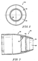
Referring now particularly to Figs. 2-3, the shroud 30 includes an
outer, somewhat projectile shaped portion 46, the forward end 48 of which is open to
permit the discharge of atomized coating material from the forward end of bell cup 28
therethrough. Illustratively, the shroud 30 is provided with an internally screw-threaded
portion 50 into which is threaded an externally screw-threaded portion 54.
See Figs. 4-5. The two portions 50, 54 are pinned together at a position at which
axially extending reliefs 56 in both mate by pressing pins 58 having appropriate cross-sectional
configurations into the mating reliefs 56 of the two portions 50, 54. See
Figs. 6-7, In another configuration of the shroud 30 illustrated in Figs. 8-9, the outer
shroud 30 itself includes a rearward portion 60 and a forward portion, or shaping air
cap, 62. The rearward portion 60 is provided with an open forward end having
internal threads 64. The forward portion 62 is provided with an open rearward end
having external threads 66. The forward portion 62 is threaded into the rearward
portion 60. The two portions 60, 62 are pinned together at a position at which axially
extending reliefs 56 in both mate by pressing pins 58 having appropriate cross-sectional
configurations into the mating reliefs 56 of the two portions 60, 62. In either
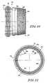
event, portion 54, 62 itself is internally threaded 72 to engage external threads 74 on a
shaping air ring 76. See Figs. 10-14.
The external threads 74 on shaping air ring 76 are provided on the
outer surface 78 thereof adjacent its rearward end 80. Forwardly from external
threads 74, shaping air ring 76 is provided with a somewhat frustoconical outer
surface 82 the configuration of which is complementary to the configuration of an
inner surface 84 of shroud outer portion 46 or forward portion 62. Surface 82 is
provided with a number, illustratively ninety, of axially forwardly and radially
inwardly extending, uniformly angularly spaced grooves 88 which extend from a
circumferentially extending groove which cooperates with shroud 30 to form an air
distribution plenum 90. Air plenum 90 is provided with air in somewhat the same
manner as described in, for example, U. S. Patent 5,632,448. The air is distributed
uniformly around the front opening 48 in shroud 30 through the grooves 88 which
open into an end face 94 of shaping air ring 76.
Claims (6)
- A coating dispensing apparatus including an atomizer, a housing for the atomizer, the housing including a forward end defining an opening through which coating material dispensed by the atomizer is discharged, the forward end including an inner portion and an outer portion, one of the inner portion and the outer portion including a first surface, the other of the inner and outer portions including a second surface, at least one of the first and second surfaces including grooves which extend to the forward end and terminate around the opening, compressed gas supplied to the grooves remote from the opening flowing toward the forward end and exiting from the grooves around the opening.
- The coating dispensing apparatus of claim 1 further including a plenum chamber remote from the opening, the grooves intersecting the plenum chamber remote from the opening.
- The coating dispensing apparatus of claim 1 or 2 wherein except for the grooves provided in the at least one of the first and second surfaces, the first and second surfaces are complementarily shaped.
- The coating dispensing apparatus of claim 3 wherein the complementarily shaped first and second surfaces include complementarily shaped frusta of a solid.
- The coating dispensing apparatus of at least one of the preceding claims wherein the inner and outer portions include complementary threaded portions, the threaded portion of the inner portion being threaded, remotely from the opening, into the threaded portion of the outer portion.
- The coating dispensing apparatus of claim 5 wherein the threaded portion of the outer portion includes an internally threaded region and the threaded portion of the inner portion includes an externally threaded region, the threads of the externally threaded region engaging the threads of the internally threaded region to orient the first and second surfaces adjacent one another.
Applications Claiming Priority (2)
| Application Number | Priority Date | Filing Date | Title |
|---|---|---|---|
| US766106 | 1985-08-15 | ||
| US09/766,106 US20020096582A1 (en) | 2001-01-19 | 2001-01-19 | Shaping air distribution methods and apparatus |
Publications (1)
| Publication Number | Publication Date |
|---|---|
| EP1224981A2 true EP1224981A2 (en) | 2002-07-24 |
Family
ID=25075423
Family Applications (1)
| Application Number | Title | Priority Date | Filing Date |
|---|---|---|---|
| EP02001036A Withdrawn EP1224981A2 (en) | 2001-01-19 | 2002-01-18 | Shaping air distribution methods and apparatus |
Country Status (4)
| Country | Link |
|---|---|
| US (1) | US20020096582A1 (en) |
| EP (1) | EP1224981A2 (en) |
| CA (1) | CA2367886A1 (en) |
| MX (1) | MXPA02000703A (en) |
Cited By (1)
| Publication number | Priority date | Publication date | Assignee | Title |
|---|---|---|---|---|
| EP2408568B1 (en) | 2009-03-19 | 2016-12-21 | Dürr Systems AG | Electrode assembly for an electrostatic atomizer |
Families Citing this family (4)
| Publication number | Priority date | Publication date | Assignee | Title |
|---|---|---|---|---|
| US7070130B1 (en) * | 2002-11-06 | 2006-07-04 | E. I. Dupont De Nemours And Company | Rotatable electrode ring and use thereof in electrostatically assisted high-speed rotary application of spray coating agents |
| USD688743S1 (en) * | 2009-03-13 | 2013-08-27 | Dürr Systems GmbH | Linear color changer |
| USD659753S1 (en) * | 2009-04-20 | 2012-05-15 | Panasonic Electric Works Sunx, Co., Ltd. | Light irradiation device for print machine |
| JP2014205093A (en) * | 2013-04-11 | 2014-10-30 | ランズバーグ・インダストリー株式会社 | Rotary atomization type electrostatic coater |
Citations (8)
| Publication number | Priority date | Publication date | Assignee | Title |
|---|---|---|---|---|
| US5433387A (en) | 1992-12-03 | 1995-07-18 | Ransburg Corporation | Nonincendive rotary atomizer |
| US5622563A (en) | 1992-12-03 | 1997-04-22 | Ransburg Corporation | Nonincedive rotary atomizer |
| US5632448A (en) | 1995-01-25 | 1997-05-27 | Ransburg Corporation | Rotary powder applicator |
| US5632816A (en) | 1994-07-12 | 1997-05-27 | Ransburg Corporation | Voltage block |
| US5853126A (en) | 1997-02-05 | 1998-12-29 | Illinois Tool Works, Inc. | Quick disconnect for powder coating apparatus |
| US5957395A (en) | 1997-10-21 | 1999-09-28 | Illinois Tool Works Inc. | Safe charging |
| US6042030A (en) | 1998-03-23 | 2000-03-28 | Howe; Varce E. | Safe charging with non-insulative atomizer |
| US6076751A (en) | 1998-12-15 | 2000-06-20 | Illinois Tool Works Inc. | Method of charging using nonincendive rotary atomizer |
-
2001
- 2001-01-19 US US09/766,106 patent/US20020096582A1/en not_active Abandoned
-
2002
- 2002-01-15 CA CA002367886A patent/CA2367886A1/en not_active Abandoned
- 2002-01-18 EP EP02001036A patent/EP1224981A2/en not_active Withdrawn
- 2002-01-18 MX MXPA02000703A patent/MXPA02000703A/en unknown
Patent Citations (10)
| Publication number | Priority date | Publication date | Assignee | Title |
|---|---|---|---|---|
| US5433387A (en) | 1992-12-03 | 1995-07-18 | Ransburg Corporation | Nonincendive rotary atomizer |
| US5622563A (en) | 1992-12-03 | 1997-04-22 | Ransburg Corporation | Nonincedive rotary atomizer |
| US5633306A (en) | 1992-12-03 | 1997-05-27 | Ransburg Corporation | Nonincendive rotary atomizer |
| US5662278A (en) | 1992-12-03 | 1997-09-02 | Ransburg Corporation | Method for treating non-conductive rotary atomizer |
| US5632816A (en) | 1994-07-12 | 1997-05-27 | Ransburg Corporation | Voltage block |
| US5632448A (en) | 1995-01-25 | 1997-05-27 | Ransburg Corporation | Rotary powder applicator |
| US5853126A (en) | 1997-02-05 | 1998-12-29 | Illinois Tool Works, Inc. | Quick disconnect for powder coating apparatus |
| US5957395A (en) | 1997-10-21 | 1999-09-28 | Illinois Tool Works Inc. | Safe charging |
| US6042030A (en) | 1998-03-23 | 2000-03-28 | Howe; Varce E. | Safe charging with non-insulative atomizer |
| US6076751A (en) | 1998-12-15 | 2000-06-20 | Illinois Tool Works Inc. | Method of charging using nonincendive rotary atomizer |
Cited By (4)
| Publication number | Priority date | Publication date | Assignee | Title |
|---|---|---|---|---|
| EP2408568B1 (en) | 2009-03-19 | 2016-12-21 | Dürr Systems AG | Electrode assembly for an electrostatic atomizer |
| US9901942B2 (en) | 2009-03-19 | 2018-02-27 | Duerr Systems Gmbh | Electrode assembly for an electrostatic atomizer |
| US10464084B2 (en) | 2009-03-19 | 2019-11-05 | Dürr Systems GmbH | Electrode assembly for an electrostatic atomizer |
| EP2408568B2 (en) † | 2009-03-19 | 2019-12-25 | Dürr Systems AG | Electrode assembly for an electrostatic atomizer |
Also Published As
| Publication number | Publication date |
|---|---|
| US20020096582A1 (en) | 2002-07-25 |
| MXPA02000703A (en) | 2004-11-01 |
| CA2367886A1 (en) | 2002-07-19 |
Similar Documents
| Publication | Publication Date | Title |
|---|---|---|
| EP0379373A1 (en) | Electrostatic rotary atomizing liquid spray coating apparatus | |
| US4273293A (en) | Nozzle assembly for electrostatic spray guns | |
| JP3494680B2 (en) | Triboelectric powder spray gun | |
| CA1164646A (en) | Nozzle assembly for spray coating systems | |
| EP0114064A2 (en) | Nozzle assembly for electrostatic spray guns | |
| CN1057410A (en) | The atomizing cup of rotary sprayer | |
| EP4265992B1 (en) | Electrostatic spray drying nozzle assembly | |
| US6659367B2 (en) | Sprayer device for spraying a liquid coating product | |
| JPH11505173A (en) | Powder spray gun with rotary distributor | |
| US5632448A (en) | Rotary powder applicator | |
| US20020096582A1 (en) | Shaping air distribution methods and apparatus | |
| CN101087661A (en) | Electrostatic coater | |
| CA2466245C (en) | A spray apparatus for coating materials, in particular coating powders | |
| EP0243043B1 (en) | Electrostatic rotary atomizing liquid spray coating apparatus | |
| US6003785A (en) | Composite material bell cup | |
| JPH0724366A (en) | Spray gun for static powder coating application | |
| US3672569A (en) | Electrostatic spray gun nozzle and air cap | |
| US8888018B2 (en) | Powder gun deflector | |
| CN220386858U (en) | Electrostatic atomizing spray head | |
| US20230302470A1 (en) | Electrostatic spray drying nozzle assembly | |
| JPH10235231A (en) | Electrostatic spray gun | |
| RU1796266C (en) | Powder material sprayer | |
| CN121152686A (en) | An air separation ring used to deliver atomizing air and shaping air within a paint spray gun. | |
| JPH08126856A (en) | Triboelectrified gun for electrostatic powder coating | |
| JPH02184361A (en) | Spray gun for electrostatic coating |
Legal Events
| Date | Code | Title | Description |
|---|---|---|---|
| PUAI | Public reference made under article 153(3) epc to a published international application that has entered the european phase |
Free format text: ORIGINAL CODE: 0009012 |
|
| AK | Designated contracting states |
Kind code of ref document: A2 Designated state(s): AT BE CH CY DE DK ES FI FR GB GR IE IT LI LU MC NL PT SE TR |
|
| AX | Request for extension of the european patent |
Free format text: AL;LT;LV;MK;RO;SI |
|
| STAA | Information on the status of an ep patent application or granted ep patent |
Free format text: STATUS: THE APPLICATION IS DEEMED TO BE WITHDRAWN |
|
| 18D | Application deemed to be withdrawn |
Effective date: 20040803 |