EP1224974A1 - Automobile exhaust gas cleaning catalyst metal carrier and production method therefor - Google Patents
Automobile exhaust gas cleaning catalyst metal carrier and production method therefor Download PDFInfo
- Publication number
- EP1224974A1 EP1224974A1 EP00966451A EP00966451A EP1224974A1 EP 1224974 A1 EP1224974 A1 EP 1224974A1 EP 00966451 A EP00966451 A EP 00966451A EP 00966451 A EP00966451 A EP 00966451A EP 1224974 A1 EP1224974 A1 EP 1224974A1
- Authority
- EP
- European Patent Office
- Prior art keywords
- metal
- honeycomb member
- foil
- flat
- exhaust gas
- Prior art date
- Legal status (The legal status is an assumption and is not a legal conclusion. Google has not performed a legal analysis and makes no representation as to the accuracy of the status listed.)
- Withdrawn
Links
Images

Classifications
-
- F—MECHANICAL ENGINEERING; LIGHTING; HEATING; WEAPONS; BLASTING
- F01—MACHINES OR ENGINES IN GENERAL; ENGINE PLANTS IN GENERAL; STEAM ENGINES
- F01N—GAS-FLOW SILENCERS OR EXHAUST APPARATUS FOR MACHINES OR ENGINES IN GENERAL; GAS-FLOW SILENCERS OR EXHAUST APPARATUS FOR INTERNAL-COMBUSTION ENGINES
- F01N13/00—Exhaust or silencing apparatus characterised by constructional features
- F01N13/18—Construction facilitating manufacture, assembly, or disassembly
-
- B—PERFORMING OPERATIONS; TRANSPORTING
- B01—PHYSICAL OR CHEMICAL PROCESSES OR APPARATUS IN GENERAL
- B01J—CHEMICAL OR PHYSICAL PROCESSES, e.g. CATALYSIS OR COLLOID CHEMISTRY; THEIR RELEVANT APPARATUS
- B01J35/00—Catalysts, in general, characterised by their form or physical properties
- B01J35/50—Catalysts, in general, characterised by their form or physical properties characterised by their shape or configuration
- B01J35/56—Foraminous structures having flow-through passages or channels, e.g. grids or three-dimensional [3D] monoliths
- B01J35/57—Honeycombs
-
- F—MECHANICAL ENGINEERING; LIGHTING; HEATING; WEAPONS; BLASTING
- F01—MACHINES OR ENGINES IN GENERAL; ENGINE PLANTS IN GENERAL; STEAM ENGINES
- F01N—GAS-FLOW SILENCERS OR EXHAUST APPARATUS FOR MACHINES OR ENGINES IN GENERAL; GAS-FLOW SILENCERS OR EXHAUST APPARATUS FOR INTERNAL-COMBUSTION ENGINES
- F01N3/00—Exhaust or silencing apparatus having means for purifying, rendering innocuous, or otherwise treating exhaust
- F01N3/08—Exhaust or silencing apparatus having means for purifying, rendering innocuous, or otherwise treating exhaust for rendering innocuous
- F01N3/10—Exhaust or silencing apparatus having means for purifying, rendering innocuous, or otherwise treating exhaust for rendering innocuous by thermal or catalytic conversion of noxious components of exhaust
- F01N3/24—Exhaust or silencing apparatus having means for purifying, rendering innocuous, or otherwise treating exhaust for rendering innocuous by thermal or catalytic conversion of noxious components of exhaust characterised by constructional aspects of converting apparatus
- F01N3/28—Construction of catalytic reactors
- F01N3/2803—Construction of catalytic reactors characterised by structure, by material or by manufacturing of catalyst support
- F01N3/2807—Metal other than sintered metal
- F01N3/281—Metallic honeycomb monoliths made of stacked or rolled sheets, foils or plates
-
- F—MECHANICAL ENGINEERING; LIGHTING; HEATING; WEAPONS; BLASTING
- F01—MACHINES OR ENGINES IN GENERAL; ENGINE PLANTS IN GENERAL; STEAM ENGINES
- F01N—GAS-FLOW SILENCERS OR EXHAUST APPARATUS FOR MACHINES OR ENGINES IN GENERAL; GAS-FLOW SILENCERS OR EXHAUST APPARATUS FOR INTERNAL-COMBUSTION ENGINES
- F01N3/00—Exhaust or silencing apparatus having means for purifying, rendering innocuous, or otherwise treating exhaust
- F01N3/08—Exhaust or silencing apparatus having means for purifying, rendering innocuous, or otherwise treating exhaust for rendering innocuous
- F01N3/10—Exhaust or silencing apparatus having means for purifying, rendering innocuous, or otherwise treating exhaust for rendering innocuous by thermal or catalytic conversion of noxious components of exhaust
- F01N3/24—Exhaust or silencing apparatus having means for purifying, rendering innocuous, or otherwise treating exhaust for rendering innocuous by thermal or catalytic conversion of noxious components of exhaust characterised by constructional aspects of converting apparatus
- F01N3/28—Construction of catalytic reactors
- F01N3/2839—Arrangements for mounting catalyst support in housing, e.g. with means for compensating thermal expansion or vibration
- F01N3/2842—Arrangements for mounting catalyst support in housing, e.g. with means for compensating thermal expansion or vibration specially adapted for monolithic supports, e.g. of honeycomb type
-
- F—MECHANICAL ENGINEERING; LIGHTING; HEATING; WEAPONS; BLASTING
- F01—MACHINES OR ENGINES IN GENERAL; ENGINE PLANTS IN GENERAL; STEAM ENGINES
- F01N—GAS-FLOW SILENCERS OR EXHAUST APPARATUS FOR MACHINES OR ENGINES IN GENERAL; GAS-FLOW SILENCERS OR EXHAUST APPARATUS FOR INTERNAL-COMBUSTION ENGINES
- F01N2450/00—Methods or apparatus for fitting, inserting or repairing different elements
- F01N2450/22—Methods or apparatus for fitting, inserting or repairing different elements by welding or brazing
-
- Y—GENERAL TAGGING OF NEW TECHNOLOGICAL DEVELOPMENTS; GENERAL TAGGING OF CROSS-SECTIONAL TECHNOLOGIES SPANNING OVER SEVERAL SECTIONS OF THE IPC; TECHNICAL SUBJECTS COVERED BY FORMER USPC CROSS-REFERENCE ART COLLECTIONS [XRACs] AND DIGESTS
- Y02—TECHNOLOGIES OR APPLICATIONS FOR MITIGATION OR ADAPTATION AGAINST CLIMATE CHANGE
- Y02A—TECHNOLOGIES FOR ADAPTATION TO CLIMATE CHANGE
- Y02A50/00—TECHNOLOGIES FOR ADAPTATION TO CLIMATE CHANGE in human health protection, e.g. against extreme weather
- Y02A50/20—Air quality improvement or preservation, e.g. vehicle emission control or emission reduction by using catalytic converters
Definitions
- the mainstream of catalyst development for purifying the exhaust gases is the structure made from precious metal catalysts like platinum(Pt) carried on top of such a ceramic honeycomb as cordierite wash-coated by ⁇ -alumina powder.
- the ceramic honeycomb had such drawbacks as having a rather high exhaust resistance, or having a low operating temperature because of a limitation of a heat resistant characteristics of a shock absorbing stainless steel mesh inserted between the honeycomb and an outer tube to prevent a destruction of the honeycomb.
- the metal carriers composed of stainless steel foil have become the mainstream in improving thereof in recent times.
- the metal carriers are generally constituted by the honeycomb formed by laminating or winding a flat metal foil (flat foil) and a corrugate-processed metal foil (corrugated foil), and a metal tube that accommodates the honeycomb.
- the foils are required to have not only high-temperature-strength and oxidation-resistant characteristics to withstand the high-temperature and high-speed exhaust gas in reaction but also anti-thermal-fatigue characteristics to withstand the heating and cooling.
- the connecting method of the honeycomb, the metal tube and the honeycomb needs to be improved in order to have the metal carrier to withstand a higher temperature and higher speed of the exhaust gas.
- Prior arts for those objectives are Japanese Patent Laid-open Publications No. Sho. 61-199574, No. Sho. 62-160728, Japanese Utility model Laid- open Publication No. Sho. 62-194436, Japanese Patent Laid-open Publications No. Sho. 62-273050, No. Hei. 2-102744, No. Hei. 4-71648, and No. Hei. 5-93545.
- a junction structure by a metal carrier is the most preferred structure for an automotive exhaust gas purification, from viewpoints of a thermal stress diffusion, and prevention of a fall-off of the honeycomb due to an erosion of the honeycomb caused by an accidental fire of an engine.
- a metal carrier was proposed, in which the outermost peripheral surface of the metal carrier was connected to the inner peripheral surface of the tubular metal case, and in which the diameter ⁇ B of the tubular hollow portion at the center of this metal carrier was made to be a prescribed value (20/100) ⁇ A ⁇ ⁇ B ⁇ (95/100) ⁇ A, in relation to the outer diameter ⁇ A, and which had a structure with the inner wall of the aforementioned tubular hollow portion supported by a tube made of metal.
- the outermost peripheral surface of the metal carrier was connected to the inner peripheral surface of the tubular metal case, and in which the diameter ⁇ B of the tubular hollow portion at the center of this metal carrier was made to be a prescribed value (20/100) ⁇ A ⁇ ⁇ B ⁇ (95/100) ⁇ A, in relation to the outer diameter ⁇ A, and which had a structure with the inner wall of the aforementioned tubular hollow portion supported by a tube made of metal.
- the present invention was made to solve the above-mentioned conventional problems, and provides a metal carrier for automotive exhaust gas purifying catalysts with durability that can endure the high-temperature and high-speed exhaust gas flow, and durability from having anti-thermal-fatigue characteristics that can endure rapid heating and cooling, and which excels in purifying performances.
- the object of this invention is to improve the durability of the honeycomb member itself, and protect automotive parts in the downstream side, by appropriately processing the free-flat-foil, which is the winding-start portion existing in the tubular hollow portion of the honeycomb member, and existing mainly for the convenience of the manufacturing process, and also by preventing a generation of cracks, and chipping-and-loss.
- the outline of the present invention is as follows:
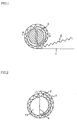
- FIG. 1 is a drawing showing the manufacturing process of a metal carrier and an axis core 3 with a half-dividing partitioning slit of approximately 5mm in diameter, when winding a corrugated foil 2 around a flat foil 1 in spiral form.
- the winding is started with an end portion of the flat foil 1 being inserted into the partitioning slit of the axis core 3, and the corrugated foil 2 is also wound up, and a honeycomb member H is completed by repeating these windings.
- the metal honeycomb member H In manufacturing the honeycomb member H, it is necessary to make the metal honeycomb member so that the member H is decided as ⁇ B ⁇ 10/100 ⁇ ⁇ A, i.e., the outer diameter of the metal carrier is ⁇ A, and the inner diameter of the same is ⁇ B, and also it is necessary to make the member H a hollow metal honeycomb member provided with a tubular flat foil of ⁇ B in diameter at the innermost circumference thereof. This is because, when ⁇ B is bigger than 10/100 ⁇ ⁇ A, the purifying surface area will be too small due to the diameter of the tubular hollow portion being too big, and the purifying performance will be low for a catalyst carrier, and will not be appropriate as a metal carrier for exhaust gas purifying catalysts of vehicles.
- the aforementioned half-divided axis core 3 is extracted, when the aforementioned winding process has been completed.
- a tubular hollow portion 11 is formed at the central portion of the honeycomb construction, as shown in FIG. 2, and a free-flat-foil 4 will remain in the tubular hollow portion 11, traversing the hollow portion in the radial direction.
- the free-flat-foil 4 is the front-end portion of the flat foil 1 used at the start of the winding, and is the portion that has been inserted into the partitioning slit of the axis core, when the winding around of the metal foil was started.
- the metal carrier was fixed to the central portion in this state, by soldering or diffusion connection. But the free-flat-foil 4 is prone to chipping and loss due to fluttering caused by high-speed exhaust gas flow, in this state.
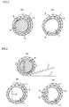
- the free-flat-foil 4 exposed in the tubular hollow portion can be minimized, by cutting and removing the aforementioned free-flat-foil 4 with mechanical means that uses cutting tools 14 such as drills with approximately the same diameter as the outer diameter of the aforementioned axis core 3, as shown in FIG. 3(a), after extracting the half-divided axis core 3.
- cutting tools 14 such as drills with approximately the same diameter as the outer diameter of the aforementioned axis core 3, as shown in FIG. 3(a)
- the free-flat-foil burr is soldered and united to the innermost layer of the hollow tubular portion 11, by soldering and uniting at least one innermost layer (the innermost layer) of the aforementioned hollow metal honeycomb member, along one portion or the whole portion of the contacting surface in the axial direction of the aforementioned hollow metal honeycomb member, after the free-flat-foil 4 is mechanically processed in the axial direction, and hollowed out and removed. Thereby, the durability of the honeycomb member is improved. It should be noted that, general methods could be adopted for soldering methods as publicly known.
- a honeycomb member H is composed by soldering and unifying at least one layer, and preferably pluralities of layers, of one portion or the whole portion of the contacting surface of the flat foil and the corrugated foil, in the inner-circumference axis direction of the honeycomb member H, which includes the portion of the innermost circumference of the honeycomb member having aforementioned free-flat-foil 4 pressed on, as shown in FIG. 5(b).
- the aforementioned free-flat-foil 4 is united with the tubular flat foil in the inner circumference by being provided with the soldered portion 13a.
- the soldering of the innermost layer of the honeycomb member is done across the whole portion of the contacting surface of the flat foil and the corrugated foil in the axial direction of the honeycomb body.
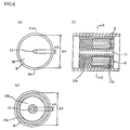
- FIG. 6(a) is a drawing of a metal carrier provided with a honeycomb member H with the free-flat-foil processed as in FIG. 5(a), and FIG. 6(b) shows a sectional view of the state seen from the A-A line in the axial direction in FIG. 6(a).
- FIG. 6(c) is a longitudinal sectional view of the tubular metal carrier, in the direction orthogonal to the axial direction seen at the B-B position. In FIG. 6(c), the soldered and not-soldered areas are shown, but the drawing of the honeycomb structure has been omitted because the drawing will become complicated.
- a disposal of the aforementioned free-flat-foil can be done almost in perfection, by having at least one layer, and preferably pluralities of layers of the inner circumference portion of the honeycomb member H including the free-flat-foil, soldered and united along the whole portion of the contacting surface in the axial direction of the honeycomb member.
- the honeycomb member H has a soldered portion 13a and a non-soldered portion 13b (the portion not soldered).
- the innermost layer of the honeycomb member and the vicinity are soldered on the whole portion in the axial direction, and a part of the layer is also soldered on the whole portion in the radial direction.
- the outermost layer of the honeycomb member and the vicinity are also soldered on the whole portion in the axial direction.
- the non-soldered portion 13b in FIG. 6, and the non-soldered portion 13b in FIG. 7, which is described in the following, can be provided by known methods that mask the portions 13b to prevent adhesives or soldering powders from sticking onto them, for example.
- an eccentric axis core 6 of approximately 5mm in diameter can be used as an axis core for holding the end portion of the flat foil 1, as another embodiment of this invention.
- the eccentric axis core 6 has a structure with a partitioning slit formed by being partially-divided at a portion where it is 1/3 to 1/5 of the diameter away from the outer circumference, as seen in the cross section, and at a portion one to two mm in width.
- the front end portion of the flat foil 1 traversing in the chord direction of the hollow portion of the honeycomb member H remains as a free-flat-foil 4, as shown in FIG. 4(b).
- the free-flat-foil 4 is located in a diameter portion of the tubular hollow portion, and the length of the free-flat-foil 4 is the same as the diameter of the tubular hollow portion.
- the length of the free-flat-foil portion can be made minimum, because an eccentric axis core 6 is used.
- Drawback caused by the aforementioned free-flat-foil can be kept to a minimum, by pressing the aforementioned free-flat-foil 4 along the innermost circumference portion of the metal carrier. Since the free-flat-foil 4 is eccentric inside the tubular hollow portion at a starting portion, it is easy to press the foil 4 onto the innermost circumference portion, as shown in FIG. 4(c). This means is aimed at minimizing the free-flat-foil formed in the manufacturing process, and is very effective means for disposing the free-flat-foil portion.
- the free-flat-foil 4 is less prone to being fluttered or vibrated even in the gas flow, by soldering and uniting at least one of the innermost layers of the hollow metal honeycomb member, along one portion or the whole portion of the contacting surface in the axial direction of the aforementioned hollow metal honeycomb member, even in a condition with the free-flat-foil 4 still remaining inside the tubular hollow portion 11.
- the fluttering and vibration of the free-flat-foil 4 are caused not only by the fact that the free-flat-foil 4 itself exists inside the tubular hollow portion 11 in a traversing state in the radial direction or the chord direction, in other words, is exposed in a hollow portion, but by the fact that the tubular flat foil, which is continuous with the free-flat-foil 4 in the innermost circumference of the tubular hollow portion 11, is not fixed to the surroundings, also promotes the fluttering and vibration of the free-flat-foil.
- the tubular flat foil which is continuous with the free-flat-foil 4 in the innermost circumference of the tubular hollow portion 11
- the free-flat-foil 4 is less prone to being fluttered or vibrated even in the gas flow.
- the following embodiment is proposed in the present invention in addition to the above-mentioned embodiments.
- high-temperature gas flows into the metal carrier, and the honeycomb member H is further heated to a high temperature because the catalyst reaction is a heat generating reaction, and as a result, thermal expansion occurs.
- an outer tube 8 that supports the honeycomb member H from the outside is in contact with outside air, and maintained at a lower temperature than the honeycomb member H. Therefore, the high-temperature honeycomb member H is constrained by the low-temperature outer tube 8, and a thermal stress is generated within the honeycomb member H.
- the metal carrier is required to have anti-thermal-fatigue characteristics.
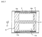
- an intermediate tube 9 is arranged on the outer side of the honeycomb member H, and the outer tube 8 is arranged on the outer side of them.
- the honeycomb member H and the intermediate tube 9 are soldered at a soldered portion 16b on one end in the axial direction of the metal carrier, and a space is given between the honeycomb member H and the intermediate tube 9 at places other than the soldered portion 16b.
- the intermediate tube 9 and the outer tube 8 are also soldered at a soldering-portion 16a on the other end in the axial direction, and a space is given between the intermediate tube 9 and the outer tube 8 at places other than the soldered portion 16a.
- the soldered portion 16b of the intermediate tube 9 expands corresponding to the thermal expansion of the honeycomb member H, but the soldered portion 16a of the intermediate tube 9 does not expand because the portion 16a is not in contact with the honeycomb member H.
- the thermal expansion of the honeycomb member H is not transmitted to the outer tube 8, and the honeycomb member H can expand without being constrained by the outer tube 8.
- the invention shown in FIG. 7 restrains a generation of thermal stress, and can improve the anti-thermal-fatigue characteristics of the metal carrier, and extend the service life durability of the metal carrier, due to the above-mentioned effects. Furthermore, insulation characteristics of the metal carrier can be improved, because two kinds of tubes, the intermediate tube 9 and the outer tube 8, are provided on the outer side of the honeycomb member H, as the tubes to support the honeycomb member H. Furthermore, noises radiated to the exterior thereby generated in the metal carrier can also be reduced.
- the thickness of the intermediate tube 9 should be thin in order to reduce the thermal stress generated when the honeycomb member H thermally expands. It is preferred that the thickness of the intermediate tube 9 must be at least thinner than the thickness of the outer tube 8.
- a metal carrier was manufactured, by preparing a stainless steel flat foil and corrugated foil, with a thickness of 30 ⁇ m, made of Fe-20Cr-5Al (YUS205M1), wound around a stainless steel outer tube, with a thickness of 1.5mm and made of Fe-19Cr-2Mo(YUS190), and making it into a honeycomb structure with a diameter of 66mm and a length of 87mm, and the junction of the aforementioned flat foil and corrugated foil, which constitute the aforementioned honeycomb structure member, was done at the end portion on the entering side of the exhaust gas , as shown in FIG. 6.
- the eccentric axis core 6 is a partially-divided eccentric axis core 6, and has the structure with the partial-dividing being done at a location where it is approximately 1/5 of the diameter away from the outer circumference of the axis core, as seen in the cross section, and at a location approximately 1 mm in width.
- the length of the free-flat-foil portion is kept to a minimum, by having the end portion of the flat foil 1 held at the divided portion of the partially-divided eccentric axis core 6.
- the aforementioned partially-divided axis core 6 was extracted, and then the free-flat-foil 4 at the front end of the flat foil 1, which remained in the central portion of the honeycomb member H, was pressed along the innermost portion of the honeycomb member H, and furthermore, the end portion was soldered with a soldering material JIS B Ni-5 (Ni-19Cr-10Si). Two types were manufactured with respect to the soldering, and one type had the aforementioned free-flat-foil 4 and the innermost circumference portion of the honeycomb member H soldered, along the axial direction of the honeycomb member H.
- the other type had the free-flat-foil 4 and plural layers, preferably two to three layers, in the inner circumference portion of the honeycomb member H soldered together, along the axial direction of the honeycomb member H.
- a metal carrier that can be installed in an exhaust gas system of an automotive engine, and which has a construction that carries the aforementioned catalysts so that the function sufficiently, and which has sufficient strength against the pressures of high-temperature exhaust gas or the vibration of the engine, and which is also provided with sufficient anti-thermal-fatigue characteristics to withstand even-more severe temperature changes.
Landscapes
- Chemical & Material Sciences (AREA)
- Engineering & Computer Science (AREA)
- Chemical Kinetics & Catalysis (AREA)
- Mechanical Engineering (AREA)
- General Engineering & Computer Science (AREA)
- Combustion & Propulsion (AREA)
- Organic Chemistry (AREA)
- Materials Engineering (AREA)
- Health & Medical Sciences (AREA)
- Toxicology (AREA)
- Catalysts (AREA)
- Exhaust Gas Treatment By Means Of Catalyst (AREA)
- Exhaust Gas After Treatment (AREA)
Abstract
The metal carrier for the exhaust gas purifying catalyst has durability that can endure the high-temperature and high-speed exhaust gas flow and that has anti-thermal-fatigue characteristics for withstanding rapid heating and cooling, and which excels in purifying performances. A metal carrier for an exhaust gas purifying catalyst is provided with a metal honeycomb member having a flat metal foil and a corrugate-processed metal foil piled and wound around in spiral form, and a metal outer tube surrounding this metal honeycomb member. A free-flat-foil is provided at the beginning of winding of the metal foil. And a tubular hollow portion of the honeycomb member in the radial or chord direction is processed either, or by pushing and pressurizing along the innermost circumference portion of the honeycomb member. When the outer diameter of the honeycomb member is ϕA, and the inner diameter thereof is ϕB, it is made to be ϕB ≤ 10/100 x ϕA. <IMAGE>
Description
The present invention relates to a metal carrier for
carrying catalysts that purify exhaust gases including NOX,
HC, CO, and the like by contacting with thereof.
Particularly, the present invention relates to the metal
carrier installed on an exhaust gas system of an automotive
engine. The metal carrier supports carries the
aforementioned catalysts for functioning sufficiently, and
has not only a sufficient strength against pressures of
high-temperature exhaust gases or vibrations from the
engine but also provided with sufficient anti-thermal-fatigue
characteristics to withstand severe temperature
changes.
Twenty years have passed since the implementation of
the exhaust gas regulations, and at present,
countermeasures against exhaust gas are done by improvement
of engines for purifying the exhaust gas with catalysts.
The mainstream of catalyst development for purifying the
exhaust gases is the structure made from precious metal
catalysts like platinum(Pt) carried on top of such a
ceramic honeycomb as cordierite wash-coated by γ-alumina
powder. But the ceramic honeycomb had such drawbacks as
having a rather high exhaust resistance, or having a low
operating temperature because of a limitation of a heat
resistant characteristics of a shock absorbing stainless
steel mesh inserted between the honeycomb and an outer tube
to prevent a destruction of the honeycomb.
Metal carriers composed of stainless steel foil have
become the mainstream in improving thereof in recent times.
The metal carriers are generally constituted by the
honeycomb formed by laminating or winding a flat metal foil
(flat foil) and a corrugate-processed metal foil
(corrugated foil), and a metal tube that accommodates the
honeycomb. But the foils are required to have not only
high-temperature-strength and oxidation-resistant
characteristics to withstand the high-temperature and high-speed
exhaust gas in reaction but also anti-thermal-fatigue
characteristics to withstand the heating and cooling.
The connecting method of the honeycomb, the metal
tube and the honeycomb needs to be improved in order to
have the metal carrier to withstand a higher temperature
and higher speed of the exhaust gas. Prior arts for those
objectives are Japanese Patent Laid-open Publications No.
Sho. 61-199574, No. Sho. 62-160728, Japanese Utility model
Laid- open Publication No. Sho. 62-194436, Japanese Patent
Laid-open Publications No. Sho. 62-273050, No. Hei. 2-102744,
No. Hei. 4-71648, and No. Hei. 5-93545.
In metal carriers disclosed in each of the above-mentioned
publications, it is stated that a junction
structure by a metal carrier is the most preferred
structure for an automotive exhaust gas purification, from
viewpoints of a thermal stress diffusion, and prevention of
a fall-off of the honeycomb due to an erosion of the
honeycomb caused by an accidental fire of an engine.
However, all of the metal carriers disclosed in the above-mentioned
publications with the type of honeycomb
structures in which a flat foil and a corrugated foil are
wound in spiral form, as shown in FIG. 1, use an axis core
half-divided by a partitioning slit along the centerline of
the axis core, and insert a front end of the flat foil into
the partitioning slit of the axis core and start the
winding, in most cases from the manufacturing viewpoint, at
the winding-start portion (central portion). In a state of
having extracted the axis core after the winding-process
has been completed, the flat foil inserted into the
partitioning slit at the start of the winding is exposed as
a free-flat-foil having about the same length as the
diameter of the axis core, and radially traversing a
tubular hollow portion at the center of the honeycomb
member. Such free-flat-foil exposed in the tubular hollow
portion had drawbacks, in that it was prone to fluttering
and vibration in a strong and high-temperature exhaust gas
flow, and prone to chipping and loss, since there were no
surrounding constraints, which was different from the other
honeycomb portions. Once a chipping-and-loss, or a crack
is generated on a portion of such free-flat-foil, a
dispersion of the chipped-and-lost free-flat-foil, or a
propagation of the cracks in all directions occurs in a
small scale, or occurs all at once, and the foil material
constituting the honeycomb member falls-off to the exit
direction of the exhaust gas flow. Such fall-off of the
foil material shortens the service life durability of the
metal carrier, or causes a decrease in purifying
performance of the exhaust gas, and furthermore, it has a
possibility of interfering with other automotive parts
towards the rear direction of the metal carrier exit.
As a prior art in maintaining the durability of the
central portion formed at the beginning of the winding of
the honeycomb, there was Japanese Patent Laid-open
Publication No. Sho. 63-137756, for example, in which a
metal carrier was proposed that had a construction provided
with a corrugated thin sheet surrounding the central region
with no winding members as the innermost layer of the metal
carrier. In Japanese Utility model Laid-open Publication
No. Hei. 2-142625, a metal carrier was proposed, in which
the outermost peripheral surface of the metal carrier was
connected to the inner peripheral surface of the tubular
metal case, and in which the diameter ϕB of the tubular
hollow portion at the center of this metal carrier was made
to be a prescribed value (20/100) ϕA ≤ ϕB ≤ (95/100) ϕA, in
relation to the outer diameter ϕA, and which had a
structure with the inner wall of the aforementioned tubular
hollow portion supported by a tube made of metal. However,
there were problems with these proposals. In the former
proposal, there was a problem of chipping-and-loss
occurring because it could not endure the high-temperature,
high-speed exhaust gas flow, since one side of the
corrugated foil in the central portion was soldered, while
the other side was left in a free state, and its drawback
was insufficient durability. In the latter proposal, it
worked fine with two-wheeled vehicles, but with four-wheeled
vehicles, the purifying surface area was too small
due to the diameter of the tubular hollow portion being too
big, and the purifying performance was low for a catalyst
metal carrier, and not appropriate as a metal carrier for
exhaust gas purifying catalysts for four-wheeled vehicles.
The present invention was made to solve the above-mentioned
conventional problems, and provides a metal
carrier for automotive exhaust gas purifying catalysts with
durability that can endure the high-temperature and high-speed
exhaust gas flow, and durability from having anti-thermal-fatigue
characteristics that can endure rapid
heating and cooling, and which excels in purifying
performances. In other words, the object of this invention
is to improve the durability of the honeycomb member itself,
and protect automotive parts in the downstream side, by
appropriately processing the free-flat-foil, which is the
winding-start portion existing in the tubular hollow
portion of the honeycomb member, and existing mainly for
the convenience of the manufacturing process, and also by
preventing a generation of cracks, and chipping-and-loss.
The outline of the present invention is as follows:
and (c) is a longitudinal section view of the tubular metal carrier in the direction orthogonal to the axial direction, seen from the B-B position; and
Embodiments of the present invention will be
described specifically, based on the drawings.
FIG. 1 is a drawing showing the manufacturing process
of a metal carrier and an axis core 3 with a half-dividing
partitioning slit of approximately 5mm in diameter, when
winding a corrugated foil 2 around a flat foil 1 in spiral
form. The winding is started with an end portion of the
flat foil 1 being inserted into the partitioning slit of
the axis core 3, and the corrugated foil 2 is also wound up,
and a honeycomb member H is completed by repeating these
windings.
In manufacturing the honeycomb member H, it is
necessary to make the metal honeycomb member so that the
member H is decided as ϕB ≤ 10/100 × ϕA, i.e., the outer
diameter of the metal carrier is ϕA, and the inner diameter
of the same is ϕB, and also it is necessary to make the
member H a hollow metal honeycomb member provided with a
tubular flat foil of ϕB in diameter at the innermost
circumference thereof. This is because, when ϕB is bigger
than 10/100 × ϕA, the purifying surface area will be too
small due to the diameter of the tubular hollow portion
being too big, and the purifying performance will be low
for a catalyst carrier, and will not be appropriate as a
metal carrier for exhaust gas purifying catalysts of
vehicles.
The aforementioned half-divided axis core 3 is
extracted, when the aforementioned winding process has been
completed. After the extraction, a tubular hollow portion
11 is formed at the central portion of the honeycomb
construction, as shown in FIG. 2, and a free-flat-foil 4
will remain in the tubular hollow portion 11, traversing
the hollow portion in the radial direction. The free-flat-foil
4 is the front-end portion of the flat foil 1 used at
the start of the winding, and is the portion that has been
inserted into the partitioning slit of the axis core, when
the winding around of the metal foil was started.
Conventionally, the metal carrier was fixed to the central
portion in this state, by soldering or diffusion connection.
But the free-flat-foil 4 is prone to chipping and loss due
to fluttering caused by high-speed exhaust gas flow, in
this state.
Hence, in the present invention, the free-flat-foil 4
exposed in the tubular hollow portion can be minimized, by
cutting and removing the aforementioned free-flat-foil 4
with mechanical means that uses cutting tools 14 such as
drills with approximately the same diameter as the outer
diameter of the aforementioned axis core 3, as shown in FIG.
3(a), after extracting the half-divided axis core 3. This
method is so simple and easy that the work can be
effectively done in a short time.
There are cases in which the free-flat-foil 4 cannot
be removed completely even with the above-mentioned method.
And if any residues remain as free-flat-foil burrs 5, there
are possibilities that the burr portions become the
starting point of cracks generating and cost goes up due to
the increase in working-processes for the removal of the
burrs. Hence it is not a perfect disposal of the
aforementioned free-flat-foil 4.
As mentioned above, the free-flat-foil burr is
soldered and united to the innermost layer of the hollow
tubular portion 11, by soldering and uniting at least one
innermost layer (the innermost layer) of the aforementioned
hollow metal honeycomb member, along one portion or the
whole portion of the contacting surface in the axial
direction of the aforementioned hollow metal honeycomb
member, after the free-flat-foil 4 is mechanically
processed in the axial direction, and hollowed out and
removed. Thereby, the durability of the honeycomb member
is improved. It should be noted that, general methods
could be adopted for soldering methods as publicly known.
In the present invention, when the free-flat-foil 4
in the tubular hollow portion 11 of the aforementioned
hollow metal honeycomb member is pushed and pressurized
along the innermost circumference portion, as shown in FIG.
5(a), the fluttering and vibration of the free-flat-foil 4
due to the gas flow is less prone to occur, since the free-flat-foil
4 will not be in a form exposed in the tubular
hollow portion.
Furthermore in the present invention, a honeycomb
member H is composed by soldering and unifying at least one
layer, and preferably pluralities of layers, of one portion
or the whole portion of the contacting surface of the flat
foil and the corrugated foil, in the inner-circumference
axis direction of the honeycomb member H, which includes
the portion of the innermost circumference of the honeycomb
member having aforementioned free-flat-foil 4 pressed on,
as shown in FIG. 5(b). As a result of conducting such a
soldering process, the aforementioned free-flat-foil 4 is
united with the tubular flat foil in the inner
circumference by being provided with the soldered portion
13a. This is the most effective means with respect to the
disposal of the free-flat-foil 4, and it is possible to
make a metal carrier with a construction suppressing the
chipping and loss of the free-flat-foil constituting the
honeycomb, to the limit. It is preferred that the
soldering of the innermost layer of the honeycomb member is
done across the whole portion of the contacting surface of
the flat foil and the corrugated foil in the axial
direction of the honeycomb body.
FIG. 6(a) is a drawing of a metal carrier provided
with a honeycomb member H with the free-flat-foil processed
as in FIG. 5(a), and FIG. 6(b) shows a sectional view of
the state seen from the A-A line in the axial direction in
FIG. 6(a). FIG. 6(c) is a longitudinal sectional view of
the tubular metal carrier, in the direction orthogonal to
the axial direction seen at the B-B position. In FIG. 6(c),
the soldered and not-soldered areas are shown, but the
drawing of the honeycomb structure has been omitted because
the drawing will become complicated. In the metal carrier
of the present invention, a disposal of the aforementioned
free-flat-foil can be done almost in perfection, by having
at least one layer, and preferably pluralities of layers of
the inner circumference portion of the honeycomb member H
including the free-flat-foil, soldered and united along the
whole portion of the contacting surface in the axial
direction of the honeycomb member. In the embodiment shown
in FIG. 6(b), the honeycomb member H has a soldered portion
13a and a non-soldered portion 13b (the portion not
soldered). In this embodiment, the innermost layer of the
honeycomb member and the vicinity are soldered on the whole
portion in the axial direction, and a part of the layer is
also soldered on the whole portion in the radial direction.
Furthermore, the outermost layer of the honeycomb member
and the vicinity are also soldered on the whole portion in
the axial direction. The non-soldered portion 13b in FIG.
6, and the non-soldered portion 13b in FIG. 7, which is
described in the following, can be provided by known
methods that mask the portions 13b to prevent adhesives or
soldering powders from sticking onto them, for example.
Furthermore, an eccentric axis core 6 of
approximately 5mm in diameter can be used as an axis core
for holding the end portion of the flat foil 1, as another
embodiment of this invention. The eccentric axis core 6
has a structure with a partitioning slit formed by being
partially-divided at a portion where it is 1/3 to 1/5 of
the diameter away from the outer circumference, as seen in
the cross section, and at a portion one to two mm in width.
When winding, the end portion of the flat foil 1 is held at
the aforementioned partially-divided portion, and the
honeycomb member H is completed by repeating this winding.
The aforementioned partially-divided axis core 6 is
extracted, when the aforementioned winding-process has been
completed. After the extraction, the front end portion of
the flat foil 1 traversing in the chord direction of the
hollow portion of the honeycomb member H, remains as a
free-flat-foil 4, as shown in FIG. 4(b). When using an
ordinary axis core like the ones shown in FIGS. 1 and 2,
the free-flat-foil 4 is located in a diameter portion of
the tubular hollow portion, and the length of the free-flat-foil
4 is the same as the diameter of the tubular
hollow portion. However, with this embodiment, the length
of the free-flat-foil portion can be made minimum, because
an eccentric axis core 6 is used. Drawback caused by the
aforementioned free-flat-foil can be kept to a minimum, by
pressing the aforementioned free-flat-foil 4 along the
innermost circumference portion of the metal carrier.
Since the free-flat-foil 4 is eccentric inside the tubular
hollow portion at a starting portion, it is easy to press
the foil 4 onto the innermost circumference portion, as
shown in FIG. 4(c). This means is aimed at minimizing the
free-flat-foil formed in the manufacturing process, and is
very effective means for disposing the free-flat-foil
portion.
In the present invention, it has become easily
understand that the free-flat-foil 4 is less prone to being
fluttered or vibrated even in the gas flow, by soldering
and uniting at least one of the innermost layers of the
hollow metal honeycomb member, along one portion or the
whole portion of the contacting surface in the axial
direction of the aforementioned hollow metal honeycomb
member, even in a condition with the free-flat-foil 4 still
remaining inside the tubular hollow portion 11. The
fluttering and vibration of the free-flat-foil 4 are caused
not only by the fact that the free-flat-foil 4 itself
exists inside the tubular hollow portion 11 in a traversing
state in the radial direction or the chord direction, in
other words, is exposed in a hollow portion, but by the
fact that the tubular flat foil, which is continuous with
the free-flat-foil 4 in the innermost circumference of the
tubular hollow portion 11, is not fixed to the surroundings,
also promotes the fluttering and vibration of the free-flat-foil.
Therefore, when the tubular flat foil, which is
continuous with the free-flat-foil 4 in the innermost
circumference of the tubular hollow portion 11, is fastened
by soldering and uniting at least one of the innermost
layers of the hollow metal honeycomb member, along one
portion or the whole portion of the contacting surface in
the axial direction of the aforementioned hollow metal
honeycomb member, the free-flat-foil 4 is less prone to
being fluttered or vibrated even in the gas flow. By
adopting such a structure, chippings, losses and cracks can
be restrained in comparison to conventional methods.
The following embodiment is proposed in the present
invention in addition to the above-mentioned embodiments.
When the automobile engine is driven, high-temperature gas
flows into the metal carrier, and the honeycomb member H is
further heated to a high temperature because the catalyst
reaction is a heat generating reaction, and as a result,
thermal expansion occurs. On the other hand, an outer tube
8 that supports the honeycomb member H from the outside is
in contact with outside air, and maintained at a lower
temperature than the honeycomb member H. Therefore, the
high-temperature honeycomb member H is constrained by the
low-temperature outer tube 8, and a thermal stress is
generated within the honeycomb member H. Furthermore,
since heating and cooling is repeated each time the engine
is operated and stopped, the metal carrier is required to
have anti-thermal-fatigue characteristics.
In an embodiment of the present invention
representatively shown in FIG. 7, an intermediate tube 9 is
arranged on the outer side of the honeycomb member H, and
the outer tube 8 is arranged on the outer side of them.
The honeycomb member H and the intermediate tube 9 are
soldered at a soldered portion 16b on one end in the axial
direction of the metal carrier, and a space is given
between the honeycomb member H and the intermediate tube 9
at places other than the soldered portion 16b. The
intermediate tube 9 and the outer tube 8 are also soldered
at a soldering-portion 16a on the other end in the axial
direction, and a space is given between the intermediate
tube 9 and the outer tube 8 at places other than the
soldered portion 16a. By doing in this way, when the
honeycomb member H is heated to a high-temperature and
thermally expands, the soldered portion 16b of the
intermediate tube 9 expands corresponding to the thermal
expansion of the honeycomb member H, but the soldered
portion 16a of the intermediate tube 9 does not expand
because the portion 16a is not in contact with the
honeycomb member H. The thermal expansion of the honeycomb
member H is not transmitted to the outer tube 8, and the
honeycomb member H can expand without being constrained by
the outer tube 8.
Processes already described above, such as removal of
the free-flat-foil, pushing and pressurizing, and soldering
can also be done in the embodiment shown in FIG. 7.
Drawing lines indicating the layers of the honeycomb member
have been omitted in FIG. 7.
The invention shown in FIG. 7 restrains a generation
of thermal stress, and can improve the anti-thermal-fatigue
characteristics of the metal carrier, and extend the
service life durability of the metal carrier, due to the
above-mentioned effects. Furthermore, insulation
characteristics of the metal carrier can be improved,
because two kinds of tubes, the intermediate tube 9 and the
outer tube 8, are provided on the outer side of the
honeycomb member H, as the tubes to support the honeycomb
member H. Furthermore, noises radiated to the exterior
thereby generated in the metal carrier can also be reduced.
It is preferred that the thickness of the
intermediate tube 9 should be thin in order to reduce the
thermal stress generated when the honeycomb member H
thermally expands. It is preferred that the thickness of
the intermediate tube 9 must be at least thinner than the
thickness of the outer tube 8.
A metal carrier was manufactured, by preparing a
stainless steel flat foil and corrugated foil, with a
thickness of 30µm, made of Fe-20Cr-5Al (YUS205M1), wound
around a stainless steel outer tube, with a thickness of
1.5mm and made of Fe-19Cr-2Mo(YUS190), and making it into a
honeycomb structure with a diameter of 66mm and a length of
87mm, and the junction of the aforementioned flat foil and
corrugated foil, which constitute the aforementioned
honeycomb structure member, was done at the end portion on
the entering side of the exhaust gas , as shown in FIG. 6.
An eccentric axis core 6 with a diameter of approximately
5mm for holding the end portion of the flat foil 1 was used
in winding around the above-mentioned flat foil and
corrugated foil, as shown in FIG. 4(a). The eccentric axis
core 6 is a partially-divided eccentric axis core 6, and
has the structure with the partial-dividing being done at a
location where it is approximately 1/5 of the diameter away
from the outer circumference of the axis core, as seen in
the cross section, and at a location approximately 1 mm in
width. The length of the free-flat-foil portion is kept to
a minimum, by having the end portion of the flat foil 1
held at the divided portion of the partially-divided
eccentric axis core 6. After the winding-process has been
completed, the aforementioned partially-divided axis core 6
was extracted, and then the free-flat-foil 4 at the front
end of the flat foil 1, which remained in the central
portion of the honeycomb member H, was pressed along the
innermost portion of the honeycomb member H, and
furthermore, the end portion was soldered with a soldering
material JIS B Ni-5 (Ni-19Cr-10Si). Two types were
manufactured with respect to the soldering, and one type
had the aforementioned free-flat-foil 4 and the innermost
circumference portion of the honeycomb member H soldered,
along the axial direction of the honeycomb member H. And
the other type had the free-flat-foil 4 and plural layers,
preferably two to three layers, in the inner circumference
portion of the honeycomb member H soldered together, along
the axial direction of the honeycomb member H. By
soldering thereof in such a way, a complete disposal of the
free-flat-foil 4 was completely done and it was made
possible to improve the rigidity of the honeycomb member H
by the aforementioned soldering.
As mentioned above, with this invention, it is
possible to provide a metal carrier that can be installed
in an exhaust gas system of an automotive engine, and which
has a construction that carries the aforementioned
catalysts so that the function sufficiently, and which has
sufficient strength against the pressures of high-temperature
exhaust gas or the vibration of the engine, and
which is also provided with sufficient anti-thermal-fatigue
characteristics to withstand even-more severe temperature
changes.
Claims (11)
- A metal carrier for an automotive exhaust gas purifying catalyst, characterized by comprising:a metal honeycomb member having a flat metal foil and a corrugate-processed metal foil piled and wound around in spiral form; anda metal outer tube surrounding said metal honeycomb member, wherein
said honeycomb member is composed by hollowing out and removing a free-flat-foil used at the beginning of the winding of the metal foils, and traversing a tubular hollow portion of said honeycomb member in a diameter or chord direction, and ϕB is set such that ϕB ≤ 10/100 × ϕA, where an outer diameter of said honeycomb member is ϕA, and an inner diameter thereof is ϕB. - The metal carrier for an automotive exhaust gas purifying catalyst according to claim 1, wherein
at least an innermost layer of said honeycomb member is soldered and united, along one portion or the whole portion of a contacting surface in an axial direction of said honeycomb member, after the free-flat-foil in the tubular hollow portion of said honeycomb member is processed mechanically and hollowed out and removed in the axial direction. - A metal carrier for an automotive exhaust gas purifying catalyst characterized by comprising:a metal honeycomb member having a flat metal foil and a corrugate-processed metal foil piled and wound around in spiral form; anda metal outer tube surrounding said metal honeycomb member, whereinsaid honeycomb member is composed by pushing and pressurizing a free-flat-foil used at the beginning of the winding of the metal foils, and traversing a tubular hollow portion of said honeycomb member in a radial direction or chord direction, along an innermost circumference portion, and ϕB is set such that ϕB ≤ 10/100 × ϕA, where an outer diameter of said honeycomb member is ϕA, and an inner diameter thereof is ϕB.
- The metal carrier for an automotive exhaust gas purifying catalyst according to claim 3, wherein
at least an innermost layer of said honeycomb member including said flat foil is soldered and united, along one portion or the whole portion of a contacting surface in an axial direction of said honeycomb member, after the free-flat-foil in the tubular hollow portion of said honeycomb member is pushed and pressurized along the innermost circumference portion. - The metal carrier for an automotive exhaust gas purifying catalyst according to claim 3 or claim 4, wherein
the free-flat-foil traversing the tubular hollow portion of said honeycomb member is eccentric in relation to the tubular hollow portion. - A metal carrier for an automotive exhaust gas purifying catalyst characterized by comprising:a metal honeycomb member having a flat metal foil and a corrugate-processed metal foil piled and wound around in spiral form; anda metal outer tube surrounding said metal honeycomb member, whereinsaid honeycomb member has a free-flat-foil used at the beginning of the winding of the metal foils, and traversing a tubular hollow portion of said honeycomb member in a radial direction or chord direction,at least an innermost layer of said honeycomb member is soldered and united along one portion or the whole portion of a contacting surface in an axial direction of said honeycomb member, and
ϕB is set such that ϕB ≤ 10/100 × ϕA, where an outer diameter of said honeycomb member is ϕA, and an inner diameter thereof is ϕB. - The metal carrier for an automotive exhaust gas purifying catalyst according to any one of the claims 1 to 6, wherein
an intermediate tube is provided between said honeycomb member and said outer tube, and said honeycomb member and said intermediate tube are composed to be soldered at a soldered portion at one end in the axial direction of the metal carrier, and said intermediate tube and said outer tube are composed to be soldered at another soldered portion at the other end in the axial direction. - A manufacturing method of a metal carrier for an automotive exhaust gas purifying catalyst provided with a metal honeycomb member having a flat metal foil and a corrugate-processed metal foil piled and wound around in spiral form, and a metal outer tube surrounding said metal honeycomb member,
said manufacturing method is characterized in that,
said honeycomb member is a metal honeycomb member having an outer diameter of ϕA, and having a tubular hollow portion in an innermost circumference with a diameter of ϕB, where ϕB is set such that ϕB ≤ 10/100 × ϕA; and
in that said manufacturing method comprises the steps of:starting the winding of the metal foils by inserting a front end of the flat foil into a partitioning slit of an axis core having said partitioning slit;removing the axis core after the completion of the winding; andcutting-off and removing a free-flat-foil, which has been the flat foil inserted into said partitioning slit and exposed in a tubular hollow portion. - A manufacturing method of a metal carrier for an automotive exhaust gas purifying catalyst provided with a metal honeycomb member having a flat metal foil and a corrugate-processed metal foil piled and wound around in spiral form, and a metal outer tube surrounding said metal honeycomb member; and
said manufacturing method is characterized in that,
said honeycomb member is a metal honeycomb member having an outer diameter of ϕA, and having a tubular hollow portion in the innermost circumference with a diameter of ϕB, where ϕB is set such that ϕB ≤ 10/100 × ϕA; and
in that said manufacturing method comprises the steps of:starting the winding of the metal foils by inserting a front end of the flat foil into a partitioning slit of an axis core having said partitioning slit;removing the axis core after the completion of the winding; andpressing a free-flat-foil, which is the flat foil inserted into said partitioning slit and exposed in the tubular hollow portion, against the tubular hollow portion in an innermost circumference of said honeycomb member. - The manufacturing method of a metal carrier for an automotive exhaust gas purifying catalyst according to claim 9, wherein
at least an innermost layer of said honeycomb member including the pressed portion of said free-flat-foil in the innermost circumference of said honeycomb member, is soldered and united along one portion or the whole portion of a contacting surface in an axial direction. - The manufacturing method of a metal carrier for an automotive exhaust gas purifying catalyst according to claims 9 or 10, wherein
said axis core is an eccentric axis core, with the partitioning slit installed eccentric to the center of the axis core.
Applications Claiming Priority (5)
| Application Number | Priority Date | Filing Date | Title |
|---|---|---|---|
| JP29263699 | 1999-10-14 | ||
| JP29263699 | 1999-10-14 | ||
| JP2000226789A JP2001179111A (en) | 1999-10-14 | 2000-07-27 | Metal carrier for automobile exhaust gas purification catalyst and method for producing the same |
| JP2000226789 | 2000-07-27 | ||
| PCT/JP2000/007095 WO2001026808A1 (en) | 1999-10-14 | 2000-10-13 | Automobile exhaust gas cleaning catalyst metal carrier and production method therefor |
Publications (2)
| Publication Number | Publication Date |
|---|---|
| EP1224974A1 true EP1224974A1 (en) | 2002-07-24 |
| EP1224974A4 EP1224974A4 (en) | 2008-01-16 |
Family
ID=26559068
Family Applications (1)
| Application Number | Title | Priority Date | Filing Date |
|---|---|---|---|
| EP00966451A Withdrawn EP1224974A4 (en) | 1999-10-14 | 2000-10-13 | CATALYST METAL SUPPORT FOR AUTOMOTIVE EXHAUST GAS PURIFICATION AND METHOD OF MANUFACTURING THE SAME |
Country Status (3)
| Country | Link |
|---|---|
| EP (1) | EP1224974A4 (en) |
| JP (1) | JP2001179111A (en) |
| WO (1) | WO2001026808A1 (en) |
Cited By (1)
| Publication number | Priority date | Publication date | Assignee | Title |
|---|---|---|---|---|
| DE102005045492A1 (en) * | 2005-09-23 | 2007-03-29 | Emitec Gesellschaft Für Emissionstechnologie Mbh | Honeycomb body for exhaust gas treatment of internal combustion engines of truck or bus, comprises two opposite faces comprising a housing and channels forming metallic layer |
Families Citing this family (3)
| Publication number | Priority date | Publication date | Assignee | Title |
|---|---|---|---|---|
| CN101682999B (en) * | 2007-05-30 | 2011-05-18 | 东洋油墨制造株式会社 | Insulating resin composition |
| BE1017821A5 (en) | 2007-10-19 | 2009-08-04 | Flooring Ind Ltd Sarl | PLATE, METHODS FOR MANUFACTURING PLATES AND PANEL THAT CONTAINS SUCH PLATE MATERIAL. |
| DE102018214929B4 (en) * | 2018-09-03 | 2022-01-27 | Vitesco Technologies GmbH | Catalyst with metallic honeycomb |
Family Cites Families (7)
| Publication number | Priority date | Publication date | Assignee | Title |
|---|---|---|---|---|
| EP0270856B1 (en) * | 1986-11-20 | 1993-07-28 | Emitec Gesellschaft für Emissionstechnologie mbH | Metal support for a catalyst and method for its production |
| JPH0733875Y2 (en) * | 1989-05-08 | 1995-08-02 | 臼井国際産業株式会社 | Exhaust gas purification device |
| JP3287975B2 (en) * | 1995-04-27 | 2002-06-04 | トヨタ自動車株式会社 | Metal carrier for exhaust gas purification catalyst |
| JPH09150217A (en) * | 1995-11-29 | 1997-06-10 | Nippon Steel Corp | Winding device for metal honeycomb |
| JPH09300031A (en) * | 1996-05-10 | 1997-11-25 | Suzuki Motor Corp | Metal honeycomb catalyst and manufacturing method thereof |
| JPH1028872A (en) * | 1996-07-15 | 1998-02-03 | Calsonic Corp | Metal carrier for exhaust gas purification catalyst and method for producing the same |
| JP3427645B2 (en) * | 1996-11-22 | 2003-07-22 | トヨタ自動車株式会社 | Honeycomb winding method |
-
2000
- 2000-07-27 JP JP2000226789A patent/JP2001179111A/en active Pending
- 2000-10-13 WO PCT/JP2000/007095 patent/WO2001026808A1/en not_active Ceased
- 2000-10-13 EP EP00966451A patent/EP1224974A4/en not_active Withdrawn
Cited By (2)
| Publication number | Priority date | Publication date | Assignee | Title |
|---|---|---|---|---|
| DE102005045492A1 (en) * | 2005-09-23 | 2007-03-29 | Emitec Gesellschaft Für Emissionstechnologie Mbh | Honeycomb body for exhaust gas treatment of internal combustion engines of truck or bus, comprises two opposite faces comprising a housing and channels forming metallic layer |
| US7666520B2 (en) | 2005-09-23 | 2010-02-23 | EMITEC Gesellschaft fuer Emissionstegchnologie mbH | Honeycomb body with an end-side brazing zone, exhaust-gas treatment component and motor vehicle having a honeycomb body and method for producing a honeycomb body |
Also Published As
| Publication number | Publication date |
|---|---|
| JP2001179111A (en) | 2001-07-03 |
| WO2001026808A1 (en) | 2001-04-19 |
| EP1224974A4 (en) | 2008-01-16 |
Similar Documents
| Publication | Publication Date | Title |
|---|---|---|
| US4519120A (en) | Process for manufacturing a cartridge for purifying exhaust gas | |
| US5137696A (en) | Exhaust gas cleaning device | |
| US5110561A (en) | Exhaust gas cleaning device | |
| US5380501A (en) | Exhaust gas cleaning device | |
| KR100821534B1 (en) | Manufacturing method of metal honeycomb body having receiver for sensor | |
| JP3257906B2 (en) | Engine exhaust purification device | |
| US6613296B1 (en) | Relieved support material for catalytic converter and the process of making the same | |
| US5403558A (en) | Heat and fatigue resistant metallic carrier for automobile exhaust gas-purifying catalyst | |
| US5094821A (en) | Exhaust gas cleaning device | |
| EP1032756B1 (en) | Catalytic converter and method for mounting of converter | |
| EP0389645B1 (en) | Metal carrier having thermal fatigue resistance for automobile exhaust gas cleaning catalysts | |
| JP4278998B2 (en) | Method for manufacturing converter case | |
| KR20040111527A (en) | Catalyst support body with corrugated sleeve and method for production thereof | |
| EP2088292A2 (en) | Method and jig for manufacturing metallic catalyst carrier | |
| JP3401173B2 (en) | Manufacturing method of catalytic converter | |
| JP2001179111A (en) | Metal carrier for automobile exhaust gas purification catalyst and method for producing the same | |
| US20020071791A1 (en) | Catalytic converter | |
| JP3193179B2 (en) | Metal catalyst carrier and method for producing the same | |
| JPH10141052A (en) | Manufacturing method of ceramic catalytic converter and ceramic catalytic converter | |
| JPH09228832A (en) | Catalytic converter | |
| JP2010125423A (en) | Metal catalyst carrier | |
| EP1120163B1 (en) | Method for manufacturing a metallic carrier for a catalytic converter | |
| JP2010094643A (en) | Method of manufacturing metal catalyst carrier | |
| JP2010075803A (en) | Metallic catalyst carrier | |
| JP3370812B2 (en) | Method for producing metal carrier for exhaust gas purification |
Legal Events
| Date | Code | Title | Description |
|---|---|---|---|
| PUAI | Public reference made under article 153(3) epc to a published international application that has entered the european phase |
Free format text: ORIGINAL CODE: 0009012 |
|
| 17P | Request for examination filed |
Effective date: 20020508 |
|
| AK | Designated contracting states |
Kind code of ref document: A1 Designated state(s): DE FR GB |
|
| A4 | Supplementary search report drawn up and despatched |
Effective date: 20071218 |
|
| STAA | Information on the status of an ep patent application or granted ep patent |
Free format text: STATUS: THE APPLICATION IS DEEMED TO BE WITHDRAWN |
|
| 18D | Application deemed to be withdrawn |
Effective date: 20080315 |