EP1224914A2 - Chirurgische Instrumente für endoskopische Wirbeleingriffe - Google Patents
Chirurgische Instrumente für endoskopische Wirbeleingriffe Download PDFInfo
- Publication number
- EP1224914A2 EP1224914A2 EP02008284A EP02008284A EP1224914A2 EP 1224914 A2 EP1224914 A2 EP 1224914A2 EP 02008284 A EP02008284 A EP 02008284A EP 02008284 A EP02008284 A EP 02008284A EP 1224914 A2 EP1224914 A2 EP 1224914A2
- Authority
- EP
- European Patent Office
- Prior art keywords
- frame
- endoscopic
- surgical instrument
- movable portion
- movable
- Prior art date
- Legal status (The legal status is an assumption and is not a legal conclusion. Google has not performed a legal analysis and makes no representation as to the accuracy of the status listed.)
- Granted
Links
Images


Classifications
-
- A—HUMAN NECESSITIES
- A61—MEDICAL OR VETERINARY SCIENCE; HYGIENE
- A61B—DIAGNOSIS; SURGERY; IDENTIFICATION
- A61B17/00—Surgical instruments, devices or methods, e.g. tourniquets
- A61B17/32—Surgical cutting instruments
- A61B17/320016—Endoscopic cutting instruments, e.g. arthroscopes, resectoscopes
-
- A—HUMAN NECESSITIES
- A61—MEDICAL OR VETERINARY SCIENCE; HYGIENE
- A61B—DIAGNOSIS; SURGERY; IDENTIFICATION
- A61B17/00—Surgical instruments, devices or methods, e.g. tourniquets
- A61B17/16—Bone cutting, breaking or removal means other than saws, e.g. Osteoclasts; Drills or chisels for bones; Trepans
- A61B17/1604—Chisels; Rongeurs; Punches; Stamps
- A61B17/1606—Chisels; Rongeurs; Punches; Stamps of forceps type, i.e. having two jaw elements moving relative to each other
- A61B17/1608—Chisels; Rongeurs; Punches; Stamps of forceps type, i.e. having two jaw elements moving relative to each other the two jaw elements being linked to two elongated shaft elements moving longitudinally relative to each other
- A61B17/1611—Chisels; Rongeurs; Punches; Stamps of forceps type, i.e. having two jaw elements moving relative to each other the two jaw elements being linked to two elongated shaft elements moving longitudinally relative to each other the two jaw elements being integral with respective elongate shaft elements
-
- A—HUMAN NECESSITIES
- A61—MEDICAL OR VETERINARY SCIENCE; HYGIENE
- A61B—DIAGNOSIS; SURGERY; IDENTIFICATION
- A61B17/00—Surgical instruments, devices or methods, e.g. tourniquets
- A61B17/16—Bone cutting, breaking or removal means other than saws, e.g. Osteoclasts; Drills or chisels for bones; Trepans
- A61B17/1604—Chisels; Rongeurs; Punches; Stamps
- A61B17/1606—Chisels; Rongeurs; Punches; Stamps of forceps type, i.e. having two jaw elements moving relative to each other
- A61B17/1608—Chisels; Rongeurs; Punches; Stamps of forceps type, i.e. having two jaw elements moving relative to each other the two jaw elements being linked to two elongated shaft elements moving longitudinally relative to each other
-
- A—HUMAN NECESSITIES
- A61—MEDICAL OR VETERINARY SCIENCE; HYGIENE
- A61B—DIAGNOSIS; SURGERY; IDENTIFICATION
- A61B17/00—Surgical instruments, devices or methods, e.g. tourniquets
- A61B17/16—Bone cutting, breaking or removal means other than saws, e.g. Osteoclasts; Drills or chisels for bones; Trepans
- A61B17/1662—Bone cutting, breaking or removal means other than saws, e.g. Osteoclasts; Drills or chisels for bones; Trepans for particular parts of the body
- A61B17/1671—Bone cutting, breaking or removal means other than saws, e.g. Osteoclasts; Drills or chisels for bones; Trepans for particular parts of the body for the spine
-
- A—HUMAN NECESSITIES
- A61—MEDICAL OR VETERINARY SCIENCE; HYGIENE
- A61B—DIAGNOSIS; SURGERY; IDENTIFICATION
- A61B17/00—Surgical instruments, devices or methods, e.g. tourniquets
- A61B17/28—Surgical forceps
- A61B17/29—Forceps for use in minimally invasive surgery
- A61B17/2909—Handles
-
- A—HUMAN NECESSITIES
- A61—MEDICAL OR VETERINARY SCIENCE; HYGIENE
- A61B—DIAGNOSIS; SURGERY; IDENTIFICATION
- A61B17/00—Surgical instruments, devices or methods, e.g. tourniquets
- A61B17/00234—Surgical instruments, devices or methods, e.g. tourniquets for minimally invasive surgery
- A61B2017/00238—Type of minimally invasive operation
- A61B2017/00261—Discectomy
-
- A—HUMAN NECESSITIES
- A61—MEDICAL OR VETERINARY SCIENCE; HYGIENE
- A61B—DIAGNOSIS; SURGERY; IDENTIFICATION
- A61B17/00—Surgical instruments, devices or methods, e.g. tourniquets
- A61B17/28—Surgical forceps
- A61B17/29—Forceps for use in minimally invasive surgery
- A61B2017/2901—Details of shaft
- A61B2017/2902—Details of shaft characterized by features of the actuating rod
-
- A—HUMAN NECESSITIES
- A61—MEDICAL OR VETERINARY SCIENCE; HYGIENE
- A61B—DIAGNOSIS; SURGERY; IDENTIFICATION
- A61B17/00—Surgical instruments, devices or methods, e.g. tourniquets
- A61B17/28—Surgical forceps
- A61B17/29—Forceps for use in minimally invasive surgery
- A61B17/2909—Handles
- A61B2017/2912—Handles transmission of forces to actuating rod or piston
- A61B2017/2919—Handles transmission of forces to actuating rod or piston details of linkages or pivot points
- A61B2017/292—Handles transmission of forces to actuating rod or piston details of linkages or pivot points connection of actuating rod to handle, e.g. ball end in recess
-
- A—HUMAN NECESSITIES
- A61—MEDICAL OR VETERINARY SCIENCE; HYGIENE
- A61B—DIAGNOSIS; SURGERY; IDENTIFICATION
- A61B17/00—Surgical instruments, devices or methods, e.g. tourniquets
- A61B17/28—Surgical forceps
- A61B17/29—Forceps for use in minimally invasive surgery
- A61B2017/2926—Details of heads or jaws
- A61B2017/2932—Transmission of forces to jaw members
- A61B2017/2939—Details of linkages or pivot points
- A61B2017/294—Connection of actuating rod to jaw, e.g. releasable
-
- A—HUMAN NECESSITIES
- A61—MEDICAL OR VETERINARY SCIENCE; HYGIENE
- A61B—DIAGNOSIS; SURGERY; IDENTIFICATION
- A61B17/00—Surgical instruments, devices or methods, e.g. tourniquets
- A61B17/28—Surgical forceps
- A61B17/29—Forceps for use in minimally invasive surgery
- A61B2017/2947—Pivots
-
- A—HUMAN NECESSITIES
- A61—MEDICAL OR VETERINARY SCIENCE; HYGIENE
- A61B—DIAGNOSIS; SURGERY; IDENTIFICATION
- A61B90/00—Instruments, implements or accessories specially adapted for surgery or diagnosis and not covered by any of the groups A61B1/00 - A61B50/00, e.g. for luxation treatment or for protecting wound edges
- A61B90/08—Accessories or related features not otherwise provided for
- A61B2090/0813—Accessories designed for easy sterilising, i.e. re-usable
Definitions
- the present application relates to surgical instruments and, more particularly, to endoscopic surgical instruments useful to perform endoscopic discectomy procedures and other minimally invasive spinal procedures.
- Intervertebral discs are generally cylindrical-shaped structures corresponding to the margins of the adjacent vertebrae.
- An outer ring known as the annulus fibrosus composed of concentric layers of fibrous tissue and fibrocartilage surrounds a cartilage-like core known as the nucleus pulposus.
- the softer nucleus projects through a torn portion of the annulus, creating a bulge which extends beyond the intervertebral foramen.
- various spinal nerves may be compressed, causing pain or numbness.
- herniated intervertebral discs Various procedures are used to treat herniated intervertebral discs. In mild disc herniation, pressure on adjacent nerves is lessened through non-surgical techniques. Such techniques include drugs (analgesics, anti-inflammatory drugs, muscle relaxants), physical therapy, and rest. If these non-surgical approaches are not successful, surgical intervention is necessary.
- Various surgical procedures have been developed to remove at least a portion of the herniated disc. Such procedures include laminotomies, laminectomies, percutaneous discectomy and a newly developed procedure for performing a laparoscopic discetomy.
- laminotomy also referred to as interlaminar exploration
- a posterior approach is used to access the spine through a longitudinal incision. Small amounts of the bony spinal lamina are removed, allowing access to, and removal of, portions of the herniated nucleus pulposus.
- Laminectomy is a surgical procedure which, like laminotomy, uses a posterior approach to the herniated disc. In laminectomy, a larger portion of the spinal lamina or laminae are removed to access and remove portions of a herniated disc nucleus. Because both laminotomy and laminectomy require removal of bone and retraction of nerves and muscles, hospitalization and recuperation periods are lengthy. Additionally, removal of bone may lead to future spinal instability.
- percutaneous discectomy employs a postero-lateral approach. Instruments are inserted through a cannula inserted through the patient's side. The disc annulus is pierced and the herniated nucleus is mechanically disintegrated, the pieces being removed through suction. This technique is shown for example in U.S. Patent Nos. 4,545,374, 5,242,439 and RE 33,258.
- Endoscopic surgery involves incising through body walls via small incisions, generally by use of a trocar having a obturator with a sharp tip removably positioned in a cannula. After penetration, the obturator is removed leaving the cannula positioned in the body for reception of a camera or endoscope to transmit images to a remote TV monitor. Specialized instruments such as forceps, cutters, and applicators are inserted through other trocar sites for performing the surgical procedure while being viewed by the surgeon on the monitor.
- U.S. patents 5,195,541 and 5,313,962 disclose a method for performing a laparoscopic lumbar discetomy in which an anterior approach is utilized to access the spine.
- endoscopic instruments have been manufactured as reusable devices which can be cleaned and sterilized following a procedure, or as disposable devices which are discarded after a single surgical procedure. With disposable devices cleaning is not an issue since they are not reused or resterilized. Reusable instruments must, however, be cleaned and properly sterilized after each surgical procedure. Although techniques such as steam sterilization have been widely used, they are often inadequate to reach all of the blood and tissue residues that can enter a surgical instrument during a surgical procedure. Since endoscopic instruments are often constructed with an elongated tubular body housing and small mechanical parts, blood and tissue which infiltrates a endoscopic instrument's body can be particularly difficult to remove. Thus, endoscopic reusable instruments are often difficult to clean.
- discetomy procedures require specialized instruments such as rongeurs which are available in a number of styles, two such styles being the cervical bone rongeur and the pituitary rongeur, both of which are known in the art. These instruments are used to remove calcification, to trim away part of a bone and to remove tissue and tissue samples for biopsy purposes.
- endoscopic instrumentation which can remove portions of tissue and bone during an endoscopic discetomy procedure while being configured for easy and reliable disassembly for cleaning and subsequent reassembly for utilization.
- the present application discloses instruments for use in an endoscopic discetomy procedure which are configured to be disassembled for cleaning and reassembled for subsequent utilization.
- the preferred embodiments include endoscopic rongeur-style instruments which may be used to remove calcification, to trim away part of a bone and to remove tissue and tissue samples for biopsy purposes.
- the endoscopic surgical instruments of the present application are provided with a handle mechanism , an elongated endoscopic portion extending from the handle mechanism and a tool mechanism supported at a distal end of the endoscopic portion .
- the handle mechanism includes a body portion having an upper and a lower body portion, a stationary grip extending from the body portion and a pivotable grip pivotally mounted to body portion .
- the pivotable grip is detachably mounted to body portion by a locking member which includes a fastener having a rod and an abutment portion.
- the endoscopic portion includes a first half-section member and a second half-section member which is preferably removably mounted to the first half-section member and is slidable with respect thereto.
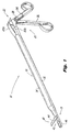
- Fig. 1 depicts an endoscopic surgical rongeur instrument 10 which may be used to remove portions of tissue during an endoscopic discectomy procedure and which is configured to be disassembled for cleaning and reassembled for subsequent utilization.
- proximal refers to a direction of the instrument away from the patient and towards the user while the term “distal” refers to a direction of the instrument towards the patient and away from the user.
- Instrument 10 includes a handle mechanism 20, an elongated endoscopic portion 30 extending from the handle mechanism 20 and a tool mechanism 40 supported at a distal end 31 of endoscopic portion 30.
- Handle mechanism 20 includes a body portion 22 having an upper 22a and a lower 22b body portion, a stationary grip 24 extending from body portion 22 and a pivotable grip 26 pivotally mounted to body portion 22.
- Pivotable grip 26 is detachably mounted to body portion 22 by locking member 28 which will be described in greater detail hereinbelow.
- Endoscopic portion 30 includes a first half-section member 32 and a second half-section member 34 which is preferably removably mounted to the first half-section member 32 and is slidable with respect thereto.
- Tool mechanism 40 includes jaw assembly 42 which in the embodiment of Fig. 1 includes an actuating jaw member 44 and a stationary jaw member 46.
- pivotable grip 26 is pivotally and detachably connected to lower body portion 22b by locking member 28 and is also pivotally mounted within upper body portion 22a.
- Pivotable grip 26 is pivotable about pivot pin 29 which is disposed within a generally semi-circular shaped recess 36(Fig. 7) formed in upper body portion 22a .
- Pivot pin 29 is preferably formed integrally within upper portion 22a, but alternatively may be attached thereto in any suitable manner, for example, by drilling a hole through upper portion 22a and inserting pin 29 therethrough.
- Pivotable grip 26 includes slot 38 disposed at a first end 26a thereof.
- First end 26a extends through tapered cutout 27 formed in lower body portion 22b such that slot 38 is received within recess 36 and engages pivot pin 29. Movement of pivotable grip 26 therefore causes first end 26a to pivot about pivot pin 29 within recess 36, thereby producing reciprocal movement of second half section member 34 as seen in Figs. 7-9.
- locking member 28 includes knob 50 and fastener 54.
- Fastener 54 includes a rod 56, an abutment portion 57 and is preferably of a "T" shape configuration.
- Fastener 54 is configured to be received through a bore 76 formed within first end 26a of pivotable grip 26, and is also received within an extension member 61 which extends from and is preferably formed integral with body portion 22.
- Extension member 61 includes left and right extension arms 62, 64, respectively which have an opening 66 formed therebetween.
- rod 56 of fastener 54 extends through the left and right extension arms 62, 64 and pivotable grip 26.
- Rod 56 also extends from and is at least partially received within channel 53 formed in knob 50.
- Rod 56 is attached to knob 50 by a pin 58 (Fig. 2) which extends into knob 50 and through aperture 60 formed in rod 56.
- Knob 50 is biased in a direction away from body portion 22 by a compression spring 52 which is disposed circumferentially about rod 56.
- Compression spring 52 is received at least partially within channel 53 and is in abutment with an outer surface 70 of left extension arm 62.
- abutment portion 57 rests in shelf 78 (Fig. 4A) of engagement section 77.
- Engagement section 77 includes shelf portion 78 formed in an outer surface 80 of right extension arm 64, and further includes an elongated through-hole 82 extending through right extension arm 64 and preferably intersecting shelf portion 78 at approximately a 90 degree angle.
- Elongated through-hole 82 is configured to receive abutment portion 57 and is preferably a similar shape as abutment portion 57.
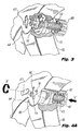
- knob 50 In order to detach pivotable grip 26 from body portion 22, locking member 28 must be disengaged. As shown in Fig. 4A, to disengage locking member 28 from pivotable grip 26, knob 50 is urged in the direction of arrow "A" by the user, against the biasing force of compression spring 52. Urging knob 50 in the direction of arrow “A” causes corresponding movement of fastener 54 in the direction of arrow “A” which results in abutment portion 57 being displaced from shelf portion 78. After abutment portion 57 has been displaced from shelf portion 78, knob 50 is rotated in either a clockwise or counter-clockwise direction as represented by arrow "B", approximately 90 degrees, until abutment portion 57 is in the position shown in Fig. 4B, in substantial alignment with elongated through-hole 82.
- knob 50 is urged in the direction of arrow "C” thereby causing corresponding movement of fastener 54 in the direction of arrow “C". Movement of fastener 54 in the direction of arrow “C” results in abutment portion 57 and rod 56 being moved through right actuation arm 64, via through-hole 82 and into opening 66, thereby disengaging fastener 54 from right actuation arm 64.
- abutment portion 57 and rod 56 continues through bore 76 formed within first end 26a of pivotable grip 26, thereby disengaging fastener 54 from engagement with pivotable grip 26.
- Disengagement of fastener 54 from pivotable grip 26 allows the user to move pivotable grip 26 in the direction of arrow "D" thereby releasing pivotable grip 26 from body portion 22.
- abutment portion 57 is retained within opening 66 within a shelf (not shown) of a similar configuration to shelf 78, formed within inner surface 72 of left extension arm 62.
- endoscopic portion 30 includes first-half section member 32 and second half-section member 34.
- Second half-section member 34 includes an outer surface 34a which preferably has a substantially semi-circular shape and a generally flat inner surface 34b.
- Inner surface 34b includes a plurality of inwardly projecting guide pins 94 having end members 96 which are dimensioned to cooperatively engage corresponding guide slots 84 formed in first half-section member 32, to ensure proper alignment of the first and second half-section members 32, 34 and to permit reciprocal (linear) motion of second half-section member 34 with respect to first half-section member 32 while also preventing disengagement of second half-section member 34 from first half-section member 32.
- actuation portion 98 Extending from and preferably formed integrally with distal end 31b of second-half section member 34 is actuation portion 98 which includes aperture 100 disposed therethrough. Pin 102 is received and secured within aperture 100 and is also slidably disposed within camming slot 104 of pivoting jaw member 44. Pivoting jaw member 44 includes arm 106 preferably formed integrally therewith. Arm 106 is received within generally semi-circular shaped slot 110 formed adjacent the distal end of first half-section member 32. Arm 106 includes aperture 108 formed therein for receipt of pivot pin 112 which extends through aperture 114 disposed adjacent the distal end of first half-section member 32.
- First half-section member 32 includes an outer surface 32a which preferably has a substantially semi-circular shape and a generally flat inner surface 32b which includes a plurality of guide slots 84 formed therein.
- Guide slots 84 each include a first section 86, preferably of a generally oval configuration having a width "w" which is preferably greater than the width of end members 96.
- Guide slots 84 also each include a second section 88 in communication with the first section 86 also preferably having a generally oval configuration.
- Section 88 includes stepped portion 89 which includes a lower portion 91 also having a width "w" and an upper portion “93” having a width "w1" which is preferably smaller than the width of end members 96. Therefore, when assembling instrument 10, guide pins 94 and end members 96 are inserted into first section 86 and then slidably moved in a proximal direction such that end members 96 are disposed and retained within lower portion 91 of stepped portion 89. Extending from and preferably formed integrally with distal end 31a of first-half section member 32 is stationary jaw member 46. Jaw member 46 includes cup section 90 for grasping and removing portions of tissue during an endoscopic discetomy procedure and further includes "V" shaped cutouts 92a and 92b for enhancing the gripping of tissue.
- instrument 10 is inserted into the surgical site via a trocar assembly (not shown) preferably in the position shown in Fig. 7.
- a trocar assembly (not shown) preferably in the position shown in Fig. 7.
- the circular cross-sectional configuration of endoscopic portion 30 formed by the mating of the semi-circular shaped first and second half section members 32, 34 facilitate insertion through the trocar cannula.
- pivotable grip 26 is in a first position with respect to stationary grip 24 and tool mechanism 40 is in an initial position in which jaw member 44 is substantially parallel with respect to jaw member 46.
- slot 38 is in engagement with pivot pin 29 as described hereinabove and guide pins 94 along with end members 96 are disposed in second sections 88 of guide slots 84.
- the user may move pivotable handle in the direction of arrow "F" into a second position (Fig. 8) thereby urging second half-section member 34 in a proximal direction as represented in the drawing by arrow "G".
- second half-section member 34 moves proximally it causes corresponding movement of guide pins 94 along with end members 96 within second section 88 of guide slots 84 to the position shown in Fig. 8.
- Movement of second half-section member 34 in the proximal direction also urges pin 102 proximally which causes pin 102 to ride in camming slot 104 in the direction of arrow "H".
- Pivotable grip 26 has a range of motion which is limited by walls 27a and 27b of preferably tapered cutout 27, therefore, second-half section member 34 in unable to be moved beyond a predetermined proximal position thereby restraining pivoting jaw member 44 from pivoting beyond angle ⁇ which preferably does not exceed approximately 45 degrees.
- pivotable grip 26 is first detached from body portion 22 by disengaging locking member 28 as described hereinabove.
- second half-section member 34 is able to be moved proximally beyond the predetermined proximal position, in the direction represented by arrow "L".
- second half-section member 34 moves proximally it causes guide pins 94 along with end members 96 to be moved into first sections 86 of guide slots 84. Movement of second half-section member 34 also causes pivoting jaw member 44 to open at an angle 1 ⁇ 2 with respect to stationary jaw member 46, which is greater than angle ⁇ .
- second half-section member 34 may be disengaged from first half-section 32 by lifting second half-section member 34 in the direction of arrow "K" and by disengaging pin 102 from camming slot 104.
- pin 102 is inserted into camming slot 104 and guide pins 94 and end members 96 are inserted into first section 86.
- Guide pins 94 and end members 96 are then moved in a proximal direction such that end members 96 are retained within lower portion 91 of stepped portion 89.
- First end 26a of pivotable handle 26 is then inserted through tapered cutout 27 and into recess 36 such that slot 38 of first end 26 engages pivot pin 29.
- Knob 50 is then moved against the force of biasing spring 52 to insert fastener 54 through bore 76 formed within first end 26a of pivotable grip 26 and also through extension member 61, knob 50 is then rotated until abutment portion 57 rests within shelf portion 78.
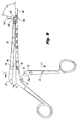
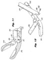
- Instrument 200 is substantially similar to instrument 10 except that jaw assembly 242 includes an angled actuating jaw member 244 and an angled stationary jaw member 246. Angled jaw members 244 and 246 operate in the same fashion as jaw members 44 and 46, but are angularly disposed with respect to endoscopic portion 30 at all times.
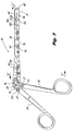
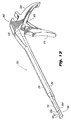
- FIG. 13-16 there is illustrated an endoscopic surgical rongeur instrument 300 which may be used to trim away part of a bone during an endoscopic discectomy procedure and which is configured to be disassembled for cleaning and reassembled for subsequent utilization.
- Instrument 300 is similar to instrument 10 except that tool mechanism 340 includes an upper actuating shaft 302 and a lower stationary shaft 304.
- Actuating shaft 302 extends from and is preferably formed integral with second half-section member 334 while lower stationary shaft 304 extends from and is preferably formed integral with first half-section member 332.
- Stationary shaft 304 includes angular engagement section 309 which cooperates with a distal end 31b of actuation shaft 302.
- Second half-section member 334 is preferably removably mounted to the first half-section member 32 and is slidable with respect thereto as described hereinabove with respect to the embodiment of Fig. 1; except that locking member 328 in the embodiment of Fig. 13 includes knob 350 and rod 356 which is preferably formed integrally therewith and includes a threaded portion 306 which is an alternative to abutment portion 57 of Fig. 1.
- Rod 356 is configured to be received through internally threaded bore 376 formed within first end 326a of pivotable grip 326, and is also received within an extension member 361 which extends from and is preferably formed integral with body portion 322.
- Extension member 361 includes left and right extension arms 362, 364, respectively which have an opening 366 (not shown) formed therebetween. Extension arms 362, 364 each included an internally threaded bore 368 for receipt of rod 356. When instrument 300 is assembled, rod 356 extends into the left and right extension arms 362, 364 and pivotable grip 326.
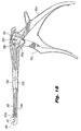
- a piece of bone which is to be removed is placed in gap 311 formed between angular engagement section 309 and distal end 331b of actuation shaft 302.
- Pivotable grip 326 is then moved in the direction of arrow "Z" by the user which causes second half-section member 334 to move proximally in the direction of arrow "Y" relative to first half-section member 332, as described hereinabove with respect to Fig. 1.
- Movement of second half-section member 334 causes corresponding movement of actuating shaft 302 in the direction of arrow "Y” thereby crushing any bone disposed in gap 311 against angular engagement section 309.
- a biasing spring 313 Disposed between pivotable grip 326 and stationary grip 324 is a biasing spring 313 which acts to return pivotable grip 326 to the first position shown in Fig. 13 when pivotable grip 326 is released by the user.
- Instrument 300 is disassembled in a similar manner as described hereinabove with reference to Fig. 1. Disassembly of second half-section member 334 from first half-section member 332 is accomplished by first disengaging spring 313, unscrewing rod 356 from extension member 361 and internally threaded bore 376. Pivotable handle 326 is then removed from body assembly 322 and second half-section member 334 is moved proximally until guide pins 394 and end members 396 extending from second half-section member 334 are be moved into first sections 386 of guide slots 384 formed within first half-section member 332 as described hereinabove with respect to the embodiment of Fig. 1. Second half-section member 334 is then lifted from engagement with first half-section member 332.
Applications Claiming Priority (3)
| Application Number | Priority Date | Filing Date | Title |
|---|---|---|---|
| US320478 | 1981-11-12 | ||
| US32047894A | 1994-10-07 | 1994-10-07 | |
| EP95115806A EP0706780B1 (de) | 1994-10-07 | 1995-10-06 | Chirurgische Instrumente für endoskopische Wirbeleingriffe |
Related Parent Applications (1)
| Application Number | Title | Priority Date | Filing Date |
|---|---|---|---|
| EP95115806A Division EP0706780B1 (de) | 1994-10-07 | 1995-10-06 | Chirurgische Instrumente für endoskopische Wirbeleingriffe |
Publications (3)
| Publication Number | Publication Date |
|---|---|
| EP1224914A2 true EP1224914A2 (de) | 2002-07-24 |
| EP1224914A3 EP1224914A3 (de) | 2004-01-28 |
| EP1224914B1 EP1224914B1 (de) | 2007-12-12 |
Family
ID=23246610
Family Applications (2)
| Application Number | Title | Priority Date | Filing Date |
|---|---|---|---|
| EP02008284A Expired - Lifetime EP1224914B1 (de) | 1994-10-07 | 1995-10-06 | Chirurgische Instrumente für endoskopische Wirbelsäuleneingriffe |
| EP95115806A Expired - Lifetime EP0706780B1 (de) | 1994-10-07 | 1995-10-06 | Chirurgische Instrumente für endoskopische Wirbeleingriffe |
Family Applications After (1)
| Application Number | Title | Priority Date | Filing Date |
|---|---|---|---|
| EP95115806A Expired - Lifetime EP0706780B1 (de) | 1994-10-07 | 1995-10-06 | Chirurgische Instrumente für endoskopische Wirbeleingriffe |
Country Status (5)
| Country | Link |
|---|---|
| US (1) | US5851214A (de) |
| EP (2) | EP1224914B1 (de) |
| KR (1) | KR960013329A (de) |
| CA (1) | CA2159685C (de) |
| DE (2) | DE69529791T2 (de) |
Cited By (3)
| Publication number | Priority date | Publication date | Assignee | Title |
|---|---|---|---|---|
| CN107961054A (zh) * | 2017-12-11 | 2018-04-27 | 美茵(北京)医疗器械研发有限公司 | 拆装方便的微创止血钳 |
| WO2021144783A3 (en) * | 2020-06-12 | 2021-10-21 | Inno4Spine Ag | Rongeur for tissue removal |
| WO2023038821A1 (en) * | 2021-09-07 | 2023-03-16 | Life Spine, Inc. | Medical instrument for dislodging vertebral disc material from a vertebral disc in a vertebral disc space via a cannula |
Families Citing this family (126)
| Publication number | Priority date | Publication date | Assignee | Title |
|---|---|---|---|---|
| EP1230902A1 (de) | 1996-11-15 | 2002-08-14 | Advanced Bio Surfaces, Inc. | Biomateralsystem für in-situ Gewebewiederherstellung |
| DE69729543T2 (de) * | 1997-01-08 | 2004-11-04 | Atlantech Medical Devices Ltd. | Endoskopische Schneidvorrichtung |
| DE19702079A1 (de) * | 1997-01-22 | 1998-07-23 | Aesculap Ag & Co Kg | Chirurgisches Instrument |
| US6175758B1 (en) | 1997-07-15 | 2001-01-16 | Parviz Kambin | Method for percutaneous arthroscopic disc removal, bone biopsy and fixation of the vertebrae |
| DE19748369C2 (de) * | 1997-11-03 | 2003-08-21 | Medi Plus Instr Gmbh & Co Kg | Chirurgisches Schiebeschaftinstrument |
| DE19802145C1 (de) | 1998-01-22 | 1999-09-30 | Storz Karl Gmbh & Co | Medizinisches Schiebeschaftinstrument |
| FR2778084B1 (fr) | 1998-04-29 | 2000-09-15 | Soprane Sa | Dispositif de liaison pour instrument chirurgical |
| FR2780630B1 (fr) * | 1998-07-03 | 2000-09-15 | Soprane Sa | Instrument chirurgical et son dispositif de liaison permettant, suivant des positions angulaires determinees et independantes, le montage et/ou le demontage rapide de l'element mobile de coupe et de sa poignee d'actionnement |
| US6652553B2 (en) * | 1998-08-20 | 2003-11-25 | Endius Incorporated | Surgical tool for use in expanding a cannula |
| US7682370B2 (en) * | 1998-08-20 | 2010-03-23 | Zimmer Spine, Inc. | Surgical tool for use in expanding a cannula |
| US6187000B1 (en) | 1998-08-20 | 2001-02-13 | Endius Incorporated | Cannula for receiving surgical instruments |
| US7799036B2 (en) | 1998-08-20 | 2010-09-21 | Zimmer Spine, Inc. | Method and apparatus for securing vertebrae |
| US7641670B2 (en) * | 1998-08-20 | 2010-01-05 | Zimmer Spine, Inc. | Cannula for receiving surgical instruments |
| US7364577B2 (en) | 2002-02-11 | 2008-04-29 | Sherwood Services Ag | Vessel sealing system |
| US20030088268A1 (en) * | 1999-12-17 | 2003-05-08 | Harald Weinmann | Surgical sliding shaft instrument |
| WO2001050973A1 (en) * | 1999-12-24 | 2001-07-19 | Lee Hee Young | Mandibular angle fracture operating method and its devices |
| US6358268B1 (en) | 2000-03-06 | 2002-03-19 | Robert B. Hunt | Surgical instrument |
| US6506208B2 (en) | 2000-03-06 | 2003-01-14 | Robert B. Hunt | Surgical instrument |
| US7056321B2 (en) | 2000-08-01 | 2006-06-06 | Endius, Incorporated | Method of securing vertebrae |
| AU2001288462A1 (en) | 2000-08-30 | 2002-03-13 | Cerebral Vascular Applications Inc. | Medical instrument |
| US6702820B2 (en) * | 2000-10-24 | 2004-03-09 | John B. Mazur | Surgical cutting instrument having concative jaw tips |
| US6517545B1 (en) * | 2000-10-24 | 2003-02-11 | John B. Mazur | Surgical cutting instrument having concave jaw tips |
| DE10060769C2 (de) * | 2000-12-07 | 2003-07-24 | Storz Karl Gmbh & Co Kg | Medizinisches Instrument |
| DE10111510B4 (de) * | 2001-03-09 | 2007-01-11 | Richard Wolf Gmbh | Chirurgische Zange |
| US7473253B2 (en) | 2001-04-06 | 2009-01-06 | Covidien Ag | Vessel sealer and divider with non-conductive stop members |
| US7144393B2 (en) | 2001-05-15 | 2006-12-05 | Dipoto Gene P | Structure for receiving surgical instruments |
| US7041084B2 (en) | 2001-05-24 | 2006-05-09 | Fojtik Shawn P | Hand-held, hand operated power syringe and methods |
| US6755338B2 (en) * | 2001-08-29 | 2004-06-29 | Cerebral Vascular Applications, Inc. | Medical instrument |
| US6991633B2 (en) * | 2001-10-10 | 2006-01-31 | Codman & Shurtleff, Inc. | Rongeur with detachable crossbar |
| US6638280B2 (en) * | 2001-10-10 | 2003-10-28 | Codman & Shurtleff, Inc. | Rongeur with drainage |
| US6685710B2 (en) | 2001-10-10 | 2004-02-03 | Codman & Shurtleff, Inc. | Rongeur with detachable crossbar |
| US7588585B2 (en) * | 2002-03-26 | 2009-09-15 | Novare Surgical Systems, Inc. | Handleless clamping device |
| US7931649B2 (en) | 2002-10-04 | 2011-04-26 | Tyco Healthcare Group Lp | Vessel sealing instrument with electrical cutting mechanism |
| US8162966B2 (en) | 2002-10-25 | 2012-04-24 | Hydrocision, Inc. | Surgical devices incorporating liquid jet assisted tissue manipulation and methods for their use |
| US10363061B2 (en) | 2002-10-25 | 2019-07-30 | Hydrocision, Inc. | Nozzle assemblies for liquid jet surgical instruments and surgical instruments for employing the nozzle assemblies |
| US7799026B2 (en) | 2002-11-14 | 2010-09-21 | Covidien Ag | Compressible jaw configuration with bipolar RF output electrodes for soft tissue fusion |
| US7112204B2 (en) * | 2003-02-06 | 2006-09-26 | Medicinelodge, Inc. | Tibial tubercle osteotomy for total knee arthroplasty and instruments and implants therefor |
| US8714429B2 (en) * | 2003-04-29 | 2014-05-06 | Covidien Lp | Dissecting tip for surgical stapler |
| EP1617778A2 (de) | 2003-05-01 | 2006-01-25 | Sherwood Services AG | Elektrochirurgisches instrument zur verringerung von hitzebedingten schäden an benachbartem gewebe |
| US7976464B2 (en) | 2003-08-26 | 2011-07-12 | Zimmer Spine, Inc. | Access systems and methods for minimally invasive surgery |
| US7226451B2 (en) | 2003-08-26 | 2007-06-05 | Shluzas Alan E | Minimally invasive access device and method |
| US9848938B2 (en) | 2003-11-13 | 2017-12-26 | Covidien Ag | Compressible jaw configuration with bipolar RF output electrodes for soft tissue fusion |
| US7367976B2 (en) | 2003-11-17 | 2008-05-06 | Sherwood Services Ag | Bipolar forceps having monopolar extension |
| US7131970B2 (en) | 2003-11-19 | 2006-11-07 | Sherwood Services Ag | Open vessel sealing instrument with cutting mechanism |
| DE102004009200A1 (de) * | 2004-02-25 | 2005-09-15 | Karl Storz Gmbh & Co. Kg | Chirurgisches Schaftinstrument für endoskopischen Einsatz |
| US7611517B2 (en) * | 2004-02-27 | 2009-11-03 | Warsaw Orthopedic, Inc. | Rod reducer |
| US7780662B2 (en) | 2004-03-02 | 2010-08-24 | Covidien Ag | Vessel sealing system using capacitive RF dielectric heating |
| US20050251196A1 (en) * | 2004-05-06 | 2005-11-10 | Endius Incorporated | Surgical tool for use in expanding a tubular structure |
| US7578819B2 (en) | 2005-05-16 | 2009-08-25 | Baxano, Inc. | Spinal access and neural localization |
| US8430881B2 (en) | 2004-10-15 | 2013-04-30 | Baxano, Inc. | Mechanical tissue modification devices and methods |
| US9247952B2 (en) | 2004-10-15 | 2016-02-02 | Amendia, Inc. | Devices and methods for tissue access |
| US20100331883A1 (en) | 2004-10-15 | 2010-12-30 | Schmitz Gregory P | Access and tissue modification systems and methods |
| WO2006044727A2 (en) | 2004-10-15 | 2006-04-27 | Baxano, Inc. | Devices and methods for tissue removal |
| US7938830B2 (en) | 2004-10-15 | 2011-05-10 | Baxano, Inc. | Powered tissue modification devices and methods |
| US8257356B2 (en) | 2004-10-15 | 2012-09-04 | Baxano, Inc. | Guidewire exchange systems to treat spinal stenosis |
| US20110190772A1 (en) | 2004-10-15 | 2011-08-04 | Vahid Saadat | Powered tissue modification devices and methods |
| US7857813B2 (en) | 2006-08-29 | 2010-12-28 | Baxano, Inc. | Tissue access guidewire system and method |
| US7887538B2 (en) | 2005-10-15 | 2011-02-15 | Baxano, Inc. | Methods and apparatus for tissue modification |
| US7959577B2 (en) | 2007-09-06 | 2011-06-14 | Baxano, Inc. | Method, system, and apparatus for neural localization |
| US8617163B2 (en) | 2004-10-15 | 2013-12-31 | Baxano Surgical, Inc. | Methods, systems and devices for carpal tunnel release |
| US8048080B2 (en) | 2004-10-15 | 2011-11-01 | Baxano, Inc. | Flexible tissue rasp |
| US7738969B2 (en) | 2004-10-15 | 2010-06-15 | Baxano, Inc. | Devices and methods for selective surgical removal of tissue |
| US8062300B2 (en) | 2006-05-04 | 2011-11-22 | Baxano, Inc. | Tissue removal with at least partially flexible devices |
| US9101386B2 (en) | 2004-10-15 | 2015-08-11 | Amendia, Inc. | Devices and methods for treating tissue |
| US7738968B2 (en) | 2004-10-15 | 2010-06-15 | Baxano, Inc. | Devices and methods for selective surgical removal of tissue |
| US8221397B2 (en) | 2004-10-15 | 2012-07-17 | Baxano, Inc. | Devices and methods for tissue modification |
| US7909823B2 (en) | 2005-01-14 | 2011-03-22 | Covidien Ag | Open vessel sealing instrument |
| US20070055259A1 (en) * | 2005-08-17 | 2007-03-08 | Norton Britt K | Apparatus and methods for removal of intervertebral disc tissues |
| US7879035B2 (en) | 2005-09-30 | 2011-02-01 | Covidien Ag | Insulating boot for electrosurgical forceps |
| US7922953B2 (en) | 2005-09-30 | 2011-04-12 | Covidien Ag | Method for manufacturing an end effector assembly |
| EP1769765B1 (de) | 2005-09-30 | 2012-03-21 | Covidien AG | Isolierhülse für elektrochirurgische Zange |
| CA2561034C (en) | 2005-09-30 | 2014-12-09 | Sherwood Services Ag | Flexible endoscopic catheter with an end effector for coagulating and transfecting tissue |
| US20080051812A1 (en) * | 2006-08-01 | 2008-02-28 | Baxano, Inc. | Multi-Wire Tissue Cutter |
| US8062298B2 (en) | 2005-10-15 | 2011-11-22 | Baxano, Inc. | Flexible tissue removal devices and methods |
| US8092456B2 (en) | 2005-10-15 | 2012-01-10 | Baxano, Inc. | Multiple pathways for spinal nerve root decompression from a single access point |
| US8366712B2 (en) | 2005-10-15 | 2013-02-05 | Baxano, Inc. | Multiple pathways for spinal nerve root decompression from a single access point |
| US20070123933A1 (en) * | 2005-11-29 | 2007-05-31 | Ethicon Endo-Surgery, Inc. | Manually operable equipment |
| US20070162062A1 (en) * | 2005-12-08 | 2007-07-12 | Norton Britt K | Reciprocating apparatus and methods for removal of intervertebral disc tissues |
| US8092536B2 (en) | 2006-05-24 | 2012-01-10 | Disc Dynamics, Inc. | Retention structure for in situ formation of an intervertebral prosthesis |
| US20080021278A1 (en) * | 2006-07-24 | 2008-01-24 | Leonard Robert F | Surgical device with removable end effector |
| US20080098564A1 (en) * | 2006-10-24 | 2008-05-01 | Fojtik Shawn P | Locking Hinges for Syringe Handles, Syringes Including Locking Hinges, and Associated Methods |
| US8672893B2 (en) | 2007-10-23 | 2014-03-18 | Control Medical Technology, Llc | Syringe with rotatable element, aspiration systems including the syringe, and associated methods |
| US10058656B2 (en) | 2006-10-24 | 2018-08-28 | Pmt Partners, Llc | Syringe with rotatable element, systems including the syringe, and associated methods |
| US11191931B2 (en) | 2007-10-01 | 2021-12-07 | Pmt Partners, Llc | Methods for manually injecting/aspirating fluids through small diameter catheters and needles and manual injection/aspiration systems including small diameter catheters and needles |
| US20090088702A1 (en) * | 2007-10-01 | 2009-04-02 | Fojtik Shawn P | Methods for manually injecting/aspirating fluids through small diameter catheters and needles and manual injection/aspiration systems including small diameter catheters and needles |
| KR100877916B1 (ko) * | 2007-10-15 | 2009-01-12 | 양두병 | 성형수술용 의료기구 |
| US8192436B2 (en) | 2007-12-07 | 2012-06-05 | Baxano, Inc. | Tissue modification devices |
| DE202008001675U1 (de) | 2008-02-06 | 2008-04-17 | Weinmann Gmbh, Chirurgische Instrumente | Zerlegbares chirurgisches Instrument |
| US8409206B2 (en) | 2008-07-01 | 2013-04-02 | Baxano, Inc. | Tissue modification devices and methods |
| US9314253B2 (en) | 2008-07-01 | 2016-04-19 | Amendia, Inc. | Tissue modification devices and methods |
| US8398641B2 (en) | 2008-07-01 | 2013-03-19 | Baxano, Inc. | Tissue modification devices and methods |
| MX348805B (es) | 2008-07-14 | 2017-06-28 | Baxano Inc | Dispositivo de modificación de tejidos. |
| US8142473B2 (en) | 2008-10-03 | 2012-03-27 | Tyco Healthcare Group Lp | Method of transferring rotational motion in an articulating surgical instrument |
| US8016827B2 (en) | 2008-10-09 | 2011-09-13 | Tyco Healthcare Group Lp | Apparatus, system, and method for performing an electrosurgical procedure |
| US8114122B2 (en) | 2009-01-13 | 2012-02-14 | Tyco Healthcare Group Lp | Apparatus, system, and method for performing an electrosurgical procedure |
| US8936598B2 (en) * | 2009-01-14 | 2015-01-20 | DePuy Synthes Products, LLC | Spinal disc preparation tool |
| MX2011009165A (es) | 2009-03-13 | 2011-09-26 | Baxano Inc | Dispositivo y metodos de localizacion neural flexibles. |
| US8187273B2 (en) | 2009-05-07 | 2012-05-29 | Tyco Healthcare Group Lp | Apparatus, system, and method for performing an electrosurgical procedure |
| US8394102B2 (en) | 2009-06-25 | 2013-03-12 | Baxano, Inc. | Surgical tools for treatment of spinal stenosis |
| US8246618B2 (en) | 2009-07-08 | 2012-08-21 | Tyco Healthcare Group Lp | Electrosurgical jaws with offset knife |
| EP2451403B1 (de) | 2009-07-09 | 2016-04-27 | R Tree Innovations, LLC | Anordnung zum Einsetzen eines Zwischenwirbel-Implantats |
| US8133254B2 (en) | 2009-09-18 | 2012-03-13 | Tyco Healthcare Group Lp | In vivo attachable and detachable end effector assembly and laparoscopic surgical instrument and methods therefor |
| US8112871B2 (en) | 2009-09-28 | 2012-02-14 | Tyco Healthcare Group Lp | Method for manufacturing electrosurgical seal plates |
| US9113940B2 (en) | 2011-01-14 | 2015-08-25 | Covidien Lp | Trigger lockout and kickback mechanism for surgical instruments |
| CN102670156A (zh) * | 2011-03-09 | 2012-09-19 | 上海菲捷实业有限公司 | 一种净化式医用内窥镜 |
| DE102011107178A1 (de) * | 2011-07-13 | 2013-01-17 | Karl Storz Gmbh & Co. Kg | Medizinisches Schneidinstrument zum Schneiden von Muskeln und Sehnen |
| USD680220S1 (en) | 2012-01-12 | 2013-04-16 | Coviden IP | Slider handle for laparoscopic device |
| DE202012001348U1 (de) * | 2012-02-13 | 2012-03-12 | Waldemar Link Gmbh & Co. Kg | Zerlegbares chirurgisches Schiebeschaftinstrument |
| CN102614005B (zh) * | 2012-04-06 | 2014-08-13 | 上海医疗器械(集团)有限公司手术器械厂 | 滑板式手术器械 |
| US9510891B2 (en) | 2012-06-26 | 2016-12-06 | Covidien Lp | Surgical instruments with structures to provide access for cleaning |
| JP6258935B2 (ja) | 2012-08-03 | 2018-01-10 | ボス・インストゥルメンツ・リミテッド | プッシュボタン式骨鉗子 |
| US10507027B2 (en) | 2012-08-03 | 2019-12-17 | Boss Instruments, Ltd., Inc. | Push button rongeur |
| US8529580B1 (en) * | 2012-11-01 | 2013-09-10 | Hasan M. Sh. Sh. Alshemari | Surgical grasping instrument with U-shaped jaws in combination with a tympanostomy tube |
| US10314605B2 (en) | 2014-07-08 | 2019-06-11 | Benvenue Medical, Inc. | Apparatus and methods for disrupting intervertebral disc tissue |
| US10987469B2 (en) | 2014-09-25 | 2021-04-27 | Pmt Partners, Llc | Rotatable finger loop for syringe, syringe configured to receive the rotatable finger loop and associated methods |
| US10022243B2 (en) | 2015-02-06 | 2018-07-17 | Benvenue Medical, Inc. | Graft material injector system and method |
| US10925618B2 (en) * | 2015-04-16 | 2021-02-23 | Steribite, LLC | Rongeur with a disposable attribute |
| WO2017031712A1 (en) | 2015-08-26 | 2017-03-02 | Covidien Lp | Electrosurgical end effector assemblies and electrosurgical forceps configured to reduce thermal spread |
| DE202015006833U1 (de) * | 2015-09-29 | 2015-10-22 | Christoph Zepf | Knochenstanze mit unverlierbarem Stanzschieber |
| US10213250B2 (en) | 2015-11-05 | 2019-02-26 | Covidien Lp | Deployment and safety mechanisms for surgical instruments |
| WO2018049078A1 (en) * | 2016-09-07 | 2018-03-15 | Vertos Medical, Inc. | Percutaneous lateral recess resection methods and instruments |
| US10758286B2 (en) | 2017-03-22 | 2020-09-01 | Benvenue Medical, Inc. | Minimal impact access system to disc space |
| CN107713962A (zh) * | 2017-11-14 | 2018-02-23 | 中南大学湘雅三医院 | 腔镜器械手柄旋转调节装置 |
| US11583327B2 (en) | 2018-01-29 | 2023-02-21 | Spinal Elements, Inc. | Minimally invasive interbody fusion |
| WO2019178575A1 (en) | 2018-03-16 | 2019-09-19 | Benvenue Medical, Inc. | Articulated instrumentation and methods of using the same |
| US11331144B2 (en) | 2018-05-04 | 2022-05-17 | Covidien Lp | Light energy surgical system, apparatus, and method |
Citations (7)
| Publication number | Priority date | Publication date | Assignee | Title |
|---|---|---|---|---|
| US4545374A (en) | 1982-09-03 | 1985-10-08 | Jacobson Robert E | Method and instruments for performing a percutaneous lumbar diskectomy |
| USRE33258E (en) | 1984-07-23 | 1990-07-10 | Surgical Dynamics Inc. | Irrigating, cutting and aspirating system for percutaneous surgery |
| US5195541A (en) | 1991-10-18 | 1993-03-23 | Obenchain Theodore G | Method of performing laparoscopic lumbar discectomy |
| US5242439A (en) | 1990-01-12 | 1993-09-07 | Laserscope | Means for inserting instrumentation for a percutaneous diskectomy using a laser |
| US5273519A (en) | 1990-11-02 | 1993-12-28 | Tibor Koros | Bongeur surgical instrument |
| US5308358A (en) | 1992-08-25 | 1994-05-03 | Bond Albert L | Rigid-shaft surgical instruments that can be disassembled for improved cleaning |
| US5313962A (en) | 1991-10-18 | 1994-05-24 | Obenchain Theodore G | Method of performing laparoscopic lumbar discectomy |
Family Cites Families (30)
| Publication number | Priority date | Publication date | Assignee | Title |
|---|---|---|---|---|
| FR381096A (fr) * | 1907-08-23 | 1907-12-27 | Victor Marin Y Corrale | Appareil pour l'intubation du larynx |
| US3814102A (en) * | 1972-10-12 | 1974-06-04 | B Thal | Surgical instrument |
| US4084594A (en) * | 1976-10-08 | 1978-04-18 | American Hospital Supply Corporation | Surgical instrument and handle assembly therefor |
| US4122856A (en) * | 1976-10-08 | 1978-10-31 | American Hospital Supply Corporation | Surgical instrument and method of assembly thereof |
| US4201213A (en) * | 1978-01-30 | 1980-05-06 | Codman & Shurtleff, Inc. | Surgical tool |
| DE2808911C2 (de) * | 1978-03-02 | 1979-11-08 | B. Braun Melsungen Ag, 3508 Melsungen | Stanze zum Abtragen von Knochen und Knorpel |
| GB2022421B (en) * | 1978-06-08 | 1982-09-15 | Wolf Gmbh Richard | Devices for obtaining tissure samples |
| US4243047A (en) * | 1979-02-07 | 1981-01-06 | Auburn Enterprises, Inc. | Instrument for taking tissue specimens |
| US4440170A (en) * | 1979-03-06 | 1984-04-03 | Ethicon, Inc. | Surgical clip applying instrument |
| US4369788A (en) * | 1980-01-31 | 1983-01-25 | Goald Harold J | Reversed forceps for microdisc surgery |
| DE8316034U1 (de) * | 1983-06-01 | 1983-09-29 | Richard Wolf Gmbh, 7134 Knittlingen | Scherengriff für austauschbare Zangeneinsätze |
| US4722338A (en) * | 1983-12-12 | 1988-02-02 | Daniel Farley | Medical instrument for removing bone |
| US4777948A (en) * | 1984-01-16 | 1988-10-18 | Wright David W | Surgical tool |
| US4733663A (en) * | 1986-07-02 | 1988-03-29 | Farley Daniel K | Medical instrument for removing bone |
| US4990148A (en) * | 1989-01-13 | 1991-02-05 | Codman & Shurtleff, Inc. | Thin footplate rongeur |
| US5451227A (en) * | 1989-04-24 | 1995-09-19 | Michaelson; Gary K. | Thin foot plate multi bite rongeur |
| US5009661A (en) * | 1989-04-24 | 1991-04-23 | Michelson Gary K | Protective mechanism for surgical rongeurs |
| US5026375A (en) * | 1989-10-25 | 1991-06-25 | Origin Medsystems, Inc. | Surgical cutting instrument |
| US5176699A (en) * | 1991-06-05 | 1993-01-05 | Harold Markham | Surgical device with double jaw actuation |
| US5269797A (en) * | 1991-09-12 | 1993-12-14 | Meditron Devices, Inc. | Cervical discectomy instruments |
| WO1994000059A1 (en) * | 1992-06-24 | 1994-01-06 | Microsurge, Inc. | Reusable endoscopic surgical instrument |
| US5368606A (en) * | 1992-07-02 | 1994-11-29 | Marlow Surgical Technologies, Inc. | Endoscopic instrument system |
| US5282800A (en) * | 1992-09-18 | 1994-02-01 | Edward Weck, Inc. | Surgical instrument |
| US5342391A (en) * | 1992-10-06 | 1994-08-30 | Linvatec Corporation | Cleanable endoscopic surgical instrument |
| US5304203A (en) * | 1992-10-20 | 1994-04-19 | Numed Technologies, Inc. | Tissue extracting forceps for laparoscopic surgery |
| US5312407A (en) * | 1992-12-28 | 1994-05-17 | Carter L Philip | Rongeur apparatus having an offset bayonet and method of use with microscope during microsurgery |
| US5385570A (en) * | 1993-01-12 | 1995-01-31 | R. J. Surgical Instruments, Inc. | Surgical cutting instrument |
| DE9307621U1 (de) * | 1993-05-19 | 1993-07-22 | Aesculap Ag, 78532 Tuttlingen, De | |
| US5336238A (en) * | 1993-07-19 | 1994-08-09 | Birtcher Medical Systems, Inc. | Surgical instrument capable of disassembly |
| DE4341734C1 (de) * | 1993-12-08 | 1994-09-29 | Aesculap Ag | Instrument für chirurgische Zwecke |
-
1995
- 1995-10-02 CA CA002159685A patent/CA2159685C/en not_active Expired - Fee Related
- 1995-10-06 EP EP02008284A patent/EP1224914B1/de not_active Expired - Lifetime
- 1995-10-06 EP EP95115806A patent/EP0706780B1/de not_active Expired - Lifetime
- 1995-10-06 DE DE69529791T patent/DE69529791T2/de not_active Expired - Lifetime
- 1995-10-06 DE DE69535666T patent/DE69535666T2/de not_active Expired - Lifetime
- 1995-10-07 KR KR1019950034623A patent/KR960013329A/ko not_active Application Discontinuation
-
1996
- 1996-09-16 US US08/713,091 patent/US5851214A/en not_active Expired - Lifetime
Patent Citations (7)
| Publication number | Priority date | Publication date | Assignee | Title |
|---|---|---|---|---|
| US4545374A (en) | 1982-09-03 | 1985-10-08 | Jacobson Robert E | Method and instruments for performing a percutaneous lumbar diskectomy |
| USRE33258E (en) | 1984-07-23 | 1990-07-10 | Surgical Dynamics Inc. | Irrigating, cutting and aspirating system for percutaneous surgery |
| US5242439A (en) | 1990-01-12 | 1993-09-07 | Laserscope | Means for inserting instrumentation for a percutaneous diskectomy using a laser |
| US5273519A (en) | 1990-11-02 | 1993-12-28 | Tibor Koros | Bongeur surgical instrument |
| US5195541A (en) | 1991-10-18 | 1993-03-23 | Obenchain Theodore G | Method of performing laparoscopic lumbar discectomy |
| US5313962A (en) | 1991-10-18 | 1994-05-24 | Obenchain Theodore G | Method of performing laparoscopic lumbar discectomy |
| US5308358A (en) | 1992-08-25 | 1994-05-03 | Bond Albert L | Rigid-shaft surgical instruments that can be disassembled for improved cleaning |
Cited By (3)
| Publication number | Priority date | Publication date | Assignee | Title |
|---|---|---|---|---|
| CN107961054A (zh) * | 2017-12-11 | 2018-04-27 | 美茵(北京)医疗器械研发有限公司 | 拆装方便的微创止血钳 |
| WO2021144783A3 (en) * | 2020-06-12 | 2021-10-21 | Inno4Spine Ag | Rongeur for tissue removal |
| WO2023038821A1 (en) * | 2021-09-07 | 2023-03-16 | Life Spine, Inc. | Medical instrument for dislodging vertebral disc material from a vertebral disc in a vertebral disc space via a cannula |
Also Published As
| Publication number | Publication date |
|---|---|
| DE69529791D1 (de) | 2003-04-10 |
| EP1224914A3 (de) | 2004-01-28 |
| EP0706780A3 (de) | 1996-07-03 |
| EP1224914B1 (de) | 2007-12-12 |
| DE69529791T2 (de) | 2003-11-13 |
| EP0706780A2 (de) | 1996-04-17 |
| DE69535666D1 (de) | 2008-01-24 |
| DE69535666T2 (de) | 2008-10-30 |
| US5851214A (en) | 1998-12-22 |
| EP0706780B1 (de) | 2003-03-05 |
| KR960013329A (ko) | 1996-05-22 |
| CA2159685A1 (en) | 1996-04-08 |
| CA2159685C (en) | 2007-07-31 |
Similar Documents
| Publication | Publication Date | Title |
|---|---|---|
| EP1224914B1 (de) | Chirurgische Instrumente für endoskopische Wirbelsäuleneingriffe | |
| CA2144211C (en) | Surgical instruments useful for endoscopic spinal procedures | |
| US5755732A (en) | Surgical instruments useful for endoscopic spinal procedures | |
| US5785647A (en) | Surgical instruments useful for spinal surgery | |
| US9622735B2 (en) | Method for securing vertebrae | |
| JP4223812B2 (ja) | 経皮的外科手術用装置及び方法 | |
| US7226451B2 (en) | Minimally invasive access device and method | |
| US8398649B2 (en) | Articulating transforaminal lumbar interbody fusion inserter device and associated method of use | |
| EP2618752B1 (de) | Laparoskopisches instrument mit befestigbarem greiforgan | |
| JPH06296620A (ja) | 関節鏡下の脊椎手術用装置及び該装置を用いた脊椎手術方法 | |
| US20030083666A1 (en) | Methods and instruments for laparoscopic spinal surgery | |
| US20060195017A1 (en) | Expandable device for providing access to the spine | |
| US11471145B2 (en) | Articulated instrumentation and methods of using the same | |
| US11317934B2 (en) | Percutaneous lateral recess resection methods and instruments | |
| AU2001240091A1 (en) | Methods and instruments for laparoscopic spinal surgery | |
| JP2023504700A (ja) | ドライバ固有バックアウト防止のための装置 | |
| US20220273169A1 (en) | Single-port spinal surgery instrument set and method for using single-port spinal surgery instrument set | |
| WO2021144783A2 (en) | Rongeur for tissue removal |
Legal Events
| Date | Code | Title | Description |
|---|---|---|---|
| PUAI | Public reference made under article 153(3) epc to a published international application that has entered the european phase |
Free format text: ORIGINAL CODE: 0009012 |
|
| 17P | Request for examination filed |
Effective date: 20020422 |
|
| AC | Divisional application: reference to earlier application |
Ref document number: 706780 Country of ref document: EP |
|
| AK | Designated contracting states |
Kind code of ref document: A2 Designated state(s): DE FR GB IT |
|
| PUAL | Search report despatched |
Free format text: ORIGINAL CODE: 0009013 |
|
| AK | Designated contracting states |
Kind code of ref document: A3 Designated state(s): DE FR GB IT |
|
| AKX | Designation fees paid |
Designated state(s): DE FR GB IT |
|
| GRAP | Despatch of communication of intention to grant a patent |
Free format text: ORIGINAL CODE: EPIDOSNIGR1 |
|
| GRAS | Grant fee paid |
Free format text: ORIGINAL CODE: EPIDOSNIGR3 |
|
| GRAA | (expected) grant |
Free format text: ORIGINAL CODE: 0009210 |
|
| AC | Divisional application: reference to earlier application |
Ref document number: 0706780 Country of ref document: EP Kind code of ref document: P |
|
| AK | Designated contracting states |
Kind code of ref document: B1 Designated state(s): DE FR GB IT |
|
| REG | Reference to a national code |
Ref country code: GB Ref legal event code: FG4D |
|
| REF | Corresponds to: |
Ref document number: 69535666 Country of ref document: DE Date of ref document: 20080124 Kind code of ref document: P |
|
| ET | Fr: translation filed | ||
| PLBE | No opposition filed within time limit |
Free format text: ORIGINAL CODE: 0009261 |
|
| STAA | Information on the status of an ep patent application or granted ep patent |
Free format text: STATUS: NO OPPOSITION FILED WITHIN TIME LIMIT |
|
| 26N | No opposition filed |
Effective date: 20080915 |
|
| PGFP | Annual fee paid to national office [announced via postgrant information from national office to epo] |
Ref country code: DE Payment date: 20101027 Year of fee payment: 16 |
|
| PGFP | Annual fee paid to national office [announced via postgrant information from national office to epo] |
Ref country code: IT Payment date: 20101028 Year of fee payment: 16 Ref country code: GB Payment date: 20101025 Year of fee payment: 16 |
|
| PGFP | Annual fee paid to national office [announced via postgrant information from national office to epo] |
Ref country code: FR Payment date: 20111028 Year of fee payment: 17 |
|
| GBPC | Gb: european patent ceased through non-payment of renewal fee |
Effective date: 20121006 |
|
| REG | Reference to a national code |
Ref country code: FR Ref legal event code: ST Effective date: 20130628 |
|
| PG25 | Lapsed in a contracting state [announced via postgrant information from national office to epo] |
Ref country code: GB Free format text: LAPSE BECAUSE OF NON-PAYMENT OF DUE FEES Effective date: 20121006 Ref country code: DE Free format text: LAPSE BECAUSE OF NON-PAYMENT OF DUE FEES Effective date: 20130501 |
|
| REG | Reference to a national code |
Ref country code: DE Ref legal event code: R119 Ref document number: 69535666 Country of ref document: DE Effective date: 20130501 |
|
| PG25 | Lapsed in a contracting state [announced via postgrant information from national office to epo] |
Ref country code: IT Free format text: LAPSE BECAUSE OF NON-PAYMENT OF DUE FEES Effective date: 20121006 Ref country code: FR Free format text: LAPSE BECAUSE OF NON-PAYMENT OF DUE FEES Effective date: 20121031 |