EP1224866A1 - Rolling pin with counterweighted eccentric handles - Google Patents
Rolling pin with counterweighted eccentric handles Download PDFInfo
- Publication number
- EP1224866A1 EP1224866A1 EP01116448A EP01116448A EP1224866A1 EP 1224866 A1 EP1224866 A1 EP 1224866A1 EP 01116448 A EP01116448 A EP 01116448A EP 01116448 A EP01116448 A EP 01116448A EP 1224866 A1 EP1224866 A1 EP 1224866A1
- Authority
- EP
- European Patent Office
- Prior art keywords
- roller
- handles
- rolling device
- handle
- axis
- Prior art date
- Legal status (The legal status is an assumption and is not a legal conclusion. Google has not performed a legal analysis and makes no representation as to the accuracy of the status listed.)
- Granted
Links
Images


Classifications
-
- A—HUMAN NECESSITIES
- A21—BAKING; EDIBLE DOUGHS
- A21C—MACHINES OR EQUIPMENT FOR MAKING OR PROCESSING DOUGHS; HANDLING BAKED ARTICLES MADE FROM DOUGH
- A21C3/00—Machines or apparatus for shaping batches of dough before subdivision
- A21C3/02—Dough-sheeters; Rolling-machines; Rolling-pins
- A21C3/021—Rolling-pins; Hand-operated spreading or rolling devices
Definitions
- the flattening removes material from the handles, causing them to be mounted eccentrically relative to the axis of rotation of the roller so that, in the at-rest position, the heavier bottoms of the handles rotate downwardly so that the flattened surfaces face upwardly.
- the user must first rotate the handles 180° to a use position wherein the flattened surfaces face downwardly, so as to provide more clearance for the user's fingers which are curled beneath the handles.
- the rolling pin 10 includes two handles 30, 30A which, with one exception, are substantially identical in construction. Thus, only the handle 30A will be described in detail.
- the handle 30A has a solid elongated body 31, which may be formed of a suitable plastic material, and is provided at one end with a flat, substantially circular end surface 32, and has a rounded, convex upper surface 33 and a substantially flattened lower surface 34, the body 31 terminating at a tapered, rounded distal end 35.
- a counterbored hole or opening 36 which may be generally oval in transverse cross section, to facilitate hanging the rolling pin 10 on a hook or the like.
- the handle 30 is identical, except that it does not include the hole 36.
- the handles 30 may be prefabricated on the rods 41, 41A, as by insert molding.
- the inner ends 43 of the rods are respectively inserted through the bushings 25 of the end caps 20, from the outer surface to the inner surface, the tabs 48, 48A being accommodated by the notches 27a.
- the counterweight 60 may be preassembled on the coupler 50.
- the coupler 50, and particularly the support wall 58 thereof has sufficient flexibility to permit insertion of the counterweight 60 between the walls 54 and 58 of the coupler 50 to the installed position illustrated in FIGS. 3, 4 and 7.
Landscapes
- Life Sciences & Earth Sciences (AREA)
- Engineering & Computer Science (AREA)
- Food Science & Technology (AREA)
- Food-Manufacturing Devices (AREA)
- Massaging Devices (AREA)
- Mechanical Control Devices (AREA)
- Spinning Or Twisting Of Yarns (AREA)
- Manufacturing And Processing Devices For Dough (AREA)
Abstract
Description
- This Application relates to improvements in rolling devices, particularly cooking utensils of the type known as rolling pins, wherein a roller has handles projected axially outwardly from the opposite ends thereof, the handles being interconnected for rotation in unison relative to the roller.
- Rolling pins are commonly used in two operational modes. In one mode, the user's hands respectively grasp the handles, with the fingers curled under the handles to move the roller back and forth away from and toward the user. Sometimes, when it is desired to exert additional downward force on the item being rolled, the user places the flattened palms of the hands on top of the handles. However, in this latter mode, the handles, which are typically cylindrical in shape, have a tendency to roll relative to the user's hands. It is known to provide roller pin handles with flattened sides to inhibit rolling of the handles relative to the user's hands, one such arrangement being disclosed in U.S. Patent No. 2,633,815.
- However, the flattening removes material from the handles, causing them to be mounted eccentrically relative to the axis of rotation of the roller so that, in the at-rest position, the heavier bottoms of the handles rotate downwardly so that the flattened surfaces face upwardly. Thus, for standard operation, which occurs most of the time, the user must first rotate the handles 180° to a use position wherein the flattened surfaces face downwardly, so as to provide more clearance for the user's fingers which are curled beneath the handles.
- This application discloses an improved rolling pin construction which avoids disadvantages of prior constructions while affording additional structural and operating advantages.
- An important aspect is the provision of a rolling device of the type which has eccentrically mounted handles with flattened sides which will rest with the flattened sides facing downwardly.
- In connection with the foregoing aspect, another aspect is the provision of a rolling device of the type set forth, wherein the handles are biased to the at-rest position.
- A still further aspect is the provision of a rolling device of the type set forth, wherein the handles are connected to a multi-part shaft assembly.
- In connection with the foregoing aspect a further aspect is the provision of a rolling device of the type set forth which utilizes a hollow roller, the parts of the shaft assembly being joined together internally of the roller.
- Certain ones of these and other aspects of the invention may be attained by providing a rolling device comprising an elongated roller having a longitudinal axis, two handles respectively coupled to the roller at opposite ends thereof for rotation relative thereto about the axis, each of the handles being coupled to the roller eccentrically with respect to the axis so as to be rotatable between a first position wherein most of the handle is disposed above the axis and a second position wherein most of the handle is disposed below the axis, and a counterweight coupled to the handles for biasing the handles to the first position.
- Still further aspects may be attained by providing a rolling device of the type set forth, wherein the device includes an elongated shaft assembly extending longitudinally through the roller for rotation relative thereto, the shaft assembly including two parts coupled together independently of the roller and respectively connected to the handles.
- For the purpose of facilitating an understanding of the subject matter sought to be protected, there is illustrated in the accompanying drawings an embodiment thereof, from an inspection of which, when considered in connection with the following claims, the subject matter sought to be protected, its construction and operation, and many of its advantages should be readily understood and appreciated.
- FIG. 1 is a front elevational view of a rolling pin embodiment;
- FIG 2 is a top plan view of the rolling pin of FIG 1;
- FIG. 3 is an enlarged, fragmentary view in vertical section, taking generally along the line 3-3 in FIG. 2;
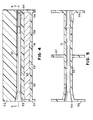
- FIG. 4 is a further enlarged sectional view of the coupler and counterweight of the rolling pin of FIG. 3;
- FIG. 5 is a sectional view taken generally along the line 5-5 in FIG. 4;
- FIG. 6 is a view similar to FIG. 5, with the shaft assembly rods installed;
- FIG. 7 is a view taken generally along the line 7-7 in FIG. 6 and rotated 90° counterclockwise;.
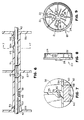
- FIG. 8 is a front elevational view of one of the end caps of the rolling pin of FIG. 3; and
- FIG. 9 is a rear or inner end elevational of the end cap of FIG. 8.
-
- Referring to FIGS. 1-3, there is illustrated a rolling device, viz., a
rolling pin 10 having a hollow roller 11 with a circularlycylindrical wall 12 defining aninner space 13 and having opposite ends terminating, respectively, atend edges - The opposite ends of the roller 11 are closed by
end caps 20, which are substantially identical in construction, wherefore only one will be described in detail. Referring also to FIGS. 8 and 9, eachend cap 20 has acircular end wall 21 provided adjacent to its outer edge with a axially extendingcylindrical wall 22 having an annularly recessedouter surface 23 provided with circumferentially spaced, radially outwardly projectingribs 24. Theend cap 20 is provided centrally of theend wall 21 with a generallycylindrical bushing 25, which projects in the direction of thecylindrical wall 22 substantially to the end of thecylindrical wall 22, and projects a slight distance in the other direction to define aangular boss 26. Thebushing 25 has a cylindrical bore therethrough defining abearing surface 27, with a rectangular notch 27a therein and extending radially outwardly. Formed through theend wall 21 at equiangularly spaced-apart locations around the bushing 25 are fourcircular drain holes 28. Formed on the inner surface of theend wall 21 and projecting a slight distance axially therefrom is a plurality of reenforcingribs 29, some of which extend radially inwardly from thecylindrical wall 22, and some of which extend the radially outwardly from the bushing 25. Theend caps 20 may be formed of a suitable plastic material, such as a suitable nylon, and are designed to be fitted in the ends of the roller 11, with theend wall 21 extending inside the roller 11, theribs 24 being dimensioned to provide a snug press fit, until theend edges end wall 21 and thecylindrical wall 22. - The rolling
pin 10 includes twohandles handle 30A will be described in detail. Thehandle 30A has a solidelongated body 31, which may be formed of a suitable plastic material, and is provided at one end with a flat, substantiallycircular end surface 32, and has a rounded, convexupper surface 33 and a substantially flattenedlower surface 34, thebody 31 terminating at a tapered, roundeddistal end 35. Formed through thebody 31 adjacent to thedistal end 35 is a counterbored hole or opening 36, which may be generally oval in transverse cross section, to facilitate hanging the rollingpin 10 on a hook or the like. Thehandle 30 is identical, except that it does not include thehole 36. - Referring also to FIGS. 6 and 7, the
rolling pin 10 also includes a shaft assembly, generally designated by thenumeral 40. Theshaft assembly 40 includes shaft structure comprising two shaft ends or rods 41 and 41A, which are of substantially identical construction. Each rod 41, 41A is formed of a suitable metal and has a main, straightelongated body 42 terminating at aninner end 43 and at outer end portion 44. The outer end portion 44 includes a bend or inclined portion 45 (FIG. 3), which is in turn integral with anoffset portion 46 parallel to themain body 42. Themain bodies 42 of the rods 41, 41A are, respectively, provided with radially outwardly projectingtabs inner ends 43, and respectively on opposite sides of the rods. The outer end portions 44 of the rods 41 and 41A are respectively fixed inside thehandles handles main body 42 of each rod projects outwardly from the center of thecircular end surface 32 of the handle, while theoffset portion 46 extends generally axially along the main portion of the handle, whereby thehandles main bodies 42 of the rods 41 and 41A. - Referring to FIGS. 3-7, the
shaft assembly 40 also includes acoupler 50, which may be formed of a suitable plastic material, and has an elongated, circularlycylindrical body 51 having a axialcylindrical bore 52 therethrough provided with an outwardly tapered or flaredsurface 53 adjacent to one end thereof. Thecoupler 50 has a wall 54 (FIG. 7) which is integral with thebody 51, being substantially tangent thereto along the entire length thereof and extending laterally equidistantly from both sides thereof. The coupler also includes aradial wall 55 which extends the length of thecylindrical body 51 and projects radially from the side thereof opposite thetangent wall 54 and substantially perpendicular to thetangent wall 54. Thecoupler 50 also hascircular end walls 56 integral therewith at the opposite ends thereof and a part-circularcentral wall 57 intermediate the ends thereof, thewalls body 51 substantially perpendicular to the axis thereof. Also extending between theend walls 56, spaced a predetermined distance radially outwardly of thetangent wall 54 and substantially parallel thereto, is a generallyrectangular support wall 58, which may have an elongated, axially extending, upstanding rib 59 (FIG. 4) centrally thereof. - An
elongated counterweight 60, which may be formed of a suitable metal, is disposed between thewalls counterweight 60 may have anelongated groove 61 therein to receive therib 59. Thecounterweight 60 may haveflanges 62 depending respectively from the opposite sides thereof intermediate the ends thereof for straddling the support wall 58 (FIGS. 3 and 7). Thecounterweight 60 may have a length so as to substantially occupy the space between theend walls 56 and a thickness so as to occupy the space between thewalls - Respectively formed in the opposite ends of the
bore 52 aretapered grooves cylindrical body 51 at diametrically opposite sides thereof arerectangular slots axial bore 52 adjacent to the inner ends of thetapered grooves - As described above, the
handles 30 may be prefabricated on the rods 41, 41A, as by insert molding. In assembly of therolling pin 10, theinner ends 43 of the rods are respectively inserted through thebushings 25 of theend caps 20, from the outer surface to the inner surface, thetabs counterweight 60 may be preassembled on thecoupler 50. In this regard, thecoupler 50, and particularly thesupport wall 58 thereof, has sufficient flexibility to permit insertion of thecounterweight 60 between thewalls coupler 50 to the installed position illustrated in FIGS. 3, 4 and 7. Next, theinner end 43 of the rod 41A is inserted in the non-flared end of theaxial bore 52 of the coupler, 40 with thetab 48A being received in the taperedgroove 64 for ensuring proper rotational orientation of the rod relative to thecoupler 50. Insertion continues until thetab 48A snap fits in theslot 66. In this regard, the radially outer edges of thetabs coupler 50, permits thetab 48A to be cammed past the inner end of thegroove 64 and into theslot 66. - Next, the coupler is inserted in the roller 11 and the
end cap 20 already assembled thereto is press-fitted in place in the adjacent end of the roller 11. Then, theinner end 43 of the other rod 41 is inserted into the opposite end of the roller 11 and into the adjacent end of the coupler bore 52, this insertion being facilitated by the flaredend surface 53 of the bore. As insertion is started, the rod 41 is rotated until thetab 48 fits into the taperedgroove 63 and then insertion continues until thetab 48 snap fits into theslot 65. The parts are dimensioned so that theend cap 20 will have to be press-fitted in place before insertion of the rod 41 is completed. The tapered nature of theend surface 53 and thegroove 63 permits guided insertion of the rod end even after theend cap 20 has been installed in place. - As thus assembled, the parts will be in the configuration illustrated in FIG. 3, with the rods 41, 41A being respectively freely rotatable within the
bushings 25, and with themain bodies 42 of the rods 41, 41A being coaxially aligned along a rotational axis of the roller 11. Thecoupler 50 will be biased by gravity to the illustrated at-rest position with thecounterweight 60 disposed downwardly. This will correspondingly cause thehandles 30 to be held in the raised position illustrated in FIG. 3 with the flattened surfaces 34 thereof facing downwardly. Thus, most of the volume of thehandles 30 will be disposed above the rotational axis of the roller 11, providing additional clearance beneath thehandles 30 for the user's fingers. When it is desired to apply additional force on the handles with the palms of the user's hands, thehandles 30 can simply be rotated so that the flattened surfaces 34 thereof face upwardly. - There results a rolling pin of a simple and economical construction which can be assembled without the use of fasteners, and which provides handles with flattened surfaces which, at rest, will always face downwardly.
- The matter set forth in the foregoing description and accompanying drawings is offered by way of illustration only and not as a limitation. While particular embodiments have been shown and described, it will be obvious to those skilled in the art that changes and modifications may be made without departing from the broader aspects of applicants' contribution. The actual scope of the protection sought is intended to be defined in the following claims when viewed in their proper perspective based on the prior art.
Claims (20)
- A rolling device comprising:an elongated roller having a longitudinal axis,two handles and,an elongated shaft assembly extending longitudinally through the roller for rotation relative thereto,the shaft assembly including two parts coupled together independently of the roller and respectively connected to the handles.
- The rolling device of claim 1, wherein the shaft assembly includes two end parts respectively connected to the handles and a coupler joining the end parts.
- The rolling device of claim 2, wherein the coupler has axial recesses therein, the end parts being respectively received in the recesses.
- The rolling device of claim 2, wherein the roller is hollow.
- The rolling device of claim 4, and further comprising two end caps respectively closing the ends of the roller and having axial bores therethrough respectively rotatably receiving the end parts of the shaft assembly.
- The rolling device of claim 1, wherein the roller is formed of metal.
- The rolling device of claim 1, wherein the roller is circularly cylindrical in shape.
- A rolling device comprising:an elongated roller having a longitudinal axis,two handles respectively coupled to the roller at opposite ends thereof for rotation relative thereto about the axis,each of the handles being coupled to the roller eccentrically with respect to the axis so as to be rotatable between a first position wherein most of the handle is disposed above the axis and a second position wherein most of the handle is disposed below the axis, anda counterweight coupled to the handles for biasing the handles to the first position.
- The rolling device of claim 8, and further comprising a shaft structure extending axially through the roller and having opposite end portions respectively connected to the handles externally of the roller.
- The rolling device of claim 9, wherein each of the end portions of the shaft structure has a portion offset from the axis and connected to the associated handle.
- The rolling device of claim 9, wherein the shaft structure includes two parts coupled together internally of the roller and independently thereof.
- The rolling device of claim 11, wherein the roller defines a hollow cylinder.
- The rolling device of claim 8, wherein each of the handles has a first rounded surface on one side of the handle and a second generally flattened surface on an opposite side of the handle.
- The rolling device of claim 13, wherein each handle is shaped and dimensioned so that, in use, when the handles are in the first position, the flattened surfaces face downwardly and are spaced from the associated work being rolled a distance sufficient to accommodate the fingers of a user's hand grasping the handle.
- A rolling device comprising:an elongated roller having a longitudinal axis,two handles and,an elongated shaft assembly extending longitudinally through the roller for rotation relative thereto,the shaft assembly including two end parts coupled together independently of the roller and respectively connected to the handles,each of the handles being coupled to the shaft assembly eccentrically with respect to the axis so as to be rotatable between a first position wherein most of the handle is disposed above the axis and a second position wherein most of the handle is disposed below the axisthe shaft assembly including a counterweight for biasing the handles to the first position.
- The rolling device of claim 15, wherein the shaft assembly includes a coupling part joining the two end parts.
- The rolling device of claim 16, wherein the counterweight is disposed on the coupling part.
- The rolling device of claim 15, wherein each of the end parts of the shaft structure has a portion offset from the axis and connected to the associated handle.
- The rolling device of claim 18, wherein each of the handles has a first rounded surface on one side of the handle and a second generally flattened surface on an opposite side of the handle.
- The rolling device of claim 15, wherein the roller is in the form of a hollow cylinder.
Applications Claiming Priority (2)
| Application Number | Priority Date | Filing Date | Title |
|---|---|---|---|
| US760435 | 1996-12-04 | ||
| US09/760,435 US6585629B2 (en) | 2001-01-12 | 2001-01-12 | Rolling pin with counterweighted eccentric handles |
Publications (2)
| Publication Number | Publication Date |
|---|---|
| EP1224866A1 true EP1224866A1 (en) | 2002-07-24 |
| EP1224866B1 EP1224866B1 (en) | 2006-09-20 |
Family
ID=25059104
Family Applications (1)
| Application Number | Title | Priority Date | Filing Date |
|---|---|---|---|
| EP01116448A Expired - Lifetime EP1224866B1 (en) | 2001-01-12 | 2001-07-06 | Rolling pin with counterweighted eccentric handles |
Country Status (5)
| Country | Link |
|---|---|
| US (1) | US6585629B2 (en) |
| EP (1) | EP1224866B1 (en) |
| AT (1) | ATE339890T1 (en) |
| CA (1) | CA2352401C (en) |
| DE (1) | DE60123205T2 (en) |
Cited By (1)
| Publication number | Priority date | Publication date | Assignee | Title |
|---|---|---|---|---|
| CN110973181A (en) * | 2019-12-29 | 2020-04-10 | 裴学华 | Rolling shaft |
Families Citing this family (8)
| Publication number | Priority date | Publication date | Assignee | Title |
|---|---|---|---|---|
| US7052450B2 (en) | 2004-02-05 | 2006-05-30 | Fiesta Products Llc | Silicone rolling pin |
| US20050176564A1 (en) * | 2004-02-06 | 2005-08-11 | Christy Michael J. | Solid metallic rolling pin |
| US7722516B2 (en) | 2006-02-10 | 2010-05-25 | Christopher Orlady | Cold rolling pin system |
| US20070261208A1 (en) * | 2006-05-15 | 2007-11-15 | Ishai Alon B | Cushioned handle |
| US20090018003A1 (en) * | 2007-07-11 | 2009-01-15 | Lynn Vendl | Rolling pin |
| US12082589B1 (en) | 2017-11-14 | 2024-09-10 | Defrancisci Machine Company Llc | Pasta rolling machine with thickness control |
| USD909834S1 (en) * | 2019-08-18 | 2021-02-09 | Helen Of Troy Limited | Rolling pin |
| DE102023210545A1 (en) * | 2023-10-25 | 2025-04-30 | Wmf Gmbh | Rolling pin, method for producing a rolling pin and use of the rolling pin |
Citations (4)
| Publication number | Priority date | Publication date | Assignee | Title |
|---|---|---|---|---|
| US2633815A (en) * | 1948-06-15 | 1953-04-07 | Ekco Products Company | Dough rolling device |
| US3565014A (en) * | 1968-10-03 | 1971-02-23 | Fausto Celorio Mendoza | Automatic tortilla-making machines |
| CH672972A5 (en) * | 1985-12-10 | 1990-01-31 | Funke Geb | Rolling pin - for infinitely variable dough thickness adjustable by turning handles |
| DE29621216U1 (en) * | 1996-12-06 | 1997-02-27 | Milde, Heinz, 81539 München | Dough roller |
Family Cites Families (25)
| Publication number | Priority date | Publication date | Assignee | Title |
|---|---|---|---|---|
| US353177A (en) | 1886-11-23 | Rolling-pin | ||
| US220669A (en) | 1879-10-14 | Improvement in rolling-pins | ||
| US78135A (en) | 1868-05-19 | Albert j | ||
| US154582A (en) | 1874-09-01 | Improvement in rolling-pins | ||
| US47979A (en) | 1865-05-30 | Improved rolling-pin | ||
| US50528A (en) | 1865-10-17 | Rolling-pin | ||
| US643780A (en) * | 1899-06-21 | 1900-02-20 | Clarence Lester Pitcher | Rolling-pin. |
| US1158111A (en) * | 1914-10-07 | 1915-10-26 | Edward C Ahlheim | Rolling-pin. |
| US1810050A (en) * | 1930-08-20 | 1931-06-16 | Klempp Gustave | Rolling pin |
| US2208729A (en) | 1939-11-13 | 1940-07-23 | John W Offutt | Rolling pin |
| US2683428A (en) * | 1952-04-03 | 1954-07-13 | Earl S Neal | Rolling pin |
| US2721524A (en) | 1954-11-17 | 1955-10-25 | Walter C Osborn | Rolling pin |
| US3001682A (en) * | 1959-10-21 | 1961-09-26 | United States Steel Corp | Self-centering rolls |
| US3322076A (en) | 1965-02-03 | 1967-05-30 | Richard B Cronheim | Rolling pins |
| GB1238776A (en) * | 1968-04-13 | 1971-07-07 | ||
| US3653338A (en) | 1970-09-17 | 1972-04-04 | Flambeau Plastics Corp | Hollow polyethylene rolling pin |
| US3831238A (en) | 1973-03-26 | 1974-08-27 | J Adams | Rolling pin |
| US3847144A (en) * | 1973-06-27 | 1974-11-12 | R Wright | Reducing roller device |
| US3935750A (en) * | 1973-10-23 | 1976-02-03 | Maroth Arthur M | Counterbalanced mechanical speed-change mechanism |
| US4070742A (en) | 1976-12-13 | 1978-01-31 | Claire Dorfman | Motorized rolling pin |
| US4107830A (en) | 1977-05-02 | 1978-08-22 | Thomson George V | Rolling pin construction |
| US4426200A (en) | 1982-09-27 | 1984-01-17 | Sylvio Muller | Rolling pin apparatus |
| US5081885A (en) * | 1989-12-28 | 1992-01-21 | Consulier Industries, Inc. | Drive with oscillator-coupled transversely moving gear elements |
| US5577995A (en) * | 1991-06-13 | 1996-11-26 | Grace L. Walker | Spinal and soft tissue mobilizer |
| US5217369A (en) * | 1992-05-28 | 1993-06-08 | Micron Techology, Inc. | Atmospheric furnace door counterbalance |
-
2001
- 2001-01-12 US US09/760,435 patent/US6585629B2/en not_active Expired - Lifetime
- 2001-07-04 CA CA002352401A patent/CA2352401C/en not_active Expired - Fee Related
- 2001-07-06 EP EP01116448A patent/EP1224866B1/en not_active Expired - Lifetime
- 2001-07-06 AT AT01116448T patent/ATE339890T1/en not_active IP Right Cessation
- 2001-07-06 DE DE60123205T patent/DE60123205T2/en not_active Expired - Fee Related
Patent Citations (4)
| Publication number | Priority date | Publication date | Assignee | Title |
|---|---|---|---|---|
| US2633815A (en) * | 1948-06-15 | 1953-04-07 | Ekco Products Company | Dough rolling device |
| US3565014A (en) * | 1968-10-03 | 1971-02-23 | Fausto Celorio Mendoza | Automatic tortilla-making machines |
| CH672972A5 (en) * | 1985-12-10 | 1990-01-31 | Funke Geb | Rolling pin - for infinitely variable dough thickness adjustable by turning handles |
| DE29621216U1 (en) * | 1996-12-06 | 1997-02-27 | Milde, Heinz, 81539 München | Dough roller |
Cited By (2)
| Publication number | Priority date | Publication date | Assignee | Title |
|---|---|---|---|---|
| CN110973181A (en) * | 2019-12-29 | 2020-04-10 | 裴学华 | Rolling shaft |
| CN110973181B (en) * | 2019-12-29 | 2021-07-20 | 义乌市择木工业产品设计有限公司 | Rolling shaft |
Also Published As
| Publication number | Publication date |
|---|---|
| ATE339890T1 (en) | 2006-10-15 |
| US20020094921A1 (en) | 2002-07-18 |
| EP1224866B1 (en) | 2006-09-20 |
| US6585629B2 (en) | 2003-07-01 |
| DE60123205T2 (en) | 2006-12-28 |
| DE60123205D1 (en) | 2006-11-02 |
| CA2352401C (en) | 2007-05-22 |
| CA2352401A1 (en) | 2002-07-12 |
Similar Documents
| Publication | Publication Date | Title |
|---|---|---|
| EP1224866B1 (en) | Rolling pin with counterweighted eccentric handles | |
| US8533912B2 (en) | Grab handle mounting assembly | |
| US9475183B2 (en) | Non-rotatable telescopic handle construction | |
| US7491156B1 (en) | Fixed weight dumbbell and barbell system | |
| JP2001512054A (en) | Hand tools | |
| US20170112092A1 (en) | Animal food dispenser | |
| US7216569B2 (en) | Screwdriver handle | |
| WO2002070210A9 (en) | Dough roller | |
| US10603779B2 (en) | Adaptable pole for a pool device | |
| US4272972A (en) | Universal joint | |
| AU2003271287A1 (en) | Paint roller support | |
| US4928792A (en) | Joint for ladders | |
| SE528799C2 (en) | Screwdriver tools | |
| WO2008088544A2 (en) | Crimping pliers and method for simultaneously severing a tube and closing the tube ends by he help of a malleable sleeve | |
| US8911337B2 (en) | Roller cover support assembly with roller cover retention spring | |
| US3954205A (en) | Toothpaste dispenser | |
| US20230211372A1 (en) | Cage for a paint roller | |
| US20020119825A1 (en) | Side-bar baton system | |
| USD762757S1 (en) | Shear pin | |
| EP1781869A1 (en) | A stair rail apparatus | |
| US20210402274A1 (en) | Baton having tubular bodies | |
| JP3013577U (en) | Hinges for hinges | |
| EP1714752B1 (en) | Scissors | |
| AU719889B3 (en) | A toy building element | |
| KR102305277B1 (en) | Handrail connection structure for the disabled |
Legal Events
| Date | Code | Title | Description |
|---|---|---|---|
| PUAI | Public reference made under article 153(3) epc to a published international application that has entered the european phase |
Free format text: ORIGINAL CODE: 0009012 |
|
| AK | Designated contracting states |
Kind code of ref document: A1 Designated state(s): AT BE CH CY DE DK ES FI FR GB GR IE IT LI LU MC NL PT SE TR |
|
| AX | Request for extension of the european patent |
Free format text: AL;LT;LV;MK;RO;SI |
|
| 17P | Request for examination filed |
Effective date: 20030110 |
|
| AKX | Designation fees paid |
Designated state(s): AT BE CH CY DE DK ES FI FR GB GR IE IT LI LU MC NL PT SE TR |
|
| 17Q | First examination report despatched |
Effective date: 20040903 |
|
| RAP1 | Party data changed (applicant data changed or rights of an application transferred) |
Owner name: HELEN OF TROY LIMITED |
|
| GRAP | Despatch of communication of intention to grant a patent |
Free format text: ORIGINAL CODE: EPIDOSNIGR1 |
|
| GRAS | Grant fee paid |
Free format text: ORIGINAL CODE: EPIDOSNIGR3 |
|
| GRAA | (expected) grant |
Free format text: ORIGINAL CODE: 0009210 |
|
| AK | Designated contracting states |
Kind code of ref document: B1 Designated state(s): AT BE CH CY DE DK ES FI FR GB GR IE IT LI LU MC NL PT SE TR |
|
| PG25 | Lapsed in a contracting state [announced via postgrant information from national office to epo] |
Ref country code: IT Free format text: LAPSE BECAUSE OF FAILURE TO SUBMIT A TRANSLATION OF THE DESCRIPTION OR TO PAY THE FEE WITHIN THE PRESCRIBED TIME-LIMIT;WARNING: LAPSES OF ITALIAN PATENTS WITH EFFECTIVE DATE BEFORE 2007 MAY HAVE OCCURRED AT ANY TIME BEFORE 2007. THE CORRECT EFFECTIVE DATE MAY BE DIFFERENT FROM THE ONE RECORDED. Effective date: 20060920 Ref country code: CH Free format text: LAPSE BECAUSE OF FAILURE TO SUBMIT A TRANSLATION OF THE DESCRIPTION OR TO PAY THE FEE WITHIN THE PRESCRIBED TIME-LIMIT Effective date: 20060920 Ref country code: AT Free format text: LAPSE BECAUSE OF FAILURE TO SUBMIT A TRANSLATION OF THE DESCRIPTION OR TO PAY THE FEE WITHIN THE PRESCRIBED TIME-LIMIT Effective date: 20060920 Ref country code: LI Free format text: LAPSE BECAUSE OF FAILURE TO SUBMIT A TRANSLATION OF THE DESCRIPTION OR TO PAY THE FEE WITHIN THE PRESCRIBED TIME-LIMIT Effective date: 20060920 Ref country code: FI Free format text: LAPSE BECAUSE OF FAILURE TO SUBMIT A TRANSLATION OF THE DESCRIPTION OR TO PAY THE FEE WITHIN THE PRESCRIBED TIME-LIMIT Effective date: 20060920 Ref country code: NL Free format text: LAPSE BECAUSE OF FAILURE TO SUBMIT A TRANSLATION OF THE DESCRIPTION OR TO PAY THE FEE WITHIN THE PRESCRIBED TIME-LIMIT Effective date: 20060920 Ref country code: BE Free format text: LAPSE BECAUSE OF FAILURE TO SUBMIT A TRANSLATION OF THE DESCRIPTION OR TO PAY THE FEE WITHIN THE PRESCRIBED TIME-LIMIT Effective date: 20060920 |
|
| REG | Reference to a national code |
Ref country code: GB Ref legal event code: FG4D |
|
| REG | Reference to a national code |
Ref country code: CH Ref legal event code: EP |
|
| REG | Reference to a national code |
Ref country code: IE Ref legal event code: FG4D |
|
| REF | Corresponds to: |
Ref document number: 60123205 Country of ref document: DE Date of ref document: 20061102 Kind code of ref document: P |
|
| PG25 | Lapsed in a contracting state [announced via postgrant information from national office to epo] |
Ref country code: SE Free format text: LAPSE BECAUSE OF FAILURE TO SUBMIT A TRANSLATION OF THE DESCRIPTION OR TO PAY THE FEE WITHIN THE PRESCRIBED TIME-LIMIT Effective date: 20061220 Ref country code: DK Free format text: LAPSE BECAUSE OF FAILURE TO SUBMIT A TRANSLATION OF THE DESCRIPTION OR TO PAY THE FEE WITHIN THE PRESCRIBED TIME-LIMIT Effective date: 20061220 |
|
| PG25 | Lapsed in a contracting state [announced via postgrant information from national office to epo] |
Ref country code: ES Free format text: LAPSE BECAUSE OF FAILURE TO SUBMIT A TRANSLATION OF THE DESCRIPTION OR TO PAY THE FEE WITHIN THE PRESCRIBED TIME-LIMIT Effective date: 20061231 |
|
| NLV1 | Nl: lapsed or annulled due to failure to fulfill the requirements of art. 29p and 29m of the patents act | ||
| PG25 | Lapsed in a contracting state [announced via postgrant information from national office to epo] |
Ref country code: PT Free format text: LAPSE BECAUSE OF FAILURE TO SUBMIT A TRANSLATION OF THE DESCRIPTION OR TO PAY THE FEE WITHIN THE PRESCRIBED TIME-LIMIT Effective date: 20070312 |
|
| REG | Reference to a national code |
Ref country code: CH Ref legal event code: PL |
|
| ET | Fr: translation filed | ||
| PLBE | No opposition filed within time limit |
Free format text: ORIGINAL CODE: 0009261 |
|
| STAA | Information on the status of an ep patent application or granted ep patent |
Free format text: STATUS: NO OPPOSITION FILED WITHIN TIME LIMIT |
|
| 26N | No opposition filed |
Effective date: 20070621 |
|
| GBPC | Gb: european patent ceased through non-payment of renewal fee |
Effective date: 20070706 |
|
| PG25 | Lapsed in a contracting state [announced via postgrant information from national office to epo] |
Ref country code: DE Free format text: LAPSE BECAUSE OF NON-PAYMENT OF DUE FEES Effective date: 20080201 Ref country code: MC Free format text: LAPSE BECAUSE OF NON-PAYMENT OF DUE FEES Effective date: 20070731 Ref country code: GR Free format text: LAPSE BECAUSE OF FAILURE TO SUBMIT A TRANSLATION OF THE DESCRIPTION OR TO PAY THE FEE WITHIN THE PRESCRIBED TIME-LIMIT Effective date: 20061221 |
|
| PG25 | Lapsed in a contracting state [announced via postgrant information from national office to epo] |
Ref country code: GB Free format text: LAPSE BECAUSE OF NON-PAYMENT OF DUE FEES Effective date: 20070706 |
|
| REG | Reference to a national code |
Ref country code: FR Ref legal event code: ST Effective date: 20080331 |
|
| PG25 | Lapsed in a contracting state [announced via postgrant information from national office to epo] |
Ref country code: FR Free format text: LAPSE BECAUSE OF NON-PAYMENT OF DUE FEES Effective date: 20070731 |
|
| PG25 | Lapsed in a contracting state [announced via postgrant information from national office to epo] |
Ref country code: IE Free format text: LAPSE BECAUSE OF NON-PAYMENT OF DUE FEES Effective date: 20070706 |
|
| PG25 | Lapsed in a contracting state [announced via postgrant information from national office to epo] |
Ref country code: CY Free format text: LAPSE BECAUSE OF FAILURE TO SUBMIT A TRANSLATION OF THE DESCRIPTION OR TO PAY THE FEE WITHIN THE PRESCRIBED TIME-LIMIT Effective date: 20060920 Ref country code: LU Free format text: LAPSE BECAUSE OF NON-PAYMENT OF DUE FEES Effective date: 20070706 |
|
| PG25 | Lapsed in a contracting state [announced via postgrant information from national office to epo] |
Ref country code: TR Free format text: LAPSE BECAUSE OF FAILURE TO SUBMIT A TRANSLATION OF THE DESCRIPTION OR TO PAY THE FEE WITHIN THE PRESCRIBED TIME-LIMIT Effective date: 20060920 |