EP1224853A1 - Braking and clutching device for bush cutting apparatus - Google Patents
Braking and clutching device for bush cutting apparatus Download PDFInfo
- Publication number
- EP1224853A1 EP1224853A1 EP02000707A EP02000707A EP1224853A1 EP 1224853 A1 EP1224853 A1 EP 1224853A1 EP 02000707 A EP02000707 A EP 02000707A EP 02000707 A EP02000707 A EP 02000707A EP 1224853 A1 EP1224853 A1 EP 1224853A1
- Authority
- EP
- European Patent Office
- Prior art keywords
- clutch
- brake
- cutter
- rotating member
- drive source
- Prior art date
- Legal status (The legal status is an assumption and is not a legal conclusion. Google has not performed a legal analysis and makes no representation as to the accuracy of the status listed.)
- Granted
Links
Images


Classifications
-
- A—HUMAN NECESSITIES
- A01—AGRICULTURE; FORESTRY; ANIMAL HUSBANDRY; HUNTING; TRAPPING; FISHING
- A01D—HARVESTING; MOWING
- A01D34/00—Mowers; Mowing apparatus of harvesters
- A01D34/01—Mowers; Mowing apparatus of harvesters characterised by features relating to the type of cutting apparatus
- A01D34/412—Mowers; Mowing apparatus of harvesters characterised by features relating to the type of cutting apparatus having rotating cutters
- A01D34/63—Mowers; Mowing apparatus of harvesters characterised by features relating to the type of cutting apparatus having rotating cutters having cutters rotating about a vertical axis
- A01D34/67—Mowers; Mowing apparatus of harvesters characterised by features relating to the type of cutting apparatus having rotating cutters having cutters rotating about a vertical axis hand-guided by a walking operator
- A01D34/68—Mowers; Mowing apparatus of harvesters characterised by features relating to the type of cutting apparatus having rotating cutters having cutters rotating about a vertical axis hand-guided by a walking operator with motor driven cutters or wheels
-
- A—HUMAN NECESSITIES
- A01—AGRICULTURE; FORESTRY; ANIMAL HUSBANDRY; HUNTING; TRAPPING; FISHING
- A01D—HARVESTING; MOWING
- A01D34/00—Mowers; Mowing apparatus of harvesters
- A01D34/835—Mowers; Mowing apparatus of harvesters specially adapted for particular purposes
- A01D34/90—Mowers; Mowing apparatus of harvesters specially adapted for particular purposes for carrying by the operator
-
- A—HUMAN NECESSITIES
- A01—AGRICULTURE; FORESTRY; ANIMAL HUSBANDRY; HUNTING; TRAPPING; FISHING
- A01D—HARVESTING; MOWING
- A01D34/00—Mowers; Mowing apparatus of harvesters
- A01D34/01—Mowers; Mowing apparatus of harvesters characterised by features relating to the type of cutting apparatus
- A01D34/412—Mowers; Mowing apparatus of harvesters characterised by features relating to the type of cutting apparatus having rotating cutters
- A01D34/63—Mowers; Mowing apparatus of harvesters characterised by features relating to the type of cutting apparatus having rotating cutters having cutters rotating about a vertical axis
- A01D34/67—Mowers; Mowing apparatus of harvesters characterised by features relating to the type of cutting apparatus having rotating cutters having cutters rotating about a vertical axis hand-guided by a walking operator
- A01D34/68—Mowers; Mowing apparatus of harvesters characterised by features relating to the type of cutting apparatus having rotating cutters having cutters rotating about a vertical axis hand-guided by a walking operator with motor driven cutters or wheels
- A01D34/6806—Driving mechanisms
- A01D34/6812—Braking or clutching mechanisms
-
- F—MECHANICAL ENGINEERING; LIGHTING; HEATING; WEAPONS; BLASTING
- F16—ENGINEERING ELEMENTS AND UNITS; GENERAL MEASURES FOR PRODUCING AND MAINTAINING EFFECTIVE FUNCTIONING OF MACHINES OR INSTALLATIONS; THERMAL INSULATION IN GENERAL
- F16D—COUPLINGS FOR TRANSMITTING ROTATION; CLUTCHES; BRAKES
- F16D59/00—Self-acting brakes, e.g. coming into operation at a predetermined speed
- F16D59/02—Self-acting brakes, e.g. coming into operation at a predetermined speed spring-loaded and adapted to be released by mechanical, fluid, or electromagnetic means
-
- A—HUMAN NECESSITIES
- A01—AGRICULTURE; FORESTRY; ANIMAL HUSBANDRY; HUNTING; TRAPPING; FISHING
- A01D—HARVESTING; MOWING
- A01D2101/00—Lawn-mowers
-
- F—MECHANICAL ENGINEERING; LIGHTING; HEATING; WEAPONS; BLASTING
- F16—ENGINEERING ELEMENTS AND UNITS; GENERAL MEASURES FOR PRODUCING AND MAINTAINING EFFECTIVE FUNCTIONING OF MACHINES OR INSTALLATIONS; THERMAL INSULATION IN GENERAL
- F16D—COUPLINGS FOR TRANSMITTING ROTATION; CLUTCHES; BRAKES
- F16D2121/00—Type of actuator operation force
- F16D2121/14—Mechanical
- F16D2121/16—Mechanical for releasing a normally applied brake
-
- F—MECHANICAL ENGINEERING; LIGHTING; HEATING; WEAPONS; BLASTING
- F16—ENGINEERING ELEMENTS AND UNITS; GENERAL MEASURES FOR PRODUCING AND MAINTAINING EFFECTIVE FUNCTIONING OF MACHINES OR INSTALLATIONS; THERMAL INSULATION IN GENERAL
- F16D—COUPLINGS FOR TRANSMITTING ROTATION; CLUTCHES; BRAKES
- F16D2123/00—Multiple operation forces
-
- F—MECHANICAL ENGINEERING; LIGHTING; HEATING; WEAPONS; BLASTING
- F16—ENGINEERING ELEMENTS AND UNITS; GENERAL MEASURES FOR PRODUCING AND MAINTAINING EFFECTIVE FUNCTIONING OF MACHINES OR INSTALLATIONS; THERMAL INSULATION IN GENERAL
- F16D—COUPLINGS FOR TRANSMITTING ROTATION; CLUTCHES; BRAKES
- F16D2129/00—Type of operation source for auxiliary mechanisms
- F16D2129/04—Mechanical
- F16D2129/043—Weights
Definitions
- This invention relates generally to a bush cutting apparatus, and more particularly to an improved brake mechanism for stopping rotation of a cutter blade of a bush cutting apparatus.
- Brake mechanisms of bush cutting apparatuses are known, for example, from Japanese Utility Model Laid-Open Publication Nos. 51-53248 and 51-99039.
- the first-mentioned 51-53248 publication discloses a bush cutting apparatus which includes brake shoes and cam plates for moving the brake shoes into and out of engagement with a driven shaft. As a human operator releases a brake bar, the cam plates are caused, via springs, to pivot to press the brake shoes against the driven shaft, so that there is automatically produced a braking force to stop rotation of the rotary cutter.
- the second-mentioned 51-99039 publication discloses a bush cutting apparatus which includes a brake lining provided along the outer periphery of a clutch drum. As a human operator releases a lever, the brake lining comes into engagement with the outer periphery of the clutch drum and a signal is generated from a movable contact to deactivate a prime mover or drive source, so that a rotary cutter can be caused to stop its rotation.
- a control rod coupled to one end of a connecting wire extends through a hole formed in a clutch housing, and measures for maximizing dust-tightness and water-tightness must be taken in relation to the hole in the clutch housing. Furthermore, extra operations are necessary for checking and adjusting the tension of the connecting wire coupled at the other end to the lever, which would require an extra time and labor.
- an object of the present invention to provide an improved bush cutting apparatus which can achieve an enhanced operability and enhanced dust-tightness and water-tightness and which can be manufactured at reduced costs.
- an improved bush cutting apparatus of the type which includes a cutter-blade driving shaft having a cutter blade attached thereto and a drive source having an output shaft operatively connected with the cutter-blade driving shaft for rotating the cutter-blade driving shaft via a clutch mechanism and a brake mechanism.
- the clutch mechanism in the bush cutting apparatus of the invention comprises: a rotating member mounted on the output shaft of the drive source; a clutch moving member mounted on the rotating member for sliding movement along a radial direction of the rotating member, the clutch moving member having a tapered outer side surface; a clutch drum mounted on the cutter-blade driving shaft for axial movement therealong and having a tapered portion with an inner surface corresponding in contour to the tapered outer side surface of the clutch moving member; and a clutch resilient member for normally pulling the clutch moving member toward an axial centerline of the rotating member.
- the brake mechanism comprises: a brake shoe formed at a tip of an open end portion of the clutch drum that constitutes a greatest diameter region of the tapered portion in the clutch drum; a brake pad secured to a non-rotating fixed housing in opposed relation to the brake shoe; and a braking resilient member for normally pressing the brake shoe against the brake pad.
- the clutch moving member is moved radially outward to press the clutch drum by centrifugal force in such a manner that the clutch drum is caused, by the tapered outer side surface of the clutch moving member, to slide to a non-braking position.
- the brake mechanism When the rotation of the rotating member and hence of the cutter blade has fallen below the predetermined rotation speed, the brake mechanism is automatically activated to terminate the rotation of the cutter blade. Namely, when the number of rotations of the drive source and hence of the clutch mechanism has fallen below a predetermined value, the moving member in the clutch mechanism is disengaged from the clutch drum, and thus the clutch drum is freed and resiliently slid, by the brake mechanism, back to a predetermined braking position where the brake shoe is pressed against the brake pad to apply the brakes; namely, in this case, the brake mechanism causes the brake shoe to be pressed against the brake pad via the braking resilient member. As a result, the clutch drum having the brake shoe as well as the cutter-blade driving shaft and the cutter blade is caused to stop rotating.
- the present invention can eliminate the need for a human operator to manually manipulate a brake lever or the like, and thus allows the human operator to manipulate the bush cutting apparatus with a significantly enhanced operability.
- the clutch moving member in the clutch mechanism is caused to slide radially outward along the rotating member in such a manner that the clutch moving member slides the clutch drum to the non-braking position against the bias of the braking resilient member while transmitting the rotational force from the rotating member to the clutch drum by means of the tapered outer side surface, so that the brake shoe formed on the clutch drum is disengaged from the brake pad to release the brakes.
- the present invention can dispense with a lever and wire for braking operation by the human operator and eliminate a need for an apparatus housing to have a hole for passing component parts, such as a wire and rod, through the housing.
- the present invention can achieve enhanced dust-tightness and water-tightness of the bush cutting apparatus.
- the parts, such as the brake lever and wire can be dispensed with, the bush cutting apparatus of the present invention can be manufactured at reduced costs.
- another improved bush cutting apparatus of the type including a cutter-blade driving shaft having a cutter blade attached thereto and a drive source having an output shaft operatively connected with the cutter-blade driving shaft for rotating the cutter-blade driving shaft via a clutch mechanism and brake mechanism.
- the clutch mechanism comprises: a rotating member mounted on the output shaft of the drive source; a clutch moving member mounted on the rotating member for movement along radial and axial directions of the rotating member; a clutch drum mounted on the cutter-blade driving shaft for axial movement therealong; and a clutch resilient member for normally pulling the clutch moving member toward an axial centerline of the rotating member.
- the brake mechanism comprises: a brake shoe formed at a tip of an open end portion of the clutch drum; a brake pad secured to a non-rotating fixed housing in opposed relation to the brake shoe; and a braking resilient member for normally pressing the brake shoe against the brake pad.
- the moving member in the clutch mechanism is disengaged from the clutch drum, and thus the clutch drum is freed and resiliently slid, by the brake mechanism, back to a predetermined braking position where the brake shoe is pressed against the brake pad to apply the brakes; namely, the brake mechanism causes the brake shoe to be pressed against the brake pad via the braking resilient member.
- the clutch drum having the brake shoe as well as the cutter-blade driving shaft and the cutter blade is caused to stop rotating.
- the present invention can eliminate the need for a human operator to manually manipulate a brake lever or the like, and thus allows the human operator to manipulate the bush cutting apparatus with a significantly enhanced operability.
- the clutch moving member in the clutch mechanism is caused not only to slide radially outward along the rotating member but also move in the axial direction away from the brake pad. Such movement of the clutch moving member causes the brake shoe of the clutch drum to disengage from the brake drum, thereby releasing the brakes.
- the present invention can dispense with a lever and wire for braking operation by the human operator and eliminate a need for an apparatus housing to have a hole for passing component parts, such as a wire and rod, through the housing.
- the present invention can achieve enhanced dust-tightness and water-tightness of the bush cutting apparatus.
- a plurality of the clutch moving members are provided symmetrically with each other about the axial centerline of the rotating member.
- the symmetrical arrangement can distribute the weights of the moving members and thus can reliably prevent unbalance during the rotation. Further, the symmetrical arrangement permits synchronization between the two moving members and thereby allows the clutch mechanism and brake mechanism to operate smoothly, so that reliable brake performance can be accomplished.
- Fig. 1 is a view showing a manner in which a human operator cuts bushes using a bush cutting apparatus in accordance with a first embodiment of the present invention.
- the human operator is shown here as carrying the bush cutting apparatus 10 with a belt 11 suspended from one of operator's shoulders and gripping a handling portion 12 of the cutting apparatus 10 with one of his or her hands.
- the bush cutting apparatus 10 includes a rotary cutting blade 13 and various other components as will be described in detail hereinbelow.
- Fig. 2 is a partly-sectional front view of a body section of the cutting apparatus 10 circled at 2 in Fig. 1.
- the bush cutting apparatus 10 includes a prime mover or drive source 21, a clutch mechanism 23 and brake mechanism 24 connected to a crankshaft 22 of the drive source 21, and a cutter-blade driving shaft 25 connected to the clutch mechanism 23.
- the clutch mechanism 23 includes a rotating member 41 mounted on the crankshaft 22 functioning as an output shaft of the drive source 21.
- the clutch mechanism 23 also includes two moving members 45 each having, on its outer side (i.e., the side remote from the crankshaft 22), a tapered surface 44 tapering in a direction away from the drive source 21, and the moving members 45 are mounted on the rotating member 41 for sliding movement along radial directions of the rotating member 41 as denoted by arrow 2 ⁇ .
- the clutch mechanism 23 further includes a clutch drum 31 that is mounted on the cutter-blade driving shaft 25 for movement along the axial direction (denoted by arrow 1 ⁇ ) of the shaft 25 and that has a tapered portion 43 with an inner surface corresponding in contour to the tapered outer side surfaces 44 of the moving members 45.
- the clutch mechanism 23 further includes resilient members 46 (Fig. 3) that normally pulls the moving members 45 toward each other, i.e. toward the centerline C of the rotating member 41.
- Brake mechanism 24 includes a brake shoe 33 formed at the tip of an open end portion 32, closer to the drive source 21, of the clutch drum 31 which constitutes a greatest-diameter portion of the tapered portion 43, brake pads 35 secured to a non-rotating fixed housing 34 in axially-opposed relation to the brake shoe 33, and a braking resilient member 36 for normally pressing the brake shoe 33 against the brake pads 35.
- the prime mover or drive source 21 includes a cylinder 51, a piston 52, the above-mentioned crankshaft 22, and a sparking plug 63.
- Reference numeral 54 in Fig. 2 represents a fuel tank, 55 an oil tank, and 56 a starting device.
- the tapered clutch drum 31 has the brake shoe 33 of the brake mechanism 24 formed, as a kind of radial flange, at the tip of the open end portion (right end portion in Fig. 2) 32 having the greatest diameter D, and a disk-shaped connecting portion 61 at its bottom end portion (left end portion in Fig. 2) having a smallest diameter.
- Connecting shaft 62 is coupled to the connecting portion 61 and has serrations 62a in its axial middle portion for coupling with the cutter-blade driving shaft 25.
- the cutter-blade driving shaft 25 has, in its end portion closer to the clutch drum 31, serrations 25a meshing with the serrations 62a by a given axial length L1.
- the housing 34 has a bearing portion 65 centrally on its body 64, and pad mounting portions 67 at its open end closer to the drive source 21.
- the brake pads 35 are each fixed to a corresponding one of the pad mounting portions 67 via a rug 68.
- Bearing unit 71 is fitted in the bearing portion 65, and a collar 72 is snugly fitted between the bearing unit 71 and the connecting shaft 62.
- the braking resilient member 36 abuts at its one end against the collar 72 and at the other end against the connecting portion 61 of the clutch drum 31.
- the collar 72 is made, for example, of white metal and constructed to function as sliding bearings. Further, the braking resilient member 36 comprises, for example, a dish-shaped spring.
- the rotating member 41 has a central mounting portion 73 projecting axially toward the drive source 21 and coupled to the crankshaft 22, and guide portions 74 projecting laterally from a base of the central mounting portion 73 in opposite directions for guiding respective ones of the moving members 45 of the clutch mechanism 23.
- Each of the clutch moving members 45 having the tapered outer side surface 44, has an inner protrusion 75 slidably fitted in the corresponding guide section 74.
- Each of the clutch moving members 45 also has an engaging portion 76 (Fig. 3) adjacent the inner protrusion 75 for engaging corresponding ends of the resilient members 46 (Fig. 3) of the clutch mechanism 23.
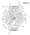
- Fig. 3 is a sectional view of the bush cutting apparatus taken along the 3 - 3 line of Fig. 2.
- the two clutch moving members 45 are positioned symmetrically with (diametrically opposed to) each other about the centerline C of the rotating member 41 and radially slidable along the guide portions 74 as denoted by arrow 2 ⁇ .
- the diametrically-opposed clutch moving members 45 are engaged by the resilient members 46 and the clutch drum 31 has the tapered portion 43 to be acted on or pressed by the clutch moving members 45.
- the brake shoe 33 of the brake mechanism 24 is formed integrally on the open end portion 32 of the clutch drum 31, and the brake pads 35 are secured to the housing 34 in opposed relation to the brake shoe 33.
- Reference numeral 77 in Fig. 3 represents a key interconnecting the rotating member 41 and the crankshaft 22.
- the brake shoe 33 is normally pressed against the brake pads 35 as denoted by arrow 3 ⁇ .
- the drive source 21 is first activated, and then the rotating speed, i.e. the number of rotations, of the drive source 21 is caused to increase progressively.
- the brake shoe 33 is moved away or disengaged from the brake pads 35 by a distance Y.
- the number of rotations can be further increased to allow the cutter-blade driving shaft 25 to rotate at a corresponding rate as denoted by arrow 5 ⁇ .
- the clutch drum 31 resiliently moves back to the original position by force F2 exerted by the braking resilient member 36, where the brake shoe 33 is again pressed against the brake pads 35 to thereby apply the brakes such that the rotation of the clutch drum 31 and hence the rotation of the cutter-blade driving shaft 25 is terminated instantaneously.
- the clutch moving members 45 are resiliently slid away from the clutch drum 31 by pulling force F1 of the resilient members 46, while the brake shoe 33 of the brake mechanism 24 is resiliently brought back into abutment against the brake pads 35 to automatically apply the brakes.
- Such arrangements can eliminate the need for the human operator to perform manual braking operation to stop the rotation of the cutter-blade driving shaft 25, and thereby can enhance the operability of the bush cutting apparatus 10.
- the brake mechanism 24 is composed of the brake shoe 33 formed on the clutch drum 31, brake pads 35 provided on the housing 34 and braking resilient member 36 for normally pressing the brake shoe 33 against the brake pads 35, there is no need for the housing 34 to have a hole for passing component parts, such as a wire and rod, through the housing 34, so that enhanced dust-tightness and water-tightness can be achieved.
- the brake mechanism 24 is arranged to automatically apply the brakes when the predetermined number of rotations is not reached, it is possible to dispense with component parts to be used for manual braking operation, such as a handling lever and wire, and thus the manufacturing costs of the bush cutting apparatus can be reduced considerably.
- the weights of the component parts can be distributed uniformly to the center axis of the rotation, which can reliably prevent unwanted unbalance during the rotation.
- the symmetrical arrangement permits synchronization between the two clutch moving members 45 and thereby allows the clutch mechanism 23 and brake mechanism 24 to operate smoothly, so that reliable brakes can be assured.
- the collar 72 is mounted on the connecting shaft 62 of the clutch drum 31 and also fitted in the bearing unit 71, the collar 72 can support the connecting shaft 62 with a reduced friction coefficient, so that the connecting shaft 62 and hence the brake shoe 33 can be readily slid to the non-braking position (in the arrow 4 ⁇ direction of Fig. 4B). Furthermore, because the serrations 25a of the cutter-blade driving shaft 25 mesh with the serrations 62a of the connecting shaft 62 by the axial length L1, the connecting shaft 62 allows the brake shoe 33 to slide to the non-braking position (in the arrow 4 ⁇ direction of Fig. 4B) while transmitting the rotational force.
- Fig. 5 is a sectional view of the bush cutting apparatus, in which the elements of the same structures and functions as those in Fig. 2 are represented by the same reference characters.
- Clutch mechanism 23B includes a rotating member 84 mounted on a crankshaft 22 functioning as an output shaft of a drive source 21, and clutch moving members 85 mounted on the rotating member 84 for movement both along the radially outward directions of the rotating member 84 as denoted by arrow 2 ⁇ and along the axial direction of the crankshaft 22 as denoted by arrow 1 ⁇ .
- the clutch mechanism 23 further includes a clutch drum 81 that is mounted on a cutter-blade driving shaft 25 for movement along the axial direction (arrow 1 ⁇ direction) of the driving shaft 25, and clutch resilient members 46 (Fig. 6) that normally pulls the moving members 85 toward each other, i.e. toward the centerline C of the rotating member 84.
- Brake mechanism 24B includes a brake shoe 83 formed, as a kind of radial flange, at the tip of its open end portion (right end portion in Fig. 5) 82 of the clutch drum 81, brake pads35 secured to a non-rotating fixed housing 34 in axially-opposed relation to the brake shoe 83, and a braking resilient member 36 for normally pressing the brake shoe 83 against the brake pads 35.
- the clutch drum 81 has the brake shoe 83 of the brake mechanism 24B formed at the tip of its cylindrical portion 86, and a disk-shaped connecting portion 61 at its bottom end portion (left end portion in Fig. 5). Connecting shaft 62 is coupled to the connecting portion 61 of the clutch drum 81.
- Each of the clutch moving members 45 has a tapered outer side surface 87, and it has an inner protrusion 88 having an orthogonal portion 88a and a slanted portion 88b.
- Each of the clutch moving members 85 also has an engaging portion 76 (see Fig. 3) adjacent the inner protrusion 88 for engaging corresponding ends of the resilient members 46 of the clutch mechanism 23B.
- the brake shoe 83 is normally pressed against the brake pads 35 as denoted by arrow 3 ⁇ .
- the drive source 21 is first activated, and the rotating speed of the drive source 21 is caused to increase progressively.
- the clutch moving members 85 causes the clutch drum 81 to slide in the arrow 7 ⁇ direction, against the bias of the braking resilient member 36, so that the brake shoe 83 is moved away from the brake pads 35 by a distance Y.
- the number of rotations can be further increased to allow the cutter-blade driving shaft 25 to rotate at a corresponding rate as denoted by arrow 5 ⁇ .
- the clutch drum 81 resiliently moves back to the original position by force F2 exerted by the braking resilient member 36, where the brake shoe 83 again abuts against the brake pads 35 to thereby apply the brakes, so that the rotation of the clutch drum 81 and hence of the cutter-blade driving shaft 25 is terminated instantaneously.
- the rotating member 84 of the clutch mechanism 23B rotating at less than the predetermined rotation speed allows the brake mechanism 24B to automatically apply the brakes, it is possible to eliminate the need for manual braking operation to stop the rotation of the cutter-blade driving shaft 25 and thereby enhance the operability of the bush cutting apparatus 10. Also note that the brake mechanism 24B in the second embodiment can attain the same results as the brake mechanism 24 in the first embodiment.
- any suitable number of the clutch moving members may be employed in the present invention rather than being limited to just two.
- the embodiments of the present invention have been described in relation to the case where the clutch moving members are caused to press the clutch drum by centrifugal force and slide the clutch drum axially to the non-braking position with their tapered outer side surfaces; in an alternative, there may be provided a separate mechanism for axially sliding the clutch drum to the non-braking position.
- the embodiments of the present invention have been described as employing two brake pads, three or more brake pads may be provided.
- the clutch moving member when the rotating member is not rotated by the drive source at more than a predetermined rotation speed, the clutch moving member is kept disengaged from the clutch drum due to the pulling force of the clutch resilient members so that the brake shoe is normally pressed against the brake pad to apply the brakes.
- Such arrangements can eliminate the need for the human operator to manually manipulate a brake lever or the like, and thus allows the human operator to manipulate the bush cutting apparatus with a significantly enhanced operability.
- the clutch moving member is moved, against the bias of the clutch resilient members, radially outward to press the clutch drum by centrifugal force in such a manner that the clutch drum is caused, by the tapered outer side surface of the clutch moving member, to axially slide to the non-braking position to allow the cutter blade to be rotated via the cutter-blade driving shaft.
- the present invention can dispense with a lever and wire for braking operation by the human operator and eliminate the need for the apparatus housing to have a hole for passing component parts, such as a wire and rod, through the housing.
- the present invention can achieve enhanced dust-tightness and water-tightness of the bush cutting apparatus.
- the parts, such as the brake lever and wire can be dispensed with, the bush cutting apparatus of the present invention can be manufactured at reduced costs.
- the weights of the moving members can be distributed uniformly to the center axis of the rotation and thus can reliably prevent unbalance during the rotation. Further, the symmetrical arrangement permits accurate synchronization between the two moving members and thereby allows the clutch mechanism and brake mechanism to operate smoothly, so that reliable brake performance can be accomplished.
- clutch moving members (45; 85) are disengaged from a clutch drum (31; 81) by clutch resilient members (46), and thus the clutch drum (31; 81) is caused, by a braking resilient member (36), to resiliently slide back to a predetermined braking position where a brake shoe (33; 83) is pressed against brake pads (35) to apply the brakes.
- the clutch moving members (45; 85) are caused to slide radially outward by centrifugal force in such a manner that the clutch moving members (45; 85) press and axially slide the clutch drum (31; 81) to a non-braking position against the bias of the braking resilient member (36), so that the brake shoe (33; 83) is disengaged from the brake pads (35) to release the brakes.
Abstract
Description
- This invention relates generally to a bush cutting apparatus, and more particularly to an improved brake mechanism for stopping rotation of a cutter blade of a bush cutting apparatus.
- Brake mechanisms of bush cutting apparatuses are known, for example, from Japanese Utility Model Laid-Open Publication Nos. 51-53248 and 51-99039. The first-mentioned 51-53248 publication discloses a bush cutting apparatus which includes brake shoes and cam plates for moving the brake shoes into and out of engagement with a driven shaft. As a human operator releases a brake bar, the cam plates are caused, via springs, to pivot to press the brake shoes against the driven shaft, so that there is automatically produced a braking force to stop rotation of the rotary cutter.
- The second-mentioned 51-99039 publication discloses a bush cutting apparatus which includes a brake lining provided along the outer periphery of a clutch drum. As a human operator releases a lever, the brake lining comes into engagement with the outer periphery of the clutch drum and a signal is generated from a movable contact to deactivate a prime mover or drive source, so that a rotary cutter can be caused to stop its rotation.
- With the structure disclosed in the 51-53248 publication, it would take a considerable deal of time and labor to deactivate the rotary cutter because the human operator is required to manually manipulate the brake lever. Further, the disclosed structure requires a great number of component parts, such as the brake lever, wires and the like and hence add to production costs.
- Also, with the structure disclosed in the 51-99039 publication, it would take a considerable deal of time and labor to deactivate the drive source and rotary cutter because the human operator is required to manually manipulate the lever, which leads to a poor operability. Further, in the disclosed bush cutting apparatus, a control rod coupled to one end of a connecting wire extends through a hole formed in a clutch housing, and measures for maximizing dust-tightness and water-tightness must be taken in relation to the hole in the clutch housing. Furthermore, extra operations are necessary for checking and adjusting the tension of the connecting wire coupled at the other end to the lever, which would require an extra time and labor.
- In view of the foregoing, it is an object of the present invention to provide an improved bush cutting apparatus which can achieve an enhanced operability and enhanced dust-tightness and water-tightness and which can be manufactured at reduced costs.
- According to one embodiment of the present invention, there is provided an improved bush cutting apparatus of the type which includes a cutter-blade driving shaft having a cutter blade attached thereto and a drive source having an output shaft operatively connected with the cutter-blade driving shaft for rotating the cutter-blade driving shaft via a clutch mechanism and a brake mechanism. The clutch mechanism in the bush cutting apparatus of the invention comprises: a rotating member mounted on the output shaft of the drive source; a clutch moving member mounted on the rotating member for sliding movement along a radial direction of the rotating member, the clutch moving member having a tapered outer side surface; a clutch drum mounted on the cutter-blade driving shaft for axial movement therealong and having a tapered portion with an inner surface corresponding in contour to the tapered outer side surface of the clutch moving member; and a clutch resilient member for normally pulling the clutch moving member toward an axial centerline of the rotating member. The brake mechanism comprises: a brake shoe formed at a tip of an open end portion of the clutch drum that constitutes a greatest diameter region of the tapered portion in the clutch drum; a brake pad secured to a non-rotating fixed housing in opposed relation to the brake shoe; and a braking resilient member for normally pressing the brake shoe against the brake pad. When the rotating member is not rotated by the drive source at more than a predetermined rotation speed, the clutch moving member is kept disengaged from the clutch drum due to pulling force of the clutch resilient member so that the brake shoe is pressed against the brake pad to apply the brakes. But, when the rotating member is rotated by the drive source at more than a predetermined rotation speed, the clutch moving member is moved radially outward to press the clutch drum by centrifugal force in such a manner that the clutch drum is caused, by the tapered outer side surface of the clutch moving member, to slide to a non-braking position.
- When the rotation of the rotating member and hence of the cutter blade has fallen below the predetermined rotation speed, the brake mechanism is automatically activated to terminate the rotation of the cutter blade. Namely, when the number of rotations of the drive source and hence of the clutch mechanism has fallen below a predetermined value, the moving member in the clutch mechanism is disengaged from the clutch drum, and thus the clutch drum is freed and resiliently slid, by the brake mechanism, back to a predetermined braking position where the brake shoe is pressed against the brake pad to apply the brakes; namely, in this case, the brake mechanism causes the brake shoe to be pressed against the brake pad via the braking resilient member. As a result, the clutch drum having the brake shoe as well as the cutter-blade driving shaft and the cutter blade is caused to stop rotating. Because the brake mechanism is thus automatically activated in accordance with a variation in the number of rotations of the drive source, the present invention can eliminate the need for a human operator to manually manipulate a brake lever or the like, and thus allows the human operator to manipulate the bush cutting apparatus with a significantly enhanced operability.
- On the other hand, when the number of rotations of the drive source and hence of the clutch mechanism has increased above a predetermined value, the clutch moving member in the clutch mechanism is caused to slide radially outward along the rotating member in such a manner that the clutch moving member slides the clutch drum to the non-braking position against the bias of the braking resilient member while transmitting the rotational force from the rotating member to the clutch drum by means of the tapered outer side surface, so that the brake shoe formed on the clutch drum is disengaged from the brake pad to release the brakes.
- With such arrangements, the present invention can dispense with a lever and wire for braking operation by the human operator and eliminate a need for an apparatus housing to have a hole for passing component parts, such as a wire and rod, through the housing. As a result, the present invention can achieve enhanced dust-tightness and water-tightness of the bush cutting apparatus. Further, because the parts, such as the brake lever and wire, can be dispensed with, the bush cutting apparatus of the present invention can be manufactured at reduced costs.
- According to another embodiment of the present invention, there is provided another improved bush cutting apparatus of the type including a cutter-blade driving shaft having a cutter blade attached thereto and a drive source having an output shaft operatively connected with the cutter-blade driving shaft for rotating the cutter-blade driving shaft via a clutch mechanism and brake mechanism. In this bush cutting apparatus, the clutch mechanism comprises: a rotating member mounted on the output shaft of the drive source; a clutch moving member mounted on the rotating member for movement along radial and axial directions of the rotating member; a clutch drum mounted on the cutter-blade driving shaft for axial movement therealong; and a clutch resilient member for normally pulling the clutch moving member toward an axial centerline of the rotating member. The brake mechanism comprises: a brake shoe formed at a tip of an open end portion of the clutch drum; a brake pad secured to a non-rotating fixed housing in opposed relation to the brake shoe; and a braking resilient member for normally pressing the brake shoe against the brake pad. When the rotating member is not rotated by the drive source at more than a predetermined rotation speed, the clutch moving member is kept disengaged from the clutch drum due to pulling force of the clutch resilient member in such a manner that the brake shoe is pressed against the brake pad to apply the brakes, while when the rotating member is rotated by the drive source at more than a predetermined rotation speed, the clutch moving member is moved radially outward and axially to press and slide the clutch drum in a direction where the brake shoe is disengaged from the brake pad.
- When the number of rotations of the drive source and hence of the clutch mechanism has fallen below a predetermined value in the other embodiment, the moving member in the clutch mechanism is disengaged from the clutch drum, and thus the clutch drum is freed and resiliently slid, by the brake mechanism, back to a predetermined braking position where the brake shoe is pressed against the brake pad to apply the brakes; namely, the brake mechanism causes the brake shoe to be pressed against the brake pad via the braking resilient member. As a result, the clutch drum having the brake shoe as well as the cutter-blade driving shaft and the cutter blade is caused to stop rotating. Because the brake mechanism is thus automatically activated in accordance with a variation in the number of rotations of the drive source, the present invention can eliminate the need for a human operator to manually manipulate a brake lever or the like, and thus allows the human operator to manipulate the bush cutting apparatus with a significantly enhanced operability.
- On the other hand, when the number of rotations of the drive source and hence of the clutch mechanism has increased above a predetermined value, the clutch moving member in the clutch mechanism is caused not only to slide radially outward along the rotating member but also move in the axial direction away from the brake pad. Such movement of the clutch moving member causes the brake shoe of the clutch drum to disengage from the brake drum, thereby releasing the brakes.
- With such arrangements, the present invention can dispense with a lever and wire for braking operation by the human operator and eliminate a need for an apparatus housing to have a hole for passing component parts, such as a wire and rod, through the housing. As a result, the present invention can achieve enhanced dust-tightness and water-tightness of the bush cutting apparatus.
- In a preferred embodiment of the present invention, a plurality of the clutch moving members are provided symmetrically with each other about the axial centerline of the rotating member. The symmetrical arrangement can distribute the weights of the moving members and thus can reliably prevent unbalance during the rotation. Further, the symmetrical arrangement permits synchronization between the two moving members and thereby allows the clutch mechanism and brake mechanism to operate smoothly, so that reliable brake performance can be accomplished.
- Certain preferred embodiments of the present invention will hereinafter be described in detail, by way of example only, with reference to the accompanying drawings, in which:
- Fig. 1 is a view showing a manner in which a human operator cuts bushes using a bush cutting apparatus in accordance with a first embodiment of the present invention;
- Fig. 2 is a partly-sectional front view of a body section of the cutting apparatus shown in Fig. 1;
- Fig. 3 is a sectional view of the bush cutting apparatus taken along the 3 - 3 line of Fig. 2;
- Figs. 4A and 4B are views explanatory of behavior of the bush cutting apparatus shown in Fig. 2;
- Fig. 5 is a sectional view of a bush cutting apparatus in accordance with a second embodiment of the present invention; and
- Figs. 6A and 6B are views explanatory of behavior of the bush cutting apparatus shown in Fig. 5.
-
- Fig. 1 is a view showing a manner in which a human operator cuts bushes using a bush cutting apparatus in accordance with a first embodiment of the present invention. Namely, the human operator is shown here as carrying the
bush cutting apparatus 10 with a belt 11 suspended from one of operator's shoulders and gripping a handlingportion 12 of thecutting apparatus 10 with one of his or her hands. Thebush cutting apparatus 10 includes arotary cutting blade 13 and various other components as will be described in detail hereinbelow. - Fig. 2 is a partly-sectional front view of a body section of the
cutting apparatus 10 circled at 2 in Fig. 1. As shown, thebush cutting apparatus 10 includes a prime mover ordrive source 21, aclutch mechanism 23 andbrake mechanism 24 connected to acrankshaft 22 of thedrive source 21, and a cutter-blade driving shaft 25 connected to theclutch mechanism 23. - The
clutch mechanism 23 includes a rotatingmember 41 mounted on thecrankshaft 22 functioning as an output shaft of thedrive source 21. Theclutch mechanism 23 also includes two movingmembers 45 each having, on its outer side (i.e., the side remote from the crankshaft 22), atapered surface 44 tapering in a direction away from thedrive source 21, and the movingmembers 45 are mounted on the rotatingmember 41 for sliding movement along radial directions of the rotatingmember 41 as denoted byarrow 2 ○. Theclutch mechanism 23 further includes aclutch drum 31 that is mounted on the cutter-blade driving shaft 25 for movement along the axial direction (denoted byarrow 1 ○) of theshaft 25 and that has atapered portion 43 with an inner surface corresponding in contour to the taperedouter side surfaces 44 of the movingmembers 45. Theclutch mechanism 23 further includes resilient members 46 (Fig. 3) that normally pulls the movingmembers 45 toward each other, i.e. toward the centerline C of the rotatingmember 41. -
Brake mechanism 24 includes abrake shoe 33 formed at the tip of anopen end portion 32, closer to thedrive source 21, of theclutch drum 31 which constitutes a greatest-diameter portion of thetapered portion 43,brake pads 35 secured to a non-rotating fixedhousing 34 in axially-opposed relation to thebrake shoe 33, and a brakingresilient member 36 for normally pressing thebrake shoe 33 against thebrake pads 35. - The prime mover or
drive source 21 includes acylinder 51, apiston 52, the above-mentionedcrankshaft 22, and asparking plug 63.Reference numeral 54 in Fig. 2 represents a fuel tank, 55 an oil tank, and 56 a starting device. - The
tapered clutch drum 31 has thebrake shoe 33 of thebrake mechanism 24 formed, as a kind of radial flange, at the tip of the open end portion (right end portion in Fig. 2) 32 having the greatest diameter D, and a disk-shaped connectingportion 61 at its bottom end portion (left end portion in Fig. 2) having a smallest diameter. Connectingshaft 62 is coupled to the connectingportion 61 and hasserrations 62a in its axial middle portion for coupling with the cutter-blade driving shaft 25. For this purpose, the cutter-blade driving shaft 25 has, in its end portion closer to theclutch drum 31,serrations 25a meshing with theserrations 62a by a given axial length L1. - The
housing 34 has abearing portion 65 centrally on itsbody 64, andpad mounting portions 67 at its open end closer to thedrive source 21. Thebrake pads 35 are each fixed to a corresponding one of thepad mounting portions 67 via arug 68.Bearing unit 71 is fitted in the bearingportion 65, and acollar 72 is snugly fitted between the bearingunit 71 and the connectingshaft 62. The brakingresilient member 36 abuts at its one end against thecollar 72 and at the other end against the connectingportion 61 of theclutch drum 31. Thecollar 72 is made, for example, of white metal and constructed to function as sliding bearings. Further, the brakingresilient member 36 comprises, for example, a dish-shaped spring. - The rotating
member 41 has a central mountingportion 73 projecting axially toward thedrive source 21 and coupled to thecrankshaft 22, and guideportions 74 projecting laterally from a base of the central mountingportion 73 in opposite directions for guiding respective ones of the movingmembers 45 of theclutch mechanism 23. Each of the clutch movingmembers 45, having the taperedouter side surface 44, has aninner protrusion 75 slidably fitted in thecorresponding guide section 74. Each of the clutch movingmembers 45 also has an engaging portion 76 (Fig. 3) adjacent theinner protrusion 75 for engaging corresponding ends of the resilient members 46 (Fig. 3) of theclutch mechanism 23. - Fig. 3 is a sectional view of the bush cutting apparatus taken along the 3 - 3 line of Fig. 2. As seen in Fig. 3, the two clutch moving
members 45 are positioned symmetrically with (diametrically opposed to) each other about the centerline C of the rotatingmember 41 and radially slidable along theguide portions 74 as denoted byarrow 2 ○. Also, it is seen in Fig. 3 that the diametrically-opposedclutch moving members 45 are engaged by theresilient members 46 and theclutch drum 31 has the taperedportion 43 to be acted on or pressed by the clutch movingmembers 45. As also clearly seen in Fig. 3, thebrake shoe 33 of thebrake mechanism 24 is formed integrally on theopen end portion 32 of theclutch drum 31, and thebrake pads 35 are secured to thehousing 34 in opposed relation to thebrake shoe 33.Reference numeral 77 in Fig. 3 represents a key interconnecting the rotatingmember 41 and thecrankshaft 22. - The following paragraphs describe behavior of the
bush cutting apparatus 10 in accordance with the first embodiment of the invention constructed as above, with primary reference to Figs. 4A and 4B. - In the
brake mechanism 24 of thebush cutting apparatus 10, as shown in Fig. 4A, thebrake shoe 33 is normally pressed against thebrake pads 35 as denoted byarrow 3 ○. To initiate bush cutting operations in this state, thedrive source 21 is first activated, and then the rotating speed, i.e. the number of rotations, of thedrive source 21 is caused to increase progressively. - Then, when the rotating speed of the
drive source 21 has been increased to such an extent as to cause the rotatingmember 41 of theclutch mechanism 23 to rotate at more than a predetermined rotation speed, i.e. exceed a predetermined number of rotations, with thebrake shoe 33 sliding along the surface ofbrake pads 35, the clutch movingmembers 45 slide radially outward, away from each other, by centrifugal force as denoted byarrow 2 ○ and thereby press the inner surface of the taperedportion 43 of theclutch drum 31 so that the taperedouter surfaces 44 of the movingmembers 45 cause theclutch drum 31 to axially slide to a non-braking position, as denoted byarrow 4 ○, against the bias of the brakingresilient member 36. Thus, thebrake shoe 33 is moved away or disengaged from thebrake pads 35 by a distance Y. As a result, the number of rotations can be further increased to allow the cutter-blade driving shaft 25 to rotate at a corresponding rate as denoted byarrow 5 ○. - Conversely, when the rotating speed of the
drive source 21 has been reduced to such an extent as to cause the rotatingmember 41 of theclutch mechanism 23 to rotate at less than a predetermined rotation speed, i.e. fall below a predetermined number of rotations, the movingmembers 45 are disengaged from the clutch drum 31and resiliently moved radially inward away from theclutch drum 31, as denoted byarrow 6 ○ in Fig. 4A, by pulling force F1 exerted by theresilient members 46. Thus, theclutch drum 31 resiliently moves back to the original position by force F2 exerted by the brakingresilient member 36, where thebrake shoe 33 is again pressed against thebrake pads 35 to thereby apply the brakes such that the rotation of theclutch drum 31 and hence the rotation of the cutter-blade driving shaft 25 is terminated instantaneously. - Namely, with the rotating
member 41 of theclutch mechanism 23 rotating at less than the predetermined rotation speed, the clutch movingmembers 45 are resiliently slid away from theclutch drum 31 by pulling force F1 of theresilient members 46, while thebrake shoe 33 of thebrake mechanism 24 is resiliently brought back into abutment against thebrake pads 35 to automatically apply the brakes. Such arrangements can eliminate the need for the human operator to perform manual braking operation to stop the rotation of the cutter-blade driving shaft 25, and thereby can enhance the operability of thebush cutting apparatus 10. - Further, in the instant embodiment where the
brake mechanism 24 is composed of thebrake shoe 33 formed on theclutch drum 31,brake pads 35 provided on thehousing 34 and brakingresilient member 36 for normally pressing thebrake shoe 33 against thebrake pads 35, there is no need for thehousing 34 to have a hole for passing component parts, such as a wire and rod, through thehousing 34, so that enhanced dust-tightness and water-tightness can be achieved. Furthermore, because thebrake mechanism 24 is arranged to automatically apply the brakes when the predetermined number of rotations is not reached, it is possible to dispense with component parts to be used for manual braking operation, such as a handling lever and wire, and thus the manufacturing costs of the bush cutting apparatus can be reduced considerably. - In addition, with the two moving
members 45 of theclutch mechanism 23 provided symmetrically with each other about the centerline C of the rotatingmember 41, the weights of the component parts can be distributed uniformly to the center axis of the rotation, which can reliably prevent unwanted unbalance during the rotation. Further, the symmetrical arrangement permits synchronization between the two clutch movingmembers 45 and thereby allows theclutch mechanism 23 andbrake mechanism 24 to operate smoothly, so that reliable brakes can be assured. - Furthermore, because the
collar 72 is mounted on the connectingshaft 62 of theclutch drum 31 and also fitted in the bearingunit 71, thecollar 72 can support the connectingshaft 62 with a reduced friction coefficient, so that the connectingshaft 62 and hence thebrake shoe 33 can be readily slid to the non-braking position (in thearrow 4 ○ direction of Fig. 4B). Furthermore, because theserrations 25a of the cutter-blade driving shaft 25 mesh with theserrations 62a of the connectingshaft 62 by the axial length L1, the connectingshaft 62 allows thebrake shoe 33 to slide to the non-braking position (in thearrow 4 ○ direction of Fig. 4B) while transmitting the rotational force. - Next, a description will be made about a bush cutting apparatus in accordance with a second embodiment of the present invention. Fig. 5 is a sectional view of the bush cutting apparatus, in which the elements of the same structures and functions as those in Fig. 2 are represented by the same reference characters.
-
Clutch mechanism 23B includes a rotatingmember 84 mounted on acrankshaft 22 functioning as an output shaft of adrive source 21, and clutch movingmembers 85 mounted on the rotatingmember 84 for movement both along the radially outward directions of the rotatingmember 84 as denoted byarrow 2 ○ and along the axial direction of thecrankshaft 22 as denoted byarrow 1 ○. Theclutch mechanism 23 further includes aclutch drum 81 that is mounted on a cutter-blade driving shaft 25 for movement along the axial direction (arrow 1 ○ direction) of the drivingshaft 25, and clutch resilient members 46 (Fig. 6) that normally pulls the movingmembers 85 toward each other, i.e. toward the centerline C of the rotatingmember 84. -
Brake mechanism 24B includes abrake shoe 83 formed, as a kind of radial flange, at the tip of its open end portion (right end portion in Fig. 5) 82 of theclutch drum 81, brake pads35 secured to a non-rotating fixedhousing 34 in axially-opposed relation to thebrake shoe 83, and a brakingresilient member 36 for normally pressing thebrake shoe 83 against thebrake pads 35. Theclutch drum 81 has thebrake shoe 83 of thebrake mechanism 24B formed at the tip of itscylindrical portion 86, and a disk-shaped connectingportion 61 at its bottom end portion (left end portion in Fig. 5). Connectingshaft 62 is coupled to the connectingportion 61 of theclutch drum 81. Each of the clutch movingmembers 45 has a taperedouter side surface 87, and it has aninner protrusion 88 having anorthogonal portion 88a and aslanted portion 88b. Each of the clutch movingmembers 85 also has an engaging portion 76 (see Fig. 3) adjacent theinner protrusion 88 for engaging corresponding ends of theresilient members 46 of theclutch mechanism 23B. - The following paragraphs describe behavior of the
bush cutting apparatus 10 in accordance with the second embodiment of the invention constructed as above, with primary reference to Figs. 6A and 6B. - In the
brake mechanism 24B of thebush cutting apparatus 10, as shown in Fig. 6A, thebrake shoe 83 is normally pressed against thebrake pads 35 as denoted byarrow 3 ○. To initiate bush cutting operations in this state, thedrive source 21 is first activated, and the rotating speed of thedrive source 21 is caused to increase progressively. - Then, when the rotation speed of the
drive source 21 has been increased to such an extent as to cause the rotatingmember 84 of theclutch mechanism 23B to rotate at more than a predetermined rotation speed, i.e. exceed a predetermined number of rotations, the clutch movingmembers 85 slide radially outward away from the rotatingmember 84 by centrifugal force as denoted byarrow 2 ○. Once respective bottomouter corners 89 of the clutch movingmembers 85 contact the inner surface of theclutch drum 81, the clutch movingmembers 85 move (almost tumble) in a direction away from the brake pads 35 (arrow 7 ○ direction) because each of the clutch movingmembers 85 has its center of gravity G displaced or offset from the bottom outer corner due to the provision of the taperedouter side surface 87. Simultaneously, the clutch movingmembers 85 causes theclutch drum 81 to slide in the arrow 7 ○ direction, against the bias of the brakingresilient member 36, so that thebrake shoe 83 is moved away from thebrake pads 35 by a distance Y. As a consequence, the number of rotations can be further increased to allow the cutter-blade driving shaft 25 to rotate at a corresponding rate as denoted byarrow 5 ○. - Conversely, when the rotating speed of the
drive source 21 has been reduced to such an extent as to cause the rotatingmember 84 of theclutch mechanism 23B to rotate at less than a predetermined rotation speed, i.e. fall below a predetermined number of rotations, the movingmembers 85 are resiliently retracted away from theclutch drum 81, as denoted byarrow 6 ○ in Fig. 6A, by pulling force F1 exerted by the clutchresilient members 46. Thus, theclutch drum 81 resiliently moves back to the original position by force F2 exerted by the brakingresilient member 36, where thebrake shoe 83 again abuts against thebrake pads 35 to thereby apply the brakes, so that the rotation of theclutch drum 81 and hence of the cutter-blade driving shaft 25 is terminated instantaneously. - Because the rotating
member 84 of theclutch mechanism 23B rotating at less than the predetermined rotation speed allows thebrake mechanism 24B to automatically apply the brakes, it is possible to eliminate the need for manual braking operation to stop the rotation of the cutter-blade driving shaft 25 and thereby enhance the operability of thebush cutting apparatus 10. Also note that thebrake mechanism 24B in the second embodiment can attain the same results as thebrake mechanism 24 in the first embodiment. - It should also be appreciated that any suitable number of the clutch moving members may be employed in the present invention rather than being limited to just two. Further, the embodiments of the present invention have been described in relation to the case where the clutch moving members are caused to press the clutch drum by centrifugal force and slide the clutch drum axially to the non-braking position with their tapered outer side surfaces; in an alternative, there may be provided a separate mechanism for axially sliding the clutch drum to the non-braking position. Furthermore, although the embodiments of the present invention have been described as employing two brake pads, three or more brake pads may be provided.
- In summary, according to the present invention, when the rotating member is not rotated by the drive source at more than a predetermined rotation speed, the clutch moving member is kept disengaged from the clutch drum due to the pulling force of the clutch resilient members so that the brake shoe is normally pressed against the brake pad to apply the brakes. Such arrangements can eliminate the need for the human operator to manually manipulate a brake lever or the like, and thus allows the human operator to manipulate the bush cutting apparatus with a significantly enhanced operability. On the other hand, when the rotating member is rotated by the drive source at more than a predetermined rotation speed, the clutch moving member is moved, against the bias of the clutch resilient members, radially outward to press the clutch drum by centrifugal force in such a manner that the clutch drum is caused, by the tapered outer side surface of the clutch moving member, to axially slide to the non-braking position to allow the cutter blade to be rotated via the cutter-blade driving shaft.
- Thus, the present invention can dispense with a lever and wire for braking operation by the human operator and eliminate the need for the apparatus housing to have a hole for passing component parts, such as a wire and rod, through the housing. As a result, the present invention can achieve enhanced dust-tightness and water-tightness of the bush cutting apparatus. Further, because the parts, such as the brake lever and wire, can be dispensed with, the bush cutting apparatus of the present invention can be manufactured at reduced costs.
- In the case where a plurality of the clutch moving members are provided symmetrically with each other about the axial centerline of the rotating member, the weights of the moving members can be distributed uniformly to the center axis of the rotation and thus can reliably prevent unbalance during the rotation. Further, the symmetrical arrangement permits accurate synchronization between the two moving members and thereby allows the clutch mechanism and brake mechanism to operate smoothly, so that reliable brake performance can be accomplished.
- When the number of rotations of a drive source (21) has fallen below a predetermined value, clutch moving members (45; 85) are disengaged from a clutch drum (31; 81) by clutch resilient members (46), and thus the clutch drum (31; 81) is caused, by a braking resilient member (36), to resiliently slide back to a predetermined braking position where a brake shoe (33; 83) is pressed against brake pads (35) to apply the brakes. When the number of rotations of the source unit (21) has increased above a predetermined value, the clutch moving members (45; 85) are caused to slide radially outward by centrifugal force in such a manner that the clutch moving members (45; 85) press and axially slide the clutch drum (31; 81) to a non-braking position against the bias of the braking resilient member (36), so that the brake shoe (33; 83) is disengaged from the brake pads (35) to release the brakes.
Claims (4)
- A bush cutting apparatus including a cutter-blade driving shaft (25) having a cutter blade (13) attached thereto, and a drive source (21) having an output shaft (22) operatively connected with said cutter-blade driving shaft (25) for rotating said cutter-blade driving shaft (25) via a clutch mechanism (23) and a brake mechanism (24),
said clutch mechanism (23) comprising:said brake mechanism (24) comprising:a rotating member (41) mounted on the output shaft (22) of said drive source (21);a clutch moving member (45) mounted on said rotating member (41) for sliding movement along a radial direction of said rotating member (41), said clutch moving member (45) having a tapered outer side surface (44);a clutch drum (31) mounted on said cutter-blade driving shaft (25) for axial movement therealong and having a tapered portion (43) with an inner surface corresponding in contour to the tapered outer side surface (44) of said clutch moving member (45); anda clutch resilient member (46) for normally pulling said clutch moving member (45) toward an axial centerline of said rotating member (41),wherein when said rotating member (41) is not rotated by said drive source (21) at more than a predetermined rotation speed, said clutch moving member (45) is kept disengaged from said clutch drum (31) due to pulling force of said clutch resilient member (36) so that said brake shoe (33) is pressed against said brake pad (35) to apply the brakes, while when said rotating member (41) is rotated by said drive source (21) at more than a predetermined rotation speed, said clutch moving member (45) is moved radially outward to press said clutch drum (31) by centrifugal force in such a manner that said clutch drum (31) is caused, by the tapered outer side surface (44) of said clutch moving member (45), to slide to a non-braking position.a brake shoe (33) formed at a tip of an open end portion (32) of said clutch drum (31) that constitutes a greatest diameter region of the tapered portion (43) in said clutch drum (31); a brake pad (35) secured to a non-rotating fixed housing (34) in opposed relation to said brake shoe (33); anda braking resilient member (36) for normally pressing said brake shoe (33) against said brake pad (35), - The bush cutting apparatus of claim 1 wherein a plurality of the clutch moving members (45) are disposed symmetrically with each other about the axial centerline of said rotating member (41).
- A bush cutting apparatus including a cutter-blade driving shaft (25) having a cutter blade (13) attached thereto, and a drive source (21) having an output shaft (22) operatively connected with said cutter-blade driving shaft (25) for rotating said cutter-blade driving shaft (25) via a clutch mechanism (23B) and brake mechanism (24),
said clutch mechanism (23B) comprising:said brake mechanism (24) comprising:a rotating member (84) mounted on the output shaft (22) of said drive source (21);a clutch moving member (85) mounted on said rotating member (84) for movement along radial and axial directions of said rotating member (84);a clutch drum (81) mounted on said cutter-blade driving shaft (25) for axial movement therealong; anda clutch resilient member (46) for normally pulling said clutch moving member (85) toward an axial centerline of said rotating member (84),wherein when said rotating member (84) is not rotated by said drive source (21) at more than a predetermined rotation speed, said clutch moving member (85) is kept disengaged from said clutch drum (81) due to pulling force of said clutch resilient member (46) in such a manner that said brake shoe (83) is pressed against said brake pad (35) to apply the brakes, while when said rotating member (84) is rotated by said drive source (21) at more than a predetermined rotation speed, said clutch moving member (85) is moved radially outward and axially to press and slide said clutch drum (81) in a direction where said brake shoe (83) is disengaged from said brake pad (35).a brake shoe (83) formed at a tip of an open end portion (82) of said clutch drum (81);a brake pad (35) secured to a non-rotating fixed housing (34) in opposed relation to said brake shoe (83); anda braking resilient member (36) for normally pressing said brake shoe (83) against said brake pad (35), - The bush cutting apparatus of claim 3, wherein a plurality of the clutch moving members (85) are disposed symmetrically with each other about the axial centerline of said rotating member (84).
Applications Claiming Priority (2)
| Application Number | Priority Date | Filing Date | Title |
|---|---|---|---|
| JP2001014069A JP4341804B2 (en) | 2001-01-23 | 2001-01-23 | Brush cutter |
| JP2001014069 | 2001-01-23 |
Publications (2)
| Publication Number | Publication Date |
|---|---|
| EP1224853A1 true EP1224853A1 (en) | 2002-07-24 |
| EP1224853B1 EP1224853B1 (en) | 2007-02-28 |
Family
ID=18880809
Family Applications (1)
| Application Number | Title | Priority Date | Filing Date |
|---|---|---|---|
| EP02000707A Expired - Lifetime EP1224853B1 (en) | 2001-01-23 | 2002-01-11 | Braking and clutching device for bush cutting apparatus |
Country Status (8)
| Country | Link |
|---|---|
| US (1) | US6754962B2 (en) |
| EP (1) | EP1224853B1 (en) |
| JP (1) | JP4341804B2 (en) |
| KR (1) | KR100441787B1 (en) |
| CN (1) | CN1219423C (en) |
| CA (1) | CA2365946C (en) |
| DE (1) | DE60218364T2 (en) |
| TW (1) | TWI228029B (en) |
Cited By (4)
| Publication number | Priority date | Publication date | Assignee | Title |
|---|---|---|---|---|
| GB2473923A (en) * | 2009-09-28 | 2011-03-30 | Stihl Andreas Ag & Co.Kg | Centrifugal clutch and brake |
| EP2606710A1 (en) * | 2011-12-22 | 2013-06-26 | Viking GmbH | Work device |
| EP2156067A4 (en) * | 2007-02-22 | 2017-04-19 | Husqvarna AB | Retarding device for a handheld cutting machine |
| CN111356853A (en) * | 2018-01-15 | 2020-06-30 | 株式会社F.C.C. | Centrifugal clutch |
Families Citing this family (22)
| Publication number | Priority date | Publication date | Assignee | Title |
|---|---|---|---|---|
| JP2002176822A (en) * | 2000-12-15 | 2002-06-25 | Honda Motor Co Ltd | Bush cutter |
| US8186066B2 (en) | 2002-11-19 | 2012-05-29 | Husqvarna Ab | Motor driven tool such as a pole hedge trimmer with a locking mechanism for the turnable cutting unit |
| SE524198C2 (en) * | 2002-11-19 | 2004-07-06 | Electrolux Ab | Motor-driven work tools eg. bar hedge shears with a locking mechanism for the angle adjustment between a cutting unit and a bar |
| SE0301503D0 (en) * | 2003-05-22 | 2003-05-22 | Electrolux Ab | Device for a portable tool such as a bush cutter |
| US7849987B2 (en) * | 2007-04-26 | 2010-12-14 | Honda Motor Co., Ltd. | Centrifugal blade brake clutch apparatuses and methods |
| WO2009079459A1 (en) * | 2007-12-19 | 2009-06-25 | Graco Minnesota Inc. | Effort reducing start mechanism for hydraulically propelled vehicles |
| JP5130147B2 (en) * | 2008-08-11 | 2013-01-30 | 株式会社マキタ | Brush cutter with versatile operation rod |
| JP5138501B2 (en) * | 2008-08-11 | 2013-02-06 | 株式会社マキタ | Brush cutter with removable battery pack |
| JP5304199B2 (en) * | 2008-11-25 | 2013-10-02 | 日立工機株式会社 | Engine working machine |
| JP5368929B2 (en) * | 2009-10-15 | 2013-12-18 | 株式会社小俣製作所 | Centrifugal clutch device |
| CN101699950B (en) * | 2009-11-04 | 2011-07-27 | 苏州金莱克精密机械有限公司 | Braking device for gardening tools |
| US8727090B2 (en) * | 2010-07-22 | 2014-05-20 | Tai-Her Yang | Centrifugal force combined with sliding damping type torque actuated clutch |
| JP5872775B2 (en) * | 2011-02-28 | 2016-03-01 | ハスクバーナ・ゼノア株式会社 | Brush cutter |
| JP5764363B2 (en) * | 2011-03-31 | 2015-08-19 | 川崎重工業株式会社 | Clutch with torsion damper |
| CN103168568B (en) * | 2011-12-22 | 2015-10-07 | 浙江三锋实业股份有限公司 | Dead-man's device |
| CN103168567B (en) * | 2011-12-22 | 2016-03-02 | 浙江三锋实业股份有限公司 | The dead-man's device of garden instrument |
| CN202496213U (en) * | 2012-01-11 | 2012-10-24 | 杨健 | Mower with automatic clutch |
| DE102015010579A1 (en) * | 2015-08-12 | 2017-02-16 | Andreas Stihl Ag & Co. Kg | Mowing head for a brush cutter |
| DE102017223798A1 (en) * | 2017-12-27 | 2019-06-27 | Robert Bosch Gmbh | braking device |
| CN111726980B (en) * | 2018-11-20 | 2023-04-21 | 南京泉峰科技有限公司 | Hand-push type self-driven travelling machine |
| JP2021083361A (en) * | 2019-11-27 | 2021-06-03 | 株式会社マキタ | Work machine |
| CN112930845B (en) * | 2021-01-22 | 2022-12-16 | 宁波创跃园林工具有限公司 | Municipal garden is with dust protected weeder |
Citations (5)
| Publication number | Priority date | Publication date | Assignee | Title |
|---|---|---|---|---|
| US4006528A (en) * | 1974-11-22 | 1977-02-08 | Kaaz Machinery Co. Ltd. | Portable grass and brush cutter with brake and clutch |
| US4205737A (en) * | 1977-09-02 | 1980-06-03 | Briggs & Stratton Corporation | Clutch-brake mechanism for rotary mower engines |
| US4369616A (en) * | 1980-10-27 | 1983-01-25 | Cody John M | Centrifugal clutch and brake for lawnmower |
| US4976093A (en) * | 1989-08-25 | 1990-12-11 | Inertia Dynamics Corporation | Brake system for rotary cutters and trimmers |
| EP0968640A2 (en) * | 1998-07-02 | 2000-01-05 | Honda Giken Kogyo Kabushiki Kaisha | Hand-held, engine-powered bush cutting machine |
Family Cites Families (12)
| Publication number | Priority date | Publication date | Assignee | Title |
|---|---|---|---|---|
| US2467245A (en) * | 1946-02-05 | 1949-04-12 | Du Pont | Polymerization of ethylene |
| US3871159A (en) * | 1973-08-17 | 1975-03-18 | Charles R Shriver | Safety device for lawnmowers |
| JPS5153248A (en) | 1974-11-05 | 1976-05-11 | Mitsubishi Electric Corp | IJODENATSUBOSHIKAIRO |
| JPS571809B2 (en) | 1974-12-09 | 1982-01-13 | ||
| US4048787A (en) * | 1976-07-01 | 1977-09-20 | Briggs & Stratton Corporation | Combination clutch and brake for rotary power mower |
| US4286701A (en) * | 1978-09-27 | 1981-09-01 | Warner Electric Brake & Clutch Company | Amplifying clutch |
| CA1177002A (en) * | 1980-06-12 | 1984-10-30 | Stephen J. Hoff | Clutch and brake for rotary lawn mower |
| US4667786A (en) * | 1984-08-24 | 1987-05-26 | Kioritz Corporation | Blade-brake clutch device for lawn mower |
| US4738089A (en) * | 1987-01-27 | 1988-04-19 | Textron Inc. | Crankshaft stiffener assembly |
| US4841929A (en) * | 1987-12-17 | 1989-06-27 | White Consolidated Industries, Inc. | Portable rotary power tool |
| US5570765A (en) * | 1995-06-02 | 1996-11-05 | North American Clutch Corp. | Clutch/brake assembly |
| JPH09303354A (en) * | 1996-05-21 | 1997-11-25 | Kioritz Corp | Slipping off preventing structural body and bush cutter equipped therewith |
-
2001
- 2001-01-23 JP JP2001014069A patent/JP4341804B2/en not_active Expired - Fee Related
- 2001-12-14 TW TW090131113A patent/TWI228029B/en not_active IP Right Cessation
- 2001-12-17 CA CA002365946A patent/CA2365946C/en not_active Expired - Fee Related
-
2002
- 2002-01-11 DE DE60218364T patent/DE60218364T2/en not_active Expired - Lifetime
- 2002-01-11 EP EP02000707A patent/EP1224853B1/en not_active Expired - Lifetime
- 2002-01-15 US US10/047,972 patent/US6754962B2/en not_active Expired - Fee Related
- 2002-01-18 KR KR10-2002-0002913A patent/KR100441787B1/en active IP Right Grant
- 2002-01-23 CN CNB021024928A patent/CN1219423C/en not_active Expired - Fee Related
Patent Citations (5)
| Publication number | Priority date | Publication date | Assignee | Title |
|---|---|---|---|---|
| US4006528A (en) * | 1974-11-22 | 1977-02-08 | Kaaz Machinery Co. Ltd. | Portable grass and brush cutter with brake and clutch |
| US4205737A (en) * | 1977-09-02 | 1980-06-03 | Briggs & Stratton Corporation | Clutch-brake mechanism for rotary mower engines |
| US4369616A (en) * | 1980-10-27 | 1983-01-25 | Cody John M | Centrifugal clutch and brake for lawnmower |
| US4976093A (en) * | 1989-08-25 | 1990-12-11 | Inertia Dynamics Corporation | Brake system for rotary cutters and trimmers |
| EP0968640A2 (en) * | 1998-07-02 | 2000-01-05 | Honda Giken Kogyo Kabushiki Kaisha | Hand-held, engine-powered bush cutting machine |
Cited By (6)
| Publication number | Priority date | Publication date | Assignee | Title |
|---|---|---|---|---|
| EP2156067A4 (en) * | 2007-02-22 | 2017-04-19 | Husqvarna AB | Retarding device for a handheld cutting machine |
| GB2473923A (en) * | 2009-09-28 | 2011-03-30 | Stihl Andreas Ag & Co.Kg | Centrifugal clutch and brake |
| GB2473923B (en) * | 2009-09-28 | 2011-12-07 | Stihl Andreas Ag & Co.Kg | Centrifugal clutch |
| US8469167B2 (en) | 2009-09-28 | 2013-06-25 | Andreas Stihl Ag & Co. Kg | Centrifugal clutch |
| EP2606710A1 (en) * | 2011-12-22 | 2013-06-26 | Viking GmbH | Work device |
| CN111356853A (en) * | 2018-01-15 | 2020-06-30 | 株式会社F.C.C. | Centrifugal clutch |
Also Published As
| Publication number | Publication date |
|---|---|
| JP4341804B2 (en) | 2009-10-14 |
| DE60218364T2 (en) | 2007-06-21 |
| US20020095797A1 (en) | 2002-07-25 |
| TWI228029B (en) | 2005-02-21 |
| CA2365946A1 (en) | 2002-07-23 |
| KR20020062686A (en) | 2002-07-29 |
| EP1224853B1 (en) | 2007-02-28 |
| CN1366803A (en) | 2002-09-04 |
| CA2365946C (en) | 2005-09-20 |
| DE60218364D1 (en) | 2007-04-12 |
| KR100441787B1 (en) | 2004-07-27 |
| US6754962B2 (en) | 2004-06-29 |
| CN1219423C (en) | 2005-09-21 |
| JP2002218814A (en) | 2002-08-06 |
Similar Documents
| Publication | Publication Date | Title |
|---|---|---|
| EP1224853A1 (en) | Braking and clutching device for bush cutting apparatus | |
| JPS62237123A (en) | Centrifugal clutch | |
| JP3723872B2 (en) | Clutch / brake assembly | |
| JP2002224975A (en) | Safety clutch for power hand tool | |
| US5947866A (en) | Braking device for power working machine | |
| EP1214872A2 (en) | Bush cutting machine | |
| US20040011601A1 (en) | Implement for driving a tool and including a brake for braking the tool | |
| EP3524842A1 (en) | Centrifugal clutch | |
| JP2005114176A (en) | Centrifugal clutch | |
| US4418808A (en) | Centrifugal clutch brake arrangement for farm work machinery or other apparatus | |
| US4889215A (en) | Anti-overload centrifugal clutch | |
| US4310083A (en) | Device for connecting a driving element to a driven element so as to be locked against mutual rotation, and for separating the same | |
| JP3992590B2 (en) | Clutch device with brake | |
| EP0080255B1 (en) | Engine control with self-energizing flywheel brake | |
| US6460670B2 (en) | Clutch for blade engagement | |
| JP3576620B2 (en) | Emergency braking device | |
| JP4353449B2 (en) | Clutch / brake device | |
| JPS6116428Y2 (en) | ||
| JPH0317077Y2 (en) | ||
| JPH056422Y2 (en) | ||
| JP3832957B2 (en) | Portable mower | |
| JPS622340Y2 (en) | ||
| JPS6121431A (en) | Rotary control mechanism | |
| JPS5937345A (en) | Clutch brake device for working machine | |
| JPS6121625Y2 (en) |
Legal Events
| Date | Code | Title | Description |
|---|---|---|---|
| PUAI | Public reference made under article 153(3) epc to a published international application that has entered the european phase |
Free format text: ORIGINAL CODE: 0009012 |
|
| AK | Designated contracting states |
Kind code of ref document: A1 Designated state(s): AT BE CH CY DE DK ES FI FR GB GR IE IT LI LU MC NL PT SE TR |
|
| AX | Request for extension of the european patent |
Free format text: AL;LT;LV;MK;RO;SI |
|
| 17P | Request for examination filed |
Effective date: 20021204 |
|
| AKX | Designation fees paid |
Designated state(s): DE FR |
|
| 17Q | First examination report despatched |
Effective date: 20040715 |
|
| GRAP | Despatch of communication of intention to grant a patent |
Free format text: ORIGINAL CODE: EPIDOSNIGR1 |
|
| GRAS | Grant fee paid |
Free format text: ORIGINAL CODE: EPIDOSNIGR3 |
|
| GRAA | (expected) grant |
Free format text: ORIGINAL CODE: 0009210 |
|
| AK | Designated contracting states |
Kind code of ref document: B1 Designated state(s): DE FR |
|
| REF | Corresponds to: |
Ref document number: 60218364 Country of ref document: DE Date of ref document: 20070412 Kind code of ref document: P |
|
| ET | Fr: translation filed | ||
| PLBE | No opposition filed within time limit |
Free format text: ORIGINAL CODE: 0009261 |
|
| STAA | Information on the status of an ep patent application or granted ep patent |
Free format text: STATUS: NO OPPOSITION FILED WITHIN TIME LIMIT |
|
| 26N | No opposition filed |
Effective date: 20071129 |
|
| REG | Reference to a national code |
Ref country code: FR Ref legal event code: PLFP Year of fee payment: 15 |
|
| REG | Reference to a national code |
Ref country code: FR Ref legal event code: PLFP Year of fee payment: 16 |
|
| REG | Reference to a national code |
Ref country code: FR Ref legal event code: PLFP Year of fee payment: 17 |
|
| PGFP | Annual fee paid to national office [announced via postgrant information from national office to epo] |
Ref country code: FR Payment date: 20181213 Year of fee payment: 18 |
|
| PGFP | Annual fee paid to national office [announced via postgrant information from national office to epo] |
Ref country code: DE Payment date: 20190102 Year of fee payment: 18 |
|
| REG | Reference to a national code |
Ref country code: DE Ref legal event code: R119 Ref document number: 60218364 Country of ref document: DE |
|
| PG25 | Lapsed in a contracting state [announced via postgrant information from national office to epo] |
Ref country code: FR Free format text: LAPSE BECAUSE OF NON-PAYMENT OF DUE FEES Effective date: 20200131 Ref country code: DE Free format text: LAPSE BECAUSE OF NON-PAYMENT OF DUE FEES Effective date: 20200801 |