EP1224442B1 - Method and apparatus for determining characteristics of a laser beam spot - Google Patents
Method and apparatus for determining characteristics of a laser beam spot Download PDFInfo
- Publication number
- EP1224442B1 EP1224442B1 EP00961885.1A EP00961885A EP1224442B1 EP 1224442 B1 EP1224442 B1 EP 1224442B1 EP 00961885 A EP00961885 A EP 00961885A EP 1224442 B1 EP1224442 B1 EP 1224442B1
- Authority
- EP
- European Patent Office
- Prior art keywords
- laser beam
- photodetector
- edge
- scanning
- output signal
- Prior art date
- Legal status (The legal status is an assumption and is not a legal conclusion. Google has not performed a legal analysis and makes no representation as to the accuracy of the status listed.)
- Expired - Lifetime
Links
- 238000000034 method Methods 0.000 title claims description 33
- 210000004087 cornea Anatomy 0.000 claims description 37
- 230000008859 change Effects 0.000 claims description 12
- 238000001356 surgical procedure Methods 0.000 claims description 6
- 230000004044 response Effects 0.000 claims description 4
- 230000008685 targeting Effects 0.000 description 15
- 238000002679 ablation Methods 0.000 description 8
- 238000005259 measurement Methods 0.000 description 6
- 238000013459 approach Methods 0.000 description 5
- 239000007787 solid Substances 0.000 description 5
- 230000001965 increasing effect Effects 0.000 description 4
- 230000008901 benefit Effects 0.000 description 3
- 239000000463 material Substances 0.000 description 3
- 230000001225 therapeutic effect Effects 0.000 description 3
- 230000009286 beneficial effect Effects 0.000 description 2
- 230000007246 mechanism Effects 0.000 description 2
- 230000003252 repetitive effect Effects 0.000 description 2
- 238000011298 ablation treatment Methods 0.000 description 1
- 239000006096 absorbing agent Substances 0.000 description 1
- 230000006978 adaptation Effects 0.000 description 1
- ISQINHMJILFLAQ-UHFFFAOYSA-N argon hydrofluoride Chemical compound F.[Ar] ISQINHMJILFLAQ-UHFFFAOYSA-N 0.000 description 1
- 230000003247 decreasing effect Effects 0.000 description 1
- 230000002708 enhancing effect Effects 0.000 description 1
- 230000001747 exhibiting effect Effects 0.000 description 1
- 238000003384 imaging method Methods 0.000 description 1
- 230000001788 irregular Effects 0.000 description 1
- 238000000608 laser ablation Methods 0.000 description 1
- 238000013507 mapping Methods 0.000 description 1
- 238000012986 modification Methods 0.000 description 1
- 230000004048 modification Effects 0.000 description 1
- 230000008569 process Effects 0.000 description 1
- 230000005855 radiation Effects 0.000 description 1
- RIUWBIIVUYSTCN-UHFFFAOYSA-N trilithium borate Chemical compound [Li+].[Li+].[Li+].[O-]B([O-])[O-] RIUWBIIVUYSTCN-UHFFFAOYSA-N 0.000 description 1
Images


Classifications
-
- G—PHYSICS
- G01—MEASURING; TESTING
- G01J—MEASUREMENT OF INTENSITY, VELOCITY, SPECTRAL CONTENT, POLARISATION, PHASE OR PULSE CHARACTERISTICS OF INFRARED, VISIBLE OR ULTRAVIOLET LIGHT; COLORIMETRY; RADIATION PYROMETRY
- G01J1/00—Photometry, e.g. photographic exposure meter
- G01J1/42—Photometry, e.g. photographic exposure meter using electric radiation detectors
- G01J1/4257—Photometry, e.g. photographic exposure meter using electric radiation detectors applied to monitoring the characteristics of a beam, e.g. laser beam, headlamp beam
-
- A—HUMAN NECESSITIES
- A61—MEDICAL OR VETERINARY SCIENCE; HYGIENE
- A61F—FILTERS IMPLANTABLE INTO BLOOD VESSELS; PROSTHESES; DEVICES PROVIDING PATENCY TO, OR PREVENTING COLLAPSING OF, TUBULAR STRUCTURES OF THE BODY, e.g. STENTS; ORTHOPAEDIC, NURSING OR CONTRACEPTIVE DEVICES; FOMENTATION; TREATMENT OR PROTECTION OF EYES OR EARS; BANDAGES, DRESSINGS OR ABSORBENT PADS; FIRST-AID KITS
- A61F9/00—Methods or devices for treatment of the eyes; Devices for putting-in contact lenses; Devices to correct squinting; Apparatus to guide the blind; Protective devices for the eyes, carried on the body or in the hand
- A61F9/007—Methods or devices for eye surgery
- A61F9/008—Methods or devices for eye surgery using laser
- A61F9/00802—Methods or devices for eye surgery using laser for photoablation
- A61F9/00814—Laser features or special beam parameters therefor
-
- B—PERFORMING OPERATIONS; TRANSPORTING
- B23—MACHINE TOOLS; METAL-WORKING NOT OTHERWISE PROVIDED FOR
- B23K—SOLDERING OR UNSOLDERING; WELDING; CLADDING OR PLATING BY SOLDERING OR WELDING; CUTTING BY APPLYING HEAT LOCALLY, e.g. FLAME CUTTING; WORKING BY LASER BEAM
- B23K26/00—Working by laser beam, e.g. welding, cutting or boring
- B23K26/70—Auxiliary operations or equipment
- B23K26/702—Auxiliary equipment
- B23K26/705—Beam measuring device
-
- A—HUMAN NECESSITIES
- A61—MEDICAL OR VETERINARY SCIENCE; HYGIENE
- A61B—DIAGNOSIS; SURGERY; IDENTIFICATION
- A61B17/00—Surgical instruments, devices or methods, e.g. tourniquets
- A61B2017/00681—Aspects not otherwise provided for
- A61B2017/00725—Calibration or performance testing
-
- A—HUMAN NECESSITIES
- A61—MEDICAL OR VETERINARY SCIENCE; HYGIENE
- A61F—FILTERS IMPLANTABLE INTO BLOOD VESSELS; PROSTHESES; DEVICES PROVIDING PATENCY TO, OR PREVENTING COLLAPSING OF, TUBULAR STRUCTURES OF THE BODY, e.g. STENTS; ORTHOPAEDIC, NURSING OR CONTRACEPTIVE DEVICES; FOMENTATION; TREATMENT OR PROTECTION OF EYES OR EARS; BANDAGES, DRESSINGS OR ABSORBENT PADS; FIRST-AID KITS
- A61F9/00—Methods or devices for treatment of the eyes; Devices for putting-in contact lenses; Devices to correct squinting; Apparatus to guide the blind; Protective devices for the eyes, carried on the body or in the hand
- A61F9/007—Methods or devices for eye surgery
- A61F9/008—Methods or devices for eye surgery using laser
- A61F2009/00855—Calibration of the laser system
-
- A—HUMAN NECESSITIES
- A61—MEDICAL OR VETERINARY SCIENCE; HYGIENE
- A61F—FILTERS IMPLANTABLE INTO BLOOD VESSELS; PROSTHESES; DEVICES PROVIDING PATENCY TO, OR PREVENTING COLLAPSING OF, TUBULAR STRUCTURES OF THE BODY, e.g. STENTS; ORTHOPAEDIC, NURSING OR CONTRACEPTIVE DEVICES; FOMENTATION; TREATMENT OR PROTECTION OF EYES OR EARS; BANDAGES, DRESSINGS OR ABSORBENT PADS; FIRST-AID KITS
- A61F9/00—Methods or devices for treatment of the eyes; Devices for putting-in contact lenses; Devices to correct squinting; Apparatus to guide the blind; Protective devices for the eyes, carried on the body or in the hand
- A61F9/007—Methods or devices for eye surgery
- A61F9/008—Methods or devices for eye surgery using laser
- A61F2009/00861—Methods or devices for eye surgery using laser adapted for treatment at a particular location
- A61F2009/00872—Cornea
-
- G—PHYSICS
- G01—MEASURING; TESTING
- G01J—MEASUREMENT OF INTENSITY, VELOCITY, SPECTRAL CONTENT, POLARISATION, PHASE OR PULSE CHARACTERISTICS OF INFRARED, VISIBLE OR ULTRAVIOLET LIGHT; COLORIMETRY; RADIATION PYROMETRY
- G01J1/00—Photometry, e.g. photographic exposure meter
- G01J1/42—Photometry, e.g. photographic exposure meter using electric radiation detectors
- G01J1/4257—Photometry, e.g. photographic exposure meter using electric radiation detectors applied to monitoring the characteristics of a beam, e.g. laser beam, headlamp beam
- G01J2001/4261—Scan through beam in order to obtain a cross-sectional profile of the beam
Definitions
- the present invention relates to calibration techniques for determining the characteristics of a laser beam, particularly for use with laser eye surgery systems. More specifically, the invention provides a method and apparatus for determining a characteristic of a laser beam such as the dimensions and/or position of the laser beam spot upon a target, and can provide input for generating, verifying, or adjusting ablation algorithms used to plan a resculpting procedure. When used in conjunction with laser eye surgery systems, the present invention can assist in determining patterns of laser beam spot delivery upon a patient's cornea, and can also be used in calibrating the laser beam delivery system.
- Deviation from a desired spot size and shape such as by increased or decreased diameter of the laser beam spot or by the spot exhibiting an oval or non-symmetrical shape, could result in tissue ablation at undesired locations on the patient's corneas with each laser pulse, leading to less than ideal resculpting. Inaccuracy in the location of the laser spots may result in off-center ablations.
- US-A-5258821 describes a laser beam profiler having a multimode laser diode interferometer.
- the profile of the laser beam is measured using a knife-edge plate and photodetector assembly.
- EP-A-0319345 describes a high power laser intensity mapping apparatus in which the beam to be examined is directed towards two knife-edge mirrors arranged to pass only a thin vertical segment of the beam and to reflect the remainder of the beam to power absorbers.
- US-A-5267012 describes apparatus for measuring the low quality of a laser beam in which the beam is chopped using a rotating hub having apertures for selectively passing the beam.
- the present invention provides a method as set out in claim 1.
- the present invention provides apparatus as set out in claim 11.
- Embodiments of the present invention provide methods and apparati for determining characteristics of a laser beam spot, the characteristics typically including the intensity, dimensions, and/or position of the laser beam spot.
- An advantage of the present invention is that it can be used with laser eye surgery systems such that the dimensions of the laser beam spot, (including its diameter, area and eccentricity), can be precisely determined prior to, or concurrently with, the laser beam spot being used to ablate a region of the patient's cornea.
- a laser beam is scanned in a path across a reference-edge, (which may preferably comprise a knife-edge), having a photodetector positioned therebehind, with the laser beam preferably remaining in a path generally perpendicular to the plane of the reference-edge during the scanning.
- a reference-edge which may preferably comprise a knife-edge
- An output signal is generated by the photodetector corresponding to a percentage of the laser beam which is actually incident on the photodetector, (ie: not blocked by the reference-edge), at various moments in time during the scanning of the laser beam.
- the percentage of the laser beam energy which is incident on the photodetector will correspond to the area of the laser beam spot which is incident on the photodetector.
- the output signal generated by the photodetector will correspond to the size of the area of the laser beam spot incident thereon.
- the photodetector when the laser beam is fully incident on the reference-edge, (ie: when it is blocked from reaching the photodetector by the reference-edge), the photodetector will generate no output signal, or it will only generate a minimal output signal as a result of noise.
- the photodetector when the laser beam spot has been scanned completely across the reference-edge and is then fully incident on the photodetector, the photodetector will generate a maximum output signal.
- the intensity of the laser beam is determined by measuring the maximum output signal of the photodetector when the laser beam spot is fully incident on the photodetector and is not blocked by the reference-edge.
- the total area of the laser beam spot may be determined by integrating the area under a curve representing the intensity of the photodetector signal output during the scanning as the laser beam is scanned across the reference-edge.
- the position of the center of the laser beam spot may be located by determining when the output signal of the photodetector reaches half of its maximum output signal during the scanning, thus indicating that the center of the laser beam spot is positioned directly at the edge of the reference-edge, (with one half of the laser beam spot incident on the photodetector and one The larger the area of the laser beam spot incident upon the photodetector, the stronger the output signal generated by the photodetector. Accordingly, the intensity of the laser beam may be determined by measuring the maximum output signal of the photodetector when the laser beam spot is fully incident on the photodetector and is not blocked by the reference-edge.
- the total area of the laser beam spot may be determined by integrating the area under a curve representing the intensity of the photodetector signal output during the scanning as the laser beam is scanned across the reference-edge.
- the position of the center of the laser beam spot may be located by determining when the output signal of the photodetector reaches half of its maximum output signal during the scanning, thus indicating that the center of the laser beam spot is positioned directly at the edge of the reference-edge, (with one half of the laser beam spot incident on the photodetector and one half of the laser beam spot incident on the reference-edge).
- the width of he laser beam spot in the direction of the path of the scanning may be determined by locating the positions of the leading and trailing edges of the laser beam spot and then determining a spacing therebetween.
- the leading edge of the laser beam spot may be located by determining when the photodetector begins to emit an output signal, (being indicative of the laser beam spot leading edge first passing over the reference-edge and becoming incident on the photodetector).
- the trailing edge of the laser beam spot is located by determining when the output signal of the photodetector has reached a maximum (indicating that the laser beam spot is not blocked by the reference-edge and is therefore fully incident on the photodetector). After determining the moments in time when the leading and trailing edges of the laser beam spot pass over the reference-edge as set out above, the width of the laser beam spot in the direction of the scanning is calculated based upon the speed of the laser beam scanning across the reference-edge.
- the width of the laser beam spot in the direction of the path of the scanning may be determined by locating the positions of the leading and trailing edges of the laser beam spot and then determining a spacing therebetween.
- the leading edge of the laser beam spot may be located by determining when the photodetector begins to emit an output signal, (being indicative of the laser beam spot leading edge first passing over the reference-edge and becoming incident on the photodetector).
- the trailing edge of the laser beam spot is located by determining when the output signal of the photodetector has reached a maximum (indicating that the laser beam spot is not blocked by the reference-edge and is therefore fully incident on the photodetector). After determining the moments in time when the leading and trailing edges of the laser beam spot pass over the reference-edge as set out above, the width of the laser beam spot in the direction of the scanning is calculated based upon the speed of the laser beam scanning across the reference-edge.
- the size, shape and position of the laser beam spot may be determined in two directions which are preferably perpendicular to one another.
- scanning is preferably performed in two perpendicular paths, over perpendicular first and second reference-edges.
- the size, shape and position of the laser beam may be determined in the two perpendicular directions by measuring the output signals from either a single photodetector or two separate photodetectors positioned behind the reference-edges.
- the photodetector may be a bulk detector. As such, an advantage is that a more complex and expensive imaging detector is not required.
- Also described are methods of calibrating scanning laser beam delivery system comprise positioning a calibration tool at a target location; directing the laser beam onto the tool; sensing the laser beam using the tool; and adjusting the system in response to the sensed laser beam.
- the laser beam can be repeatedly re-directed, (for example, by a galvanometric mirror), between the tool and a patient's cornea.
- the laser beam can be applied at a known location on the cornea.
- the tool can be repeatedly inserted into and removed from the beam path between the laser beam source and the patient's cornea.
- the alignment tool can then be repeatedly removed from the target location to allow for resculpting of the patient's cornea and then replaced at the target location after the resculpting of the cornea.
- a repetitive measurement of intensity and shape characteristics of the laser beam can be made as well as repetitive recallibration of the targeting of the laser beam can be achieved, thus ensuring precise positional accuracy when ablating the patient's cornea.
- Splitting the laser beam with a first portion of the beam directed to the measurement/alignment tool and a second portion directed to the patient's cornea such that real time measurement of shape and intensity characteristics of the laser beam spot and/or real time alignment of the laser beam delivery system can be achieved.
- the calibration tool will often provide signals indicating beam spot size, shape, energy distribution, and/or location. These signals may be used to adjust the planned ablation protocol of the beam delivery system. Specifically, using the sensed information, an algorithm for calculating the locations and number of shots can be revised, thereby increasing the accuracy of the resculpting procedure. This calibration information can be used to adjust the ablation algorithm immediately before and/or during each ablation procedure.
- the measuring/alignment tool may comprise a target which fluoresces in response to laser light incident thereon.
- an operator views the position of the fluoresced spot on the target screen while directing laser light at the target screen. Such viewing may preferably be done through the system microscope.
- the beam delivery system is aligned with the targeting optics, which may comprise a cross-hair reticle, thereby calibrating the laser beam delivery system.
- Figs. 1 to 13 illustrate various aspects of a first embodiment of the present invention.
- Figs. 14 to 15B illustrate various aspects of a second embodiment of the present invention.
- Figs. 16 to 20 illustrate calibration systems which include a calibration tool which may comprise the first or second embodiment of the present invention.
- the spot formed by the laser beam upon the target will often have a circular shape, and will typically be intended to have a substantially uniform energy distribution.
- Other known beam delivery systems have rectangular or slit-shaped beams, optionally with Gaussian or other uneven energy profiles. Regardless, the exact intensity and shape profiles of the laser beam spot can not always be determined relying upon th targeting optics of the laser delivery system alone. It is beneficial to know the intensity and shape profiles of the laser beam as accurately as possible, especially when generating a pattern of laser beam spot application to the patient's cornea.
- the present invention provides accurate determination of intensity and shape profiles of the laser beam spot which can be used to generate targeting patterns, and to otherwise calibrate the system.
- the laser system may include, but is not limited to, an excimer laser such as an argon-fluoride excimer laser producing laser energy with a wavelength of about 193 nm.
- Alternative laser systems may include solid state lasers, such as frequency multiplied solid state lasers, flash-lamp and diode pumped solid state lasers, and the like.
- Exemplary solid state lasers include UV solid state lasers producing wavelengths of approximately 193-215 nm such as those disclosed in U.S. Patent Nos. 5,144,630 , and 5,742,626 , and in Borsuztky et al., "Tunable UV Radiation at Short Wavelengths (188-240 nm) Generated by Frequency Mixing in Lithium Borate", Appl. Phys. 61:529-532 (1995 ).
- a variety of alternative lasers might also be used.
- the laser energy will often comprise a beam formed as a series of discreet laser pulses or shots.
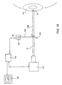
- Fig. 19 illustrates a laser beam 18 passing through an aperture 210 of an aperture wheel 200. As wheel 200 is rotated, laser beam 18 will pass through various apertures 220, 230 and 240. Each of apertures 210, 220, 230 and 240 may preferably be sized to different diameters such that different diameters of beam 18 can be selectively applied to the patient's cornea.
- the present invention provides systems which can determine the precise size and shape of beam 18 as it passes through each of apertures 210, 220, 230 and 240, as explained herein.
- laser beam spot shape and intensity profiles can be generated for use in sculpting the patient's cornea with a pattern of laser beam spots thereon.
- the targeting optics of the laser delivery system can be aligned to account for any offset between the actual position of the laser beam as determined by the present invention and the position of the laser beam as determined by the scanning hardware and galvanometers of the laser delivery system's targeting optics.
- a desired corneal ablation treatment can be effected without the laser beam shots becoming incident on undesired locations of target tissue or underablating intended targets thereby enhancing the accuracy of the resculpting algorithm and procedure.
- the laser beam spot is scanned along a path which passes over a knife-edge, (or any other such reference-edge), having a photodetector positioned therebehind.
- the laser beam is oriented perpendicular to the plane of the reference-edge during the scanning.
- the laser beam can be scanned across the reference-edge and onto the photodetector, or across the photodetector and onto the reference-edge.
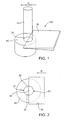
- Fig. 1 shows a perspective view of a laser beam 18 which is directed downwardly from a laser source (not shown) towards a reference-edge 30 and photodetector 40.
- Laser beam 18 is "scanned", (ie: moved across, while remaining generally perpendicular to), a reference-edge 30 and photodetector 40.
- An example of scanning is shown in Fig. 16 in which laser beam 18 is scanned across a measurement/alignment tool 100, which may comprise reference-edge 30 and photodetector 40.
- galvanometer 120 is rotated to scan laser beam 18 across the surface of alignment tool 100 from the position shown as beam 18A to the position shown as beam 18B.
- FIG. 1 shows a top plan view corresponding to Fig. 1 at the moment in time during the scanning where center 25 of laser beam spot 20 is positioned exactly at the edge of reference-edge 30.
- Fig. 2 shows a top plan view corresponding to Fig. 1 at the moment in time during the scanning where center 25 of laser beam spot 20 is positioned exactly at the edge of reference-edge 30.
- a first half 22 of laser beam spot 20 will be incident on photodetector 40 at the moment in time during the scanning where center 25 of laser beam spot 20 is positioned exactly over the edge of reference-edge 30.
- Figs. 3A, 3B, and 3C show the sequential movement of laser beam spot 20 as laser beam 18 is scanned across reference-edge 30 and onto photodetector 40 during the scanning.
- Fig. 4 shows the corresponding intensity of output signal S from photodetector 40 taken over time during the scanning of beam spot 20 across reference-edge 30 and onto photodetector 40.
- the intensity of output signal S of photodetector 40 will correspond to the area of beam spot 20 which is not blocked by reference-edge 30 and is therefore directly incident on photodetector 40.
- Points P1, P2 and P3 on Fig. 4 illustrate the intensity of output signal S at the moments in time when beam spot 20 is positioned as shown in Figs. 3A, 3B and 3C respectively.
- the intensity of output signal S will be in the shape of an S-shaped curve as shown in Fig. 4 , as follows.
- the photodetector When beam spot 20 is positioned fully over reference-edge 30 as is shown in Fig. 3A , the photodetector will typically emit only a small signal intensity N, representing noise in the system. As beam spot 20 is scanned across reference-edge 30, progressively more of the area of the beam spot 20 will reach photodetector 40, increasing the intensity of the photodetector's output signal S. When beam spot 20 reaches the position illustrated in Figs. 2 and 3B , such that center 25 of beam spot 20 is positioned directly at reference-edge 30, first half 22 of beam spot 20 will be incident upon the photodetector 40. Accordingly, signal S will reach approximately 1 ⁇ 2 of its maximum signal intensity at point P2. Finally, when beam spot 20 eventually reaches the position illustrated in Fig. 3C , at which the entire beam spot 20 is incident upon photodetector 40, signal S will reach its maximum signal intensity at point P3.
- the intensity of the laser beam 18 may be determined by measuring the maximum output signal of the photodetector at point P3 when the laser beam spot is fully incident on the photodetector and is not blocked by the reference-edge.
- the area of laser beam spot 20 may be determined by taking the integral of the area under curve S between points P1 and P3 since this area will correspond to the full area of beam spot 20 which becomes incident upon photodetector 40 from the beginning of the scanning as shown in Fig. 3A to the end of the scanning as shown in Fig. 3C .
- center 25 of laser spot beam may be determined.
- center 25 of laser beam spot 20 passes over reference-edge 30 when the intensity of output signal S reaches point P2, being 1 ⁇ 2 of the intensity of output signal S at point P3. Due to the presence of a small noise signal N at point P1, it may be difficult to determine when the output signal intensity is at point P2. Accordingly, in a preferred approach, P2 is found by determining a point midway between a first fraction of the maximum signal output and a second fraction of the maximum signal output, wherein the first and second fractions add together to the maximum signal output.
- a point P4 is located where the signal intensity equals 10% of the maximum signal output at point P3.
- a point P5 is located where the signal intensity equals 90% of the maximum signal output at point P3.
- point P2 is then located centrally therebetween. It is to be appreciated that points P4 and P5 could also be 30% and 70%, or 15% and 85%, or any other combination of respective percentages which add together to 100% of the maximum signal intensity at point P3.
- the speed of the scanning can be known either through position feedback systems or by determining the speed and time of the scanning. Knowing the speed of the scanning, (which corresponds to the rate of rotation of galvanometer 120), and determining the moment in time at which P2 is reached, (ie: when the center 25 of beam spot 20 is positioned at reference-edge 30), the location of center 25 is thus determined.
- the width of beam spot 20 in scanning direction D is determined as follows. Referring first to Fig. 3A , a leading edge 21 of beam spot 20 is positioned at reference-edge 30, (as represented by point P1 in Fig. 4 ). At the commencement of scanning, leading edge 21 will start to become incident upon photodetector 40, (as represented in Fig. 4 by the output signal intensity of the photodetector just beginning to increase). Referring to the end of the scanning as shown in Fig. 3C , a trailing edge 23 will become incident upon photodetector 40 as shown, (as represented by point P3 in Fig. 4 when the output signal intensity of the photodetector stops increasing).
- Knowing the speed of movement of laser beam scanning in direction D (either by knowing the speed and time during the scanning or through a position feedback system), the moments in time when P1 and P3 are reached can be determined. As such, the width of laser beam spot 20, (which begins its passage over photodetector 40 at point P1 and ends passage at point P3), can easily be calculated.
- the shape of the laser beam spot 20 is determined by measuring the rate of change of output signal S during the scanning.
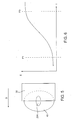
- Fig. 5 illustrates an oval shaped laser beam spot 20A being scanned across reference-edge 30 and photodetector 40.
- Laser beam spot 20A is elongated in direction D, as shown.
- the intensity of the output signal S corresponding to scanning laser beam spot 20A across reference-edge 30 and photodetector 40 is shown in Fig. 6 .
- the rate of change of the output signal S of photodetector 40 between points P1 and P3 is more gradual than was illustrated in Fig. 4 , (shown by the greater amount of time separating points P1 and P3 in Fig. 6 as compared to Fig. 4 ).
- the more gradual the rate of change of the output signal S in Fig. 6 thus indicates that laser beam spot 20A is more elongated in direction D than circular-shaped laser beam spot 20.
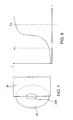
- Fig. 7 illustrates an oval beam spot 20B, being scanned across reference-edge 30 and photodetector 40.
- Laser beam spot 20B is elongated in a direction perpendicular to direction D. as shown.
- Fig. 8 shows the intensity of output signal S corresponding to the scanning of Fig. 7 .
- the rate of change of output signal S is much faster than was shown in Fig. 4 , (as shown by the smaller amount of time between points P1 and P3 in Fig. 8 as compared to Fig. 4 ).
- the faster rate of change of the output signal S in Fig. 8 thus indicates that laser beam spot 20B is more elongated in a direction perpendicular to direction D than circular-shaped laser beam spot 20.
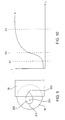
- the shape of laser beam spot 20 is determined by measuring the symmetry of output signal S during the scanning. As such, asymmetries and/or eccentricities of laser beam spot 20 are determined as follows. Referring to Fig. 9 , an eccentric exaggerated "teardrop-shaped" laser beam spot 20C is scanned across reference-edge 30 and photodetector 40. Using the novel approaches set out above, the leading edge 21C will be located at point P1, the spot center 25C will be located at point P2 and the trailing edge will be located at point P3 on Fig. 10 . As can be seen, point P2 (at Conversely, Fig. 7 illustrates an oval beam spot 20B, being scanned across reference-edge 30 and photodetector 40.
- Laser beam spot 20B is elongated in a direction perpendicular to direction D, as shown.
- Fig. 8 shows the intensity of output signal S corresponding to the scanning of Fig. 7 .
- the rate of change of output signal S is much faster than was shown in Fig. 4 , (as shown by the smaller amount of time between points P1 and P3 in Fig. 8 as compared to Fig. 4 ).
- the faster rate of change of the output signal S in Fig. 8 thus indicates that laser beam spot 20B is more elongated in a direction perpendicular to direction D than circular-shaped laser beam spot 20.
- the shape of laser beam spot 20 is determined by measuring the symmetry of output signal S during the scanning. As such, asymmetries and/or eccentricities of laser beam spot 20 are determined as follows. Referring to Fig. 9 , an eccentric exaggerated "teardrop-shaped" laser beam spot 20C is scanned across reference-edge 30 and photodetector 40. Using the novel approaches set out above, the leading edge 21C will be located at point P1, the spot center 25C will be located at point P2 and the trailing edge will be located at point P3 on Fig. 10 .
- point P2 (at which signal intensity is 1 ⁇ 2 of that at P3), is not centered between points P1 and P3, but rather is closer to P1, thus indicating that laser beam spot 20C has a somewhat eccentric shape with its center 25C being closer to leading edge 21C than to trailing edge 23C.
- Described above are systems for measuring the intensity, size and shape profiles of a laser beam spot in the direction in which it is scanned over a reference-edge and onto a photodetector.
- the size, shape and position of the laser beam spot may be determined in two directions, as follows. Referring to Fig. 11 , a beam spot 20 is moved in a first direction D1 across edge 31 followed by movement in a second perpendicular direction D2 across edge 33. In this illustration, edges 31 and 33 together form a corner to reference-edge 30.
- the positions of leading edge 21, trailing edge 23 and center 25 can be determined. Knowing the positions of leading edge 21 and trailing edge 23, width W1 in direction D1 can be calculated. Subsequently, laser beam spot 20 is scanned in perpendicular direction D2 across edge 33. As a result, the positions of side edges 27 and 29, and center 25 can be determined using the above described techniques. Knowing the positions of side edges 27 and 29, width W2 in direction D2 can then be calculated.
- Fig. 12 illustrates an arrangement similar to that of Fig. 11 , but instead using separate photodetectors 40A and 40B.
- Fig. 13 illustrates yet another arrangement, instead using two separate perpendicular reference-edges 32 and 34 and two separate photodetectors 40A and 40B positioned thereunder as shown.
- the laser beam can then be safely directed at target tissue in the cornea of a patient's eye, knowing the exact size and shape of the beam spot which will be incident upon the target tissue.
- the cornea can be sculpted to a desired shape by repeated application of the laser beam to a number of different sites in a pattern on the cornea.
- the size and shape of the laser beam spot can be precisely determined prior to, or concurrently with, successive applications of the laser beam to the cornea.
- laser beam 18 can be alternatingly re-directed between a calibration tool 100 and the patient's cornea 130.
- Calibration tool 100 may preferably comprise reference-edge 30 and photodetector 40 operating as described above.
- laser beam 18 can be repeatedly reflected as beam 18C by galvanometer 120 to a patient's cornea 130, (subsequently to the scanning of beam 18 across tool 100, from the position shown as beam 18A to 18B).
- tool 100 can instead be repeatedly moved back and forth to the position shown in phantom as tool 100A.
- laser beam 18 is periodically interrupted in its application on cornea 130 when tool 100 is positioned in the path of the laser beam to determine the intensity and shape profiles of laser beam spot 20.
- the process of repeatedly scanning beam 18 across alignment tool 100, or repeatedly removing and replacing tool 100 in the beam path, (thereby repeatedly determining the size and shape of laser beam spot 20), and then repeatedly re-sculpting cornea 130 by laser ablation ensures the size and shape of laser beam spot 20 do not change over time during the ablation of the patient's cornea.
- a beam splitter 250 can also be used to direct a first portion 19A of beam 18 to tool 100 while simultaneously directing a second portion 19B of beam 18 to cornea 130.
- a beam splitter 250 can also be used to direct a first portion 19A of beam 18 to tool 100 while simultaneously directing a second portion 19B of beam 18 to cornea 130.
- real time measurement of both intensity and shape profiles of beam spot 20 upon cornea 130 can be achieved while the tissues of the cornea are ablated.
- a computer 124 to record the intensity of the output signal of photodetector 40 over time, thereby generating both intensity and shape profiles of laser beam spot 20.
- computer 124 is adapted to calculate preferred patterns of laser beam spot application on cornea 130 from the intensity and shape profiles of laser beam spot 20. As such, cornea 130 can sculpted to a desired shape.
- a monitor 126 is adapted to display a waveform representing the intensity of the output signal of photodetector 40 over time.
- tool 100 can be used to align the targeting optics of the laser delivery system. Specifically, after locating center 25 of laser beam spot 20 as it is scanned across photodetector 40, the beam delivery system (including galvanometer 120) can be precisely aligned to compensate for any difference between the position of the laser beam as determined by targeting optics 122, and that indicated by tool 100.
- a suitable material for tool 100 which fluoresces but does not ablate is preferred. Such material may comprise a white stock paper or a white business card. Also, a suitable fluorescent plate material which can be purchased from Startech Inc, of Connecticut can be used.
- measurement/alignment tool 100 comprises a screen 105 which fluoresces in response to laser light incident thereon, as illustrated in Figs. 14 to 15B .
- laser beam 18 is directed incident to screen 105, causing screen 105 to fluoresce in the region of beam spot 20.
- Targeting optics 122 displays a reticle 110 to operator 200, and the operator adjusts the laser beam delivery optics so that the fluorescing beam spot is aligned with the reticle.
- adjusting the location of beam spot 20 can be effected using the beam scanning mechanism. This may significantly facilitate alignment, as the system microscope need not be moved with a precise X-Y adjustment mechanism. Instead, the targeting signals transmitted to the galvanometric laser beam delivery optics can be selectively altered or offset to aim the beam tat the target location. Scanned accuracy may be enhanced by moving the beam between a plurality of target locations, and by individual beam shot targets using the signal offsets throughout the resculpting procedure. In alternative embodiments, the beam delivery optics may be mechanically adjusted to move beam spot 20 between the cross-hairs of reticle 110, thereby aligning the targeting optics of the laser beam delivery system.
- tool 100 may be removably positioned at or near the location which will be occupied by the eye during refractive resculpting.
- Tool 100 may be held by a swing-away arm or the like in a conventional manner.
- the operator enters an alignment mode. In this mode, reticle 110 remains stationary, and the laser fires to induce fluorescence at beam spot 20.
- the beam spot may be moved by the operator via an input device such as a joystick, mouse, switches, or the like which adjusts the beam delivery optics by changing the signal sent to the galvanometers.
- the laser beam would again fire producing a new laser spot 20, and the operator would continue to adjust the signal offsets until the laser beam is coincident with the laser beam.
- the operator can press a button (or provide any alternative signal to the system) and the system computer will then store the offset signals for determining the ablation center.
- the reticle will also be used to align the eye with the system after the tool is moved out of the way.
Description
- The present invention relates to calibration techniques for determining the characteristics of a laser beam, particularly for use with laser eye surgery systems. More specifically, the invention provides a method and apparatus for determining a characteristic of a laser beam such as the dimensions and/or position of the laser beam spot upon a target, and can provide input for generating, verifying, or adjusting ablation algorithms used to plan a resculpting procedure. When used in conjunction with laser eye surgery systems, the present invention can assist in determining patterns of laser beam spot delivery upon a patient's cornea, and can also be used in calibrating the laser beam delivery system.
- When performing laser eye surgery such as when ablating a target region on a patient's cornea with a refractive laser beam system, it is beneficial to have accurate information on the dimensions of the laser beam spot which is incident on the cornea. Deviation from a desired spot size and shape, such as by increased or decreased diameter of the laser beam spot or by the spot exhibiting an oval or non-symmetrical shape, could result in tissue ablation at undesired locations on the patient's corneas with each laser pulse, leading to less than ideal resculpting. Inaccuracy in the location of the laser spots may result in off-center ablations.
-
US-A-5258821 describes a laser beam profiler having a multimode laser diode interferometer. The profile of the laser beam is measured using a knife-edge plate and photodetector assembly. -
EP-A-0319345 describes a high power laser intensity mapping apparatus in which the beam to be examined is directed towards two knife-edge mirrors arranged to pass only a thin vertical segment of the beam and to reflect the remainder of the beam to power absorbers. -
US-A-5267012 describes apparatus for measuring the low quality of a laser beam in which the beam is chopped using a rotating hub having apertures for selectively passing the beam. - In a first aspect, the present invention provides a method as set out in
claim 1. In another aspect, the present invention provides apparatus as set out in claim 11. Embodiments of the present invention provide methods and apparati for determining characteristics of a laser beam spot, the characteristics typically including the intensity, dimensions, and/or position of the laser beam spot. An advantage of the present invention is that it can be used with laser eye surgery systems such that the dimensions of the laser beam spot, (including its diameter, area and eccentricity), can be precisely determined prior to, or concurrently with, the laser beam spot being used to ablate a region of the patient's cornea. - In described methods, a laser beam is scanned in a path across a reference-edge, (which may preferably comprise a knife-edge), having a photodetector positioned therebehind, with the laser beam preferably remaining in a path generally perpendicular to the plane of the reference-edge during the scanning.
- An output signal is generated by the photodetector corresponding to a percentage of the laser beam which is actually incident on the photodetector, (ie: not blocked by the reference-edge), at various moments in time during the scanning of the laser beam. For a beam having a uniform energy distribution, the percentage of the laser beam energy which is incident on the photodetector will correspond to the area of the laser beam spot which is incident on the photodetector. By measuring the output signal characteristics of the photodetector during the scanning, the present invention provides systems for determining the size and shape of the laser beam spot as well as the intensity of the laser beam. In preferred aspects, a computer calculates the intensity and shape profiles of the laser beam from the photodetector output signals.
- As stated, the output signal generated by the photodetector will correspond to the size of the area of the laser beam spot incident thereon. As such, when the laser beam is fully incident on the reference-edge, (ie: when it is blocked from reaching the photodetector by the reference-edge), the photodetector will generate no output signal, or it will only generate a minimal output signal as a result of noise. Conversely, when the laser beam spot has been scanned completely across the reference-edge and is then fully incident on the photodetector, the photodetector will generate a maximum output signal.
- The larger the area of the laser beam spot incident upon the photodetector, the stronger the output signal generated by the photodetector. Accordingly, in a preferred aspect of the invention, the intensity of the laser beam is determined by measuring the maximum output signal of the photodetector when the laser beam spot is fully incident on the photodetector and is not blocked by the reference-edge.
- The total area of the laser beam spot may be determined by integrating the area under a curve representing the intensity of the photodetector signal output during the scanning as the laser beam is scanned across the reference-edge.
- The position of the center of the laser beam spot may be located by determining when the output signal of the photodetector reaches half of its maximum output signal during the scanning, thus indicating that the center of the laser beam spot is positioned directly at the edge of the reference-edge, (with one half of the laser beam spot incident on the photodetector and one The larger the area of the laser beam spot incident upon the photodetector, the stronger the output signal generated by the photodetector. Accordingly, the intensity of the laser beam may be determined by measuring the maximum output signal of the photodetector when the laser beam spot is fully incident on the photodetector and is not blocked by the reference-edge.
- The total area of the laser beam spot may be determined by integrating the area under a curve representing the intensity of the photodetector signal output during the scanning as the laser beam is scanned across the reference-edge.
- The position of the center of the laser beam spot may be located by determining when the output signal of the photodetector reaches half of its maximum output signal during the scanning, thus indicating that the center of the laser beam spot is positioned directly at the edge of the reference-edge, (with one half of the laser beam spot incident on the photodetector and one half of the laser beam spot incident on the reference-edge).
- The width of he laser beam spot in the direction of the path of the scanning may be determined by locating the positions of the leading and trailing edges of the laser beam spot and then determining a spacing therebetween. The leading edge of the laser beam spot may be located by determining when the photodetector begins to emit an output signal, (being indicative of the laser beam spot leading edge first passing over the reference-edge and becoming incident on the photodetector). The trailing edge of the laser beam spot is located by determining when the output signal of the photodetector has reached a maximum (indicating that the laser beam spot is not blocked by the reference-edge and is therefore fully incident on the photodetector). After determining the moments in time when the leading and trailing edges of the laser beam spot pass over the reference-edge as set out above, the width of the laser beam spot in the direction of the scanning is calculated based upon the speed of the laser beam scanning across the reference-edge.
- The width of the laser beam spot in the direction of the path of the scanning may be determined by locating the positions of the leading and trailing edges of the laser beam spot and then determining a spacing therebetween. The leading edge of the laser beam spot may be located by determining when the photodetector begins to emit an output signal, (being indicative of the laser beam spot leading edge first passing over the reference-edge and becoming incident on the photodetector). The trailing edge of the laser beam spot is located by determining when the output signal of the photodetector has reached a maximum (indicating that the laser beam spot is not blocked by the reference-edge and is therefore fully incident on the photodetector). After determining the moments in time when the leading and trailing edges of the laser beam spot pass over the reference-edge as set out above, the width of the laser beam spot in the direction of the scanning is calculated based upon the speed of the laser beam scanning across the reference-edge.
- Asymmetries and eccentricities in the laser beam spot are found by measuring the rate of change or the symmetry of the rate of change of the output signal during the scanning.
- The size, shape and position of the laser beam spot may be determined in two directions which are preferably perpendicular to one another. In this aspect of the invention, scanning is preferably performed in two perpendicular paths, over perpendicular first and second reference-edges. The size, shape and position of the laser beam may be determined in the two perpendicular directions by measuring the output signals from either a single photodetector or two separate photodetectors positioned behind the reference-edges. An advantage of this is that asymmetries of the beam spot (ie: an irregular shape of the beam spot) as well as eccentricities of the beam spot (ie: elongation of the beam spot to form an oval-shape), can be detected.
- The photodetector may be a bulk detector. As such, an advantage is that a more complex and expensive imaging detector is not required.
- Also described are methods of calibrating scanning laser beam delivery system. These methods comprise positioning a calibration tool at a target location; directing the laser beam onto the tool; sensing the laser beam using the tool; and adjusting the system in response to the sensed laser beam. In various aspects, the laser beam can be repeatedly re-directed, (for example, by a galvanometric mirror), between the tool and a patient's cornea. As such, after determining the size, shape and/or position of the beam, the laser beam can be applied at a known location on the cornea. Alternatively, the tool can be repeatedly inserted into and removed from the beam path between the laser beam source and the patient's cornea. As such, the alignment tool can then be repeatedly removed from the target location to allow for resculpting of the patient's cornea and then replaced at the target location after the resculpting of the cornea. Using either approach, a repetitive measurement of intensity and shape characteristics of the laser beam can be made as well as repetitive recallibration of the targeting of the laser beam can be achieved, thus ensuring precise positional accuracy when ablating the patient's cornea.
- Splitting the laser beam with a first portion of the beam directed to the measurement/alignment tool and a second portion directed to the patient's cornea such that real time measurement of shape and intensity characteristics of the laser beam spot and/or real time alignment of the laser beam delivery system can be achieved.
- Regardless of the tool positioning, the calibration tool will often provide signals indicating beam spot size, shape, energy distribution, and/or location. These signals may be used to adjust the planned ablation protocol of the beam delivery system. Specifically, using the sensed information, an algorithm for calculating the locations and number of shots can be revised, thereby increasing the accuracy of the resculpting procedure. This calibration information can be used to adjust the ablation algorithm immediately before and/or during each ablation procedure.
- The measuring/alignment tool may comprise a target which fluoresces in response to laser light incident thereon. In this second embodiment of the invention, an operator views the position of the fluoresced spot on the target screen while directing laser light at the target screen. Such viewing may preferably be done through the system microscope. The beam delivery system is aligned with the targeting optics, which may comprise a cross-hair reticle, thereby calibrating the laser beam delivery system.
-
-
Fig. 1 is a perspective view of a laser beam being scanned over a reference-edge having a photodetector positioned therebehind at the moment in time when the laser beam is centered over the reference-edge. -
Fig. 2 is a top plan view corresponding toFig. 1 . -
Fig. 3A, 3B and 3C are sequential illustrations of the laser beam moving across the reference-edge ofFigs. 1 and 2 . -
Fig. 4 is a graph of the output signal of the photodetector during the scanning illustrated inFigs. 3A, 3B and 3C . -
Fig. 5 is a view of an oval shaped laser beam spot, (having a major axis parallel to the path of the scanning), being scanned over a reference-edge with a photodetector positioned therebehind. -
Fig. 6 is a representation of the output signal of the photodetector during a scanning of the oval shaped laser beam spot ofFig. 5 . -
Fig. 7 is a plan view of an oval shaped laser beam spot, (having a major axis perpendicular to the path of the scanning), being scanned over a reference-edge with a photodetector therebehind. -
Fig. 8 is a representation of the output signal of the photodetector during a scanning of the oval shaped laser beam spot ofFig. 7 . -
Fig. 9 is a plan view of an eccentric shaped laser beam spot being scanned over a reference-edge with a photodetector therebehind. -
Fig. 10 is a representation of the output signal of the photodetector during a scanning of the oval shaped laser beam spot ofFig. 9 . -
Fig. 11 is a top plan view of a laser beam spot being scanned over two perpendicular reference-edges wherein the two reference-edges together form a corner of a planar member. -
Fig. 12 corresponds toFig. 11 , but instead uses two separated photodetectors. -
Fig. 13 is a top plan view showing a laser beam scanning over two perpendicular reference-edges, each reference-edge having a separate photodetector positioned therebehind. -
Fig. 14 is a perspective view of the laser beam delivery system directing a laser beam at a screen which fluoresces in the region where the laser beam is incident thereon. -
Fig. 15A is a view through the targeting optics of the laser beam delivery system prior to system calibration when the laser beam is directed to the fluorescing screen ofFig. 14 . -
Fig. 15B is a view corresponding toFig. 15A , after system calibration. -
Fig. 16 is an illustration of the laser beam delivery system scanning a laser beam across a calibration tool and applying a therapeutic laser beam to a patient's cornea. -
Fig. 17 is an illustration of the laser beam delivery system applying a therapeutic laser beam to a patient's cornea showing a removable calibration tool in the beam path. -
Fig. 18 is an illustration of the laser beam delivery system simultaneously applying a therapeutic laser beam to a patient's cornea and to a calibration tool. -
Fig. 19 is an illustration of the laser beam delivery system directing a laser beam through selectable apertures of an aperture wheel or turret. -
Figs. 1 to 13 illustrate various aspects of a first embodiment of the present invention.Figs. 14 to 15B illustrate various aspects of a second embodiment of the present invention.Figs. 16 to 20 illustrate calibration systems which include a calibration tool which may comprise the first or second embodiment of the present invention. - When targeting an excimer laser beam to ablate regions of a patient's cornea during laser eye surgery, the spot formed by the laser beam upon the target will often have a circular shape, and will typically be intended to have a substantially uniform energy distribution. Other known beam delivery systems have rectangular or slit-shaped beams, optionally with Gaussian or other uneven energy profiles. Regardless, the exact intensity and shape profiles of the laser beam spot can not always be determined relying upon th targeting optics of the laser delivery system alone. It is beneficial to know the intensity and shape profiles of the laser beam as accurately as possible, especially when generating a pattern of laser beam spot application to the patient's cornea. Having accurate intensity and shape profile for the laser beam spot, it is possible to accurately sculpt the patient's cornea through successive application of a laser beam in a pattern of spots on the cornea. The present invention provides accurate determination of intensity and shape profiles of the laser beam spot which can be used to generate targeting patterns, and to otherwise calibrate the system.
- The laser system may include, but is not limited to, an excimer laser such as an argon-fluoride excimer laser producing laser energy with a wavelength of about 193 nm. Alternative laser systems may include solid state lasers, such as frequency multiplied solid state lasers, flash-lamp and diode pumped solid state lasers, and the like. Exemplary solid state lasers include UV solid state lasers producing wavelengths of approximately 193-215 nm such as those disclosed in
U.S. Patent Nos. 5,144,630 , and5,742,626 , and in Borsuztky et al., "Tunable UV Radiation at Short Wavelengths (188-240 nm) Generated by Frequency Mixing in Lithium Borate", Appl. Phys. 61:529-532 (1995). A variety of alternative lasers might also be used. The laser energy will often comprise a beam formed as a series of discreet laser pulses or shots. - The exact diameter and shape of the laser beam spot upon a target can not always be precisely determined relying upon the targeting system optics alone. This is especially true if the shape of the laser beam spot is somewhat eccentric or asymmetrical. Moreover, minor changes in the size and shape of the laser beam spot can be introduced when switching between different apertures and lenses in the laser delivery system. For example,
Fig. 19 illustrates alaser beam 18 passing through anaperture 210 of anaperture wheel 200. Aswheel 200 is rotated,laser beam 18 will pass throughvarious apertures apertures beam 18 can be selectively applied to the patient's cornea. The present invention provides systems which can determine the precise size and shape ofbeam 18 as it passes through each ofapertures - Described herein are methods and apparati for precisely determining dimensions including the size, shape and position of the laser beam spot upon the target. Accordingly, laser beam spot shape and intensity profiles can be generated for use in sculpting the patient's cornea with a pattern of laser beam spots thereon. Also, the targeting optics of the laser delivery system can be aligned to account for any offset between the actual position of the laser beam as determined by the present invention and the position of the laser beam as determined by the scanning hardware and galvanometers of the laser delivery system's targeting optics. By determining the exact size, shape and intensity of the laser beam spot with the present invention, a desired corneal ablation treatment can be effected without the laser beam shots becoming incident on undesired locations of target tissue or underablating intended targets thereby enhancing the accuracy of the resculpting algorithm and procedure.
- As set out in
Figs. 1 to 13 , the laser beam spot is scanned along a path which passes over a knife-edge, (or any other such reference-edge), having a photodetector positioned therebehind. Preferably, the laser beam is oriented perpendicular to the plane of the reference-edge during the scanning. In various approaches, the laser beam can be scanned across the reference-edge and onto the photodetector, or across the photodetector and onto the reference-edge. - By measuring the output of the photodetector, it is possible to determine the intensity, size, shape and position of the laser beam spot during the scanning, as follows.
-
Fig. 1 shows a perspective view of alaser beam 18 which is directed downwardly from a laser source (not shown) towards a reference-edge 30 andphotodetector 40.Laser beam 18 is "scanned", (ie: moved across, while remaining generally perpendicular to), a reference-edge 30 andphotodetector 40. An example of scanning is shown inFig. 16 in whichlaser beam 18 is scanned across a measurement/alignment tool 100, which may comprise reference-edge 30 andphotodetector 40. Specifically,galvanometer 120 is rotated to scanlaser beam 18 across the surface ofalignment tool 100 from the position shown asbeam 18A to the position shown asbeam 18B. - Returning to
Fig. 1 ,laser beam 18 is thus scanned across reference-edge 30 andphotodetector 40 indirection D. Photodetector 40, (which may preferably comprise a bulk photodetector), is positioned behind reference-edge 30 as shown.Fig. 2 shows a top plan view corresponding toFig. 1 at the moment in time during the scanning wherecenter 25 oflaser beam spot 20 is positioned exactly at the edge of reference-edge 30. As can be seen, shouldlaser beam spot 20 have a circular shape as illustrated, afirst half 22 oflaser beam spot 20 will be incident onphotodetector 40 at the moment in time during the scanning wherecenter 25 oflaser beam spot 20 is positioned exactly over the edge of reference-edge 30. -
Figs. 3A, 3B, and 3C show the sequential movement oflaser beam spot 20 aslaser beam 18 is scanned across reference-edge 30 and ontophotodetector 40 during the scanning.Fig. 4 shows the corresponding intensity of output signal S fromphotodetector 40 taken over time during the scanning ofbeam spot 20 across reference-edge 30 and ontophotodetector 40. The intensity of output signal S ofphotodetector 40 will correspond to the area ofbeam spot 20 which is not blocked by reference-edge 30 and is therefore directly incident onphotodetector 40. Specifically, the intensity of signal S can be represented for a Gaussian pulse as follows:
or for a "top hat" pulse, (in which the energy distribution is substantially uniform across the cross-section of the pulse), as follows:
- Points P1, P2 and P3 on
Fig. 4 illustrate the intensity of output signal S at the moments in time whenbeam spot 20 is positioned as shown inFigs. 3A, 3B and 3C respectively. For a generallycircular beam spot 20, the intensity of output signal S will be in the shape of an S-shaped curve as shown inFig. 4 , as follows. - When
beam spot 20 is positioned fully over reference-edge 30 as is shown inFig. 3A , the photodetector will typically emit only a small signal intensity N, representing noise in the system. Asbeam spot 20 is scanned across reference-edge 30, progressively more of the area of thebeam spot 20 will reachphotodetector 40, increasing the intensity of the photodetector's output signal S. Whenbeam spot 20 reaches the position illustrated inFigs. 2 and3B , such thatcenter 25 ofbeam spot 20 is positioned directly at reference-edge 30,first half 22 ofbeam spot 20 will be incident upon thephotodetector 40. Accordingly, signal S will reach approximately ½ of its maximum signal intensity at point P2. Finally, whenbeam spot 20 eventually reaches the position illustrated inFig. 3C , at which theentire beam spot 20 is incident uponphotodetector 40, signal S will reach its maximum signal intensity at point P3. - The intensity of the
laser beam 18 may be determined by measuring the maximum output signal of the photodetector at point P3 when the laser beam spot is fully incident on the photodetector and is not blocked by the reference-edge. - The area of
laser beam spot 20 may be determined by taking the integral of the area under curve S between points P1 and P3 since this area will correspond to the full area ofbeam spot 20 which becomes incident uponphotodetector 40 from the beginning of the scanning as shown inFig. 3A to the end of the scanning as shown inFig. 3C . - The location of
center 25 of laser spot beam may be determined. As explained above,center 25 oflaser beam spot 20 passes over reference-edge 30 when the intensity of output signal S reaches point P2, being ½ of the intensity of output signal S at point P3. Due to the presence of a small noise signal N at point P1, it may be difficult to determine when the output signal intensity is at point P2. Accordingly, in a preferred approach, P2 is found by determining a point midway between a first fraction of the maximum signal output and a second fraction of the maximum signal output, wherein the first and second fractions add together to the maximum signal output. - For example, a point P4 is located where the signal intensity equals 10% of the maximum signal output at point P3. Similarly, a point P5 is located where the signal intensity equals 90% of the maximum signal output at point P3. After locating points P4 and P5 on the signal curve, point P2 is then located centrally therebetween. It is to be appreciated that points P4 and P5 could also be 30% and 70%, or 15% and 85%, or any other combination of respective percentages which add together to 100% of the maximum signal intensity at point P3.
- The speed of the scanning can be known either through position feedback systems or by determining the speed and time of the scanning. Knowing the speed of the scanning, (which corresponds to the rate of rotation of galvanometer 120), and determining the moment in time at which P2 is reached, (ie: when the
center 25 ofbeam spot 20 is positioned at reference-edge 30), the location ofcenter 25 is thus determined. - In another preferred aspect of the present invention, the width of
beam spot 20 in scanning direction D is determined as follows. Referring first toFig. 3A , a leadingedge 21 ofbeam spot 20 is positioned at reference-edge 30, (as represented by point P1 inFig. 4 ). At the commencement of scanning, leadingedge 21 will start to become incident uponphotodetector 40, (as represented inFig. 4 by the output signal intensity of the photodetector just beginning to increase). Referring to the end of the scanning as shown inFig. 3C , a trailingedge 23 will become incident uponphotodetector 40 as shown, (as represented by point P3 inFig. 4 when the output signal intensity of the photodetector stops increasing). - Knowing the speed of movement of laser beam scanning in direction D, (either by knowing the speed and time during the scanning or through a position feedback system), the moments in time when P1 and P3 are reached can be determined. As such, the width of
laser beam spot 20, (which begins its passage overphotodetector 40 at point P1 and ends passage at point P3), can easily be calculated. - According to the invention, the shape of the
laser beam spot 20 is determined by measuring the rate of change of output signal S during the scanning. - For example,
Fig. 5 illustrates an oval shapedlaser beam spot 20A being scanned across reference-edge 30 andphotodetector 40.Laser beam spot 20A is elongated in direction D, as shown. The intensity of the output signal S corresponding to scanninglaser beam spot 20A across reference-edge 30 andphotodetector 40 is shown inFig. 6 . As can be seen, the rate of change of the output signal S ofphotodetector 40 between points P1 and P3 is more gradual than was illustrated inFig. 4 , (shown by the greater amount of time separating points P1 and P3 inFig. 6 as compared toFig. 4 ). The more gradual the rate of change of the output signal S inFig. 6 thus indicates thatlaser beam spot 20A is more elongated in direction D than circular-shapedlaser beam spot 20. - Conversely.
Fig. 7 illustrates anoval beam spot 20B, being scanned across reference-edge 30 andphotodetector 40.Laser beam spot 20B is elongated in a direction perpendicular to direction D. as shown.Fig. 8 shows the intensity of output signal S corresponding to the scanning ofFig. 7 . As can be seen, the rate of change of output signal S is much faster than was shown inFig. 4 , (as shown by the smaller amount of time between points P1 and P3 inFig. 8 as compared toFig. 4 ). The faster rate of change of the output signal S inFig. 8 thus indicates thatlaser beam spot 20B is more elongated in a direction perpendicular to direction D than circular-shapedlaser beam spot 20. - The shape of
laser beam spot 20 is determined by measuring the symmetry of output signal S during the scanning. As such, asymmetries and/or eccentricities oflaser beam spot 20 are determined as follows. Referring toFig. 9 , an eccentric exaggerated "teardrop-shaped"laser beam spot 20C is scanned across reference-edge 30 andphotodetector 40. Using the novel approaches set out above, theleading edge 21C will be located at point P1, thespot center 25C will be located at point P2 and the trailing edge will be located at point P3 onFig. 10 . As can be seen, point P2 (at Conversely,Fig. 7 illustrates anoval beam spot 20B, being scanned across reference-edge 30 andphotodetector 40.Laser beam spot 20B is elongated in a direction perpendicular to direction D, as shown.Fig. 8 shows the intensity of output signal S corresponding to the scanning ofFig. 7 . As can be seen, the rate of change of output signal S is much faster than was shown inFig. 4 , (as shown by the smaller amount of time between points P1 and P3 inFig. 8 as compared toFig. 4 ). The faster rate of change of the output signal S inFig. 8 thus indicates thatlaser beam spot 20B is more elongated in a direction perpendicular to direction D than circular-shapedlaser beam spot 20. - The shape of
laser beam spot 20 is determined by measuring the symmetry of output signal S during the scanning. As such, asymmetries and/or eccentricities oflaser beam spot 20 are determined as follows. Referring toFig. 9 , an eccentric exaggerated "teardrop-shaped"laser beam spot 20C is scanned across reference-edge 30 andphotodetector 40. Using the novel approaches set out above, theleading edge 21C will be located at point P1, thespot center 25C will be located at point P2 and the trailing edge will be located at point P3 onFig. 10 . As can be seen, point P2 (at which signal intensity is ½ of that at P3), is not centered between points P1 and P3, but rather is closer to P1, thus indicating thatlaser beam spot 20C has a somewhat eccentric shape with itscenter 25C being closer to leadingedge 21C than to trailingedge 23C. - Described above are systems for measuring the intensity, size and shape profiles of a laser beam spot in the direction in which it is scanned over a reference-edge and onto a photodetector.
- The size, shape and position of the laser beam spot may be determined in two directions, as follows. Referring to
Fig. 11 , abeam spot 20 is moved in a first direction D1 acrossedge 31 followed by movement in a second perpendicular direction D2 acrossedge 33. In this illustration, edges 31 and 33 together form a corner to reference-edge 30. - Measuring the output signal of
photodetector 40 aslaser beam spot 20 is scanned acrossedge 31 using the above described techniques, the positions of leadingedge 21, trailingedge 23 andcenter 25 can be determined. Knowing the positions of leadingedge 21 and trailingedge 23, width W1 in direction D1 can be calculated. Subsequently,laser beam spot 20 is scanned in perpendicular direction D2 acrossedge 33. As a result, the positions of side edges 27 and 29, andcenter 25 can be determined using the above described techniques. Knowing the positions of side edges 27 and 29, width W2 in direction D2 can then be calculated. -
Fig. 12 illustrates an arrangement similar to that ofFig. 11 , but instead usingseparate photodetectors Fig. 13 illustrates yet another arrangement, instead using two separate perpendicular reference-edges 32 and 34 and twoseparate photodetectors - After determining the size and shape of
laser beam spot 20 uponphotodetector 40. the laser beam can then be safely directed at target tissue in the cornea of a patient's eye, knowing the exact size and shape of the beam spot which will be incident upon the target tissue. Preferably, the cornea can be sculpted to a desired shape by repeated application of the laser beam to a number of different sites in a pattern on the cornea. The size and shape of the laser beam spot can be precisely determined prior to, or concurrently with, successive applications of the laser beam to the cornea. - For example, as shown in
Figs. 16 and17 ,laser beam 18 can be alternatingly re-directed between acalibration tool 100 and the patient'scornea 130.Calibration tool 100 may preferably comprise reference-edge 30 andphotodetector 40 operating as described above. Referring toFig. 16 ,laser beam 18 can be repeatedly reflected asbeam 18C bygalvanometer 120 to a patient'scornea 130, (subsequently to the scanning ofbeam 18 acrosstool 100, from the position shown asbeam 18A to 18B). Referring toFig. 17 ,tool 100 can instead be repeatedly moved back and forth to the position shown in phantom astool 100A. As such,laser beam 18 is periodically interrupted in its application oncornea 130 whentool 100 is positioned in the path of the laser beam to determine the intensity and shape profiles oflaser beam spot 20. The process of repeatedly scanningbeam 18 acrossalignment tool 100, or repeatedly removing and replacingtool 100 in the beam path, (thereby repeatedly determining the size and shape of laser beam spot 20), and then repeatedlyre-sculpting cornea 130 by laser ablation ensures the size and shape oflaser beam spot 20 do not change over time during the ablation of the patient's cornea. - As illustrated in
Fig. 18 , abeam splitter 250 can also be used to direct afirst portion 19A ofbeam 18 totool 100 while simultaneously directing asecond portion 19B ofbeam 18 tocornea 130. Using the arrangement ofFig. 18 , real time measurement of both intensity and shape profiles ofbeam spot 20 uponcornea 130 can be achieved while the tissues of the cornea are ablated. - Also shown in
Figs. 16 ,17 and18 are acomputer 124 to record the intensity of the output signal ofphotodetector 40 over time, thereby generating both intensity and shape profiles oflaser beam spot 20. Additionally,computer 124 is adapted to calculate preferred patterns of laser beam spot application oncornea 130 from the intensity and shape profiles oflaser beam spot 20. As such,cornea 130 can sculpted to a desired shape. Additionally, amonitor 126 is adapted to display a waveform representing the intensity of the output signal ofphotodetector 40 over time. - In another preferred aspect,
tool 100 can be used to align the targeting optics of the laser delivery system. Specifically, after locatingcenter 25 oflaser beam spot 20 as it is scanned acrossphotodetector 40, the beam delivery system (including galvanometer 120) can be precisely aligned to compensate for any difference between the position of the laser beam as determined by targetingoptics 122, and that indicated bytool 100. A suitable material fortool 100 which fluoresces but does not ablate is preferred. Such material may comprise a white stock paper or a white business card. Also, a suitable fluorescent plate material which can be purchased from Startech Inc, of Connecticut can be used. - In a second example, measurement/
alignment tool 100 comprises ascreen 105 which fluoresces in response to laser light incident thereon, as illustrated inFigs. 14 to 15B . Referring toFig. 14 ,laser beam 18 is directed incident to screen 105, causingscreen 105 to fluoresce in the region ofbeam spot 20. Anoperator 200 looking through targetingoptics 122, (which preferably comprises a system microscope), views fluorescing ofbeam spot 20, as shown inFig. 15A . Targetingoptics 122 displays areticle 110 tooperator 200, and the operator adjusts the laser beam delivery optics so that the fluorescing beam spot is aligned with the reticle. - Advantageously, adjusting the location of
beam spot 20 can be effected using the beam scanning mechanism. This may significantly facilitate alignment, as the system microscope need not be moved with a precise X-Y adjustment mechanism. Instead, the targeting signals transmitted to the galvanometric laser beam delivery optics can be selectively altered or offset to aim the beam tat the target location. Scanned accuracy may be enhanced by moving the beam between a plurality of target locations, and by individual beam shot targets using the signal offsets throughout the resculpting procedure. In alternative embodiments, the beam delivery optics may be mechanically adjusted to movebeam spot 20 between the cross-hairs ofreticle 110, thereby aligning the targeting optics of the laser beam delivery system. - In some examples,
tool 100 may be removably positioned at or near the location which will be occupied by the eye during refractive resculpting.Tool 100 may be held by a swing-away arm or the like in a conventional manner. To set or check the system prior to a resculpting procedure, the operator enters an alignment mode. In this mode,reticle 110 remains stationary, and the laser fires to induce fluorescence atbeam spot 20. The beam spot may be moved by the operator via an input device such as a joystick, mouse, switches, or the like which adjusts the beam delivery optics by changing the signal sent to the galvanometers. The laser beam would again fire producing anew laser spot 20, and the operator would continue to adjust the signal offsets until the laser beam is coincident with the laser beam. When coincidence is achieved, the operator can press a button (or provide any alternative signal to the system) and the system computer will then store the offset signals for determining the ablation center. Typically, the reticle will also be used to align the eye with the system after the tool is moved out of the way. - While the exemplary embodiments have been described in detail for clarity of understanding and by way of example, a variety of changes, adaptations, and modifications will be obvious for those of skill in the art. For example, a variety of scanning beam delivery systems might be used, including scanning systems which have a lens that may be variably offset from the beam axis or axes to image one or more laser beams at a laterally offset target location. The invention might be used with a wide variety of ablation planning protocols or algorithms, and provides input to such algorithms which can enhance their accuracy. Hence, the scope of the invention is limited solely by the appended claims.
Claims (22)
- A method of determining a characteristic of a laser beam, comprising:scanning the laser beam in a first path across a first reference-edge (31), having a photodetector device (40) positioned therebehind; andmeasuring an output signal from the photodetector device during the scanning, the output signal corresponding to an area of the laser beam incident on the first photodetector during the scanning, the method further comprising determining the width of the laser beam in the direction of the path of the scanning by:locating a leading edge of the laser beam by determining when the photodetector begins to emit an output signal indicative of the laser beam being incident thereon;locating a trailing edge of the laser beam by determining when the output signal of the photodetector reaches a maximum output signal; anddetermining a spacing between the leading edge and the trailing edge of the laser beam and the method further comprising determining the shape of the laser beam in the direction of the path of scanning by measuring the symmetry of the rate of change of the output signal during the scanning.
- The method of claim 1, wherein the photodetector device is provided by first and second photodetectors (40a and 40b) and the method further comprises:scanning the laser beam in a second path across a second reference-edge (33) having the second photodetector (40b) positioned therebehind, wherein the first reference-edge (31) is disposed at an angle to the second reference-edge (33), andmeasuring output signals from the first and second photodetector (40a and 40b) during the scanning, the output signals corresponding to an area of the laser beam incident on the first and second photodetectors during the scanning.
- The method of claim 1, wherein the photodetector device is provided by a single photodetector (40) and the method further comprises scanning the laser beam in a second path across a second reference-edge (33), wherein the photodetector (40) is positioned behind the first and second reference-edges (31 and 33), and wherein the first and second reference-edges (31 and 33) are disposed at an angle to one another, and measuring an output signal from the photodetector during the scanning, the output signal corresponding to an area of the laser beam incident on the photodetector during the scanning.
- The method as in claim 2 or 3, wherein the first reference-edge (31) and the second reference-edge (33) together comprise a corner of a planar member.
- The method as in any one of claims 1-3, further comprising determining dimensions of the laser beam spot by integrating the intensity of the photodetector signal output during the scanning.
- The method as in any one of claims 1-3, further comprising locating the center of the laser beam by determining when the output signal of the photodetector device reaches half of the maximum output signal strength during the scanning.
- The method as in any one of claims 1-3, further comprising locating the center of the laser beam by determining when the output signal of the photodetector device reaches a mid-point signal strength half-way between a first fraction of the maximum signal strength and a second fraction of the maximum signal strength, wherein the first and second fractions of the maximum signal strength add together to equal the maximum signal strength.
- The method of claim 7, wherein the first fraction is 10% of the maximum signal strength and the second fraction is 90% of the maximum signal strength.
- The method as in any one of claims 1-3, wherein the laser beam is perpendicular to the photodetector as the laser beam is scanned across the reference-edge.
- The method as in any one of claims 1-3, further comprising generating an algorithm representing the intensity or shape profile of the laser beam.
- An apparatus for calibrating a laser beam delivery system, the apparatus comprising:a reference-edge (31);a photodetector device (40) positioned adjacent the reference-edge, the photodetector device emitting an output signal in response to laser light from the laser beam delivery system incident thereon; anda computer system adapted to record intensity of the output signal over time, wherein the computer system is arranged to determine the width of the laser beam in the direction of the path of the scanning by:locating a leading edge of the laser beam by determining when the photodetector device begins to emit an output signal indicative of the laser beam being incident thereon;locating a trailing edge of the laser beam by determining when the output signal of the photodetector device reaches a maximum output signal; anddetermining a spacing between the leading edge and the trailing edge of the laser beam andwherein the computer system is arranged to determine the shape of the laser beam in the direction of the path of scanning by measuring the symmetry of the rate of change of the output signal during the scanning.
- The apparatus of claim 11, wherein the laser beam delivery system comprises a laser eye surgery system used to sculpt a patient's cornea.
- The apparatus of claim 11, further comprising a beam splitter to split the laser light so that it may be simultaneously incident on the photodetector and on a patient's cornea.
- The apparatus of claim 11, wherein the photodetector device comprises first and second photodetectors (40a and 40b) and the computer system is arranged:to scan the laser beam in a second path across a second reference-edge (33) having the second photodetector (40b) positioned therebehind, wherein the first reference-edge (31) is disposed at an angle to the second reference-edge (33); andto measure output signals from the first and second photodetectors (40a and 40b) during the scanning, the output signals corresponding to an area of the laser beam incident on the first and second photodetectors during the scanning.
- The apparatus of claim 11, wherein the photodetector device is a single photodetector (40) and the computer system is arranged:to scan the laser beam in a second path across a second reference-edge (33), the photodetector (40) being positioned behind the first and second reference-edges (31 and 33), and the first and second reference-edges (31 and 33) being disposed at an angle to one another; andto measure an output signal from the photodetector during the scanning, the output signal corresponding to an area of the laser beam incident on the first photodetector during the scanning.
- The apparatus as in claim 14 or 15, wherein the first reference-edge (31) and the second reference-edge (33) together comprise a corner of a planar member.
- The apparatus as in any one of claims 11-15, wherein the computer system is arranged to determine dimensions of the laser beam spot by integrating the intensity of the photodetector signal output during the scanning.
- The method as in any one of claims 11-15, wherein the computer system is arranged to locate the center of the laser beam by determining when the output signal of the photodetector device reaches half of the maximum output signal strength during the scanning.
- The apparatus as in any one of claims 11-15, wherein the computer system is arranged to locate the center of the laser beam by determining when the output signal of the photodetector device reaches a mid-point signal strength half-way between a first fraction of the maximum signal strength and a second fraction of the maximum signal strength, wherein the first and second fractions of the maximum signal strength add together to equal the maximum signal strength.
- The apparatus of claim 19, wherein the first fraction is 10% of the maximum signal strength and the second fraction is 90% of the maximum signal strength.
- The apparatus as in any one of claims 11-15, wherein the laser beam is perpendicular to the photodetector as the laser beam is scanned across the reference-edge.
- The apparatus as in any one of claims 11-15, wherein the computer system is arranged to generate an algorithm representing the intensity or shape profile of the laser beam.
Applications Claiming Priority (3)
| Application Number | Priority Date | Filing Date | Title |
|---|---|---|---|
| US09/395,809 US6559934B1 (en) | 1999-09-14 | 1999-09-14 | Method and apparatus for determining characteristics of a laser beam spot |
| US395809 | 1999-09-14 | ||
| PCT/US2000/025113 WO2001020277A1 (en) | 1999-09-14 | 2000-09-13 | Method and apparatus for determining characteristics of a laser beam spot |
Publications (3)
| Publication Number | Publication Date |
|---|---|
| EP1224442A1 EP1224442A1 (en) | 2002-07-24 |
| EP1224442A4 EP1224442A4 (en) | 2008-04-02 |
| EP1224442B1 true EP1224442B1 (en) | 2013-04-24 |
Family
ID=23564626
Family Applications (1)
| Application Number | Title | Priority Date | Filing Date |
|---|---|---|---|
| EP00961885.1A Expired - Lifetime EP1224442B1 (en) | 1999-09-14 | 2000-09-13 | Method and apparatus for determining characteristics of a laser beam spot |
Country Status (9)
| Country | Link |
|---|---|
| US (2) | US6559934B1 (en) |
| EP (1) | EP1224442B1 (en) |
| JP (1) | JP4740500B2 (en) |
| CN (2) | CN1193212C (en) |
| AU (1) | AU7377800A (en) |
| BR (1) | BR0013982A (en) |
| CA (1) | CA2384804C (en) |
| MX (1) | MXPA02002503A (en) |
| WO (1) | WO2001020277A1 (en) |
Families Citing this family (51)
| Publication number | Priority date | Publication date | Assignee | Title |
|---|---|---|---|---|
| US6559934B1 (en) * | 1999-09-14 | 2003-05-06 | Visx, Incorporated | Method and apparatus for determining characteristics of a laser beam spot |
| US6666855B2 (en) * | 1999-09-14 | 2003-12-23 | Visx, Inc. | Methods and systems for laser calibration and eye tracker camera alignment |
| US7456949B2 (en) * | 1999-09-14 | 2008-11-25 | Amo Manufacturing Usa, Llc | Methods and systems for laser calibration and eye tracker camera alignment |
| DE10024079A1 (en) * | 2000-05-17 | 2001-11-22 | Asclepion Meditec Ag | Determining energy and position of pulsed laser beam of ophthalmologic excimer laser for cornea surgery, deflects beam periodically onto measurement sensor |
| DE10128650B4 (en) * | 2001-06-15 | 2004-03-11 | Jurca Optoelektronik Gmbh & Co. Kg | Measuring device for beam parameters of the treatment radiation of a device for photorefractive correction of ametropia and device for photorefractive correction of ametropia |
| US20030222143A1 (en) * | 2002-06-04 | 2003-12-04 | Mitchell Phillip V. | Precision laser scan head |
| US7846152B2 (en) * | 2004-03-24 | 2010-12-07 | Amo Manufacturing Usa, Llc. | Calibrating laser beam position and shape using an image capture device |
| US8968279B2 (en) * | 2003-03-06 | 2015-03-03 | Amo Manufacturing Usa, Llc | Systems and methods for qualifying and calibrating a beam delivery system |
| WO2004093663A2 (en) * | 2003-04-09 | 2004-11-04 | Visx Incorporated | Wavefront calibration analyzer and methods |
| DE10333562A1 (en) * | 2003-07-23 | 2005-02-17 | Carl Zeiss Meditec Ag | Method, device and system for determining a system parameter of a laser beam treatment system |
| US7577296B2 (en) * | 2004-01-30 | 2009-08-18 | The Boeing Company | System and method for evaluating laser projection equipment |
| US8289384B2 (en) * | 2004-06-07 | 2012-10-16 | Nuflare Technology, Inc. | Electron beam displacement measuring method, electron beam displacement measuring device, and electron beam recording apparatus |
| DE102004030607A1 (en) * | 2004-06-24 | 2006-02-02 | Siemens Ag | Method and device for measuring the beam profile of a laser beam, laser processing machine |
| CA2573062C (en) * | 2004-07-09 | 2014-02-18 | Visx, Incorporated | Laser pulse position monitor for scanned laser eye surgery systems |
| EP1848389B1 (en) | 2005-02-15 | 2011-07-20 | Carl Zeiss Meditec AG | Method for the establishment of an ablation program and means for carrying out said methods |
| JP4708050B2 (en) * | 2005-03-02 | 2011-06-22 | 株式会社ニデック | Cornea surgery device |
| CA2608771A1 (en) * | 2005-05-27 | 2006-11-30 | Opto Global Holdings Pty Ltd | System and method for laser calibration |
| CN1884965A (en) * | 2005-06-24 | 2006-12-27 | 鸿富锦精密工业(深圳)有限公司 | Roundness measuring system and method |
| DE102005046130A1 (en) * | 2005-09-27 | 2007-03-29 | Bausch & Lomb Inc. | Excimer laser-eye surgical system, has eye tracing device sending instruction signal to laser device via bidirectional bus to fire shot, when preset position data is same as initial position data of scanning device for shot |
| US20070142827A1 (en) * | 2005-12-20 | 2007-06-21 | Curatu Eugene O | Dynamic laser beam characteristic measurement system for ophthalmic surgery and associated methods |
| US7811280B2 (en) * | 2006-01-26 | 2010-10-12 | Amo Manufacturing Usa, Llc. | System and method for laser ablation calibration |
| US20080055590A1 (en) * | 2006-08-31 | 2008-03-06 | Texas Instruments Incorporated | System and method for analyzing a light beam of an exposure tool or a reticle inspection tool |
| CN100494883C (en) * | 2006-11-09 | 2009-06-03 | 中国科学院半导体研究所 | Method for measuring small luminous spot dimension |
| US7916834B2 (en) * | 2007-02-12 | 2011-03-29 | Thermo Niton Analyzers Llc | Small spot X-ray fluorescence (XRF) analyzer |
| DE102007029787B3 (en) * | 2007-06-27 | 2008-09-11 | Trumpf Werkzeugmaschinen Gmbh + Co. Kg | Method for determining a point of contact of a laser beam at an edge of a body and laser processing machine |
| CN102243062B (en) * | 2011-04-13 | 2013-07-31 | 西安理工大学 | Measurement device and method for spot central coordinates of ultra-short pulse laser |
| CN102564331A (en) * | 2011-08-02 | 2012-07-11 | 北京国科世纪激光技术有限公司 | Structure for measuring high-power laser spots |
| JP5852264B2 (en) * | 2011-12-13 | 2016-02-03 | バーフェリヒト ゲゼルシャフト ミット ベシュレンクテル ハフツング | Test equipment for calibrating laser equipment |
| US9170170B2 (en) * | 2011-12-22 | 2015-10-27 | Ziemer Ophthalmic Systems Ag | Device and method for determining the focus position of a laser beam |
| CN102519587B (en) * | 2011-12-30 | 2014-03-05 | 山西大学 | Device for measuring light intensity distribution of laser beams |
| EP2960006B1 (en) * | 2014-06-23 | 2019-02-20 | Synova S.A. | Method and apparatus for determining a position of a liquid jet through the modification of an orientation |
| EP3171837A1 (en) * | 2014-07-25 | 2017-05-31 | AMO Manufacturing USA, LLC | Systems and methods for laser beam direct measurement and error budget |
| CN104505702A (en) * | 2014-11-26 | 2015-04-08 | 江苏中科四象激光科技有限公司 | Method of realizing slow rise and slow drop control on laser output power |
| CN104874913B (en) * | 2015-06-11 | 2016-05-11 | 温州大学 | The devices and methods therefor that regulates laser facula size and target to locate |
| CA3002763A1 (en) | 2015-10-21 | 2017-04-27 | Optimedica Corporation | Laser beam calibration and beam quality measurement in laser surgery systems |
| WO2017117567A1 (en) | 2015-12-30 | 2017-07-06 | Berkeley Lights, Inc. | Droplet generation in a microfluidic device having an optoelectrowetting configuration |
| TWI574478B (en) * | 2016-04-13 | 2017-03-11 | 明新科技大學 | Micro-optical device for adjusting the shape of the laser beam |
| CN106546324B (en) * | 2016-11-11 | 2018-06-29 | 上海理工大学 | The method for measuring the small light beam interior three-dimensional light distribution of random polarization state |
| WO2018192646A1 (en) * | 2017-04-19 | 2018-10-25 | Volvo Truck Corporation | A laser brazing system with a jig for contacting the brazing wire and for blocking a first part of a laser beam in association with a detector, method of monitoring a laser brazing system |
| EP3651920A1 (en) * | 2017-07-12 | 2020-05-20 | 3D Systems, Inc. | Sensor system for directly calibrating high power density lasers used in direct metal laser melting |
| WO2019021435A1 (en) * | 2017-07-27 | 2019-01-31 | カナレ電気株式会社 | Laser beam profile measurement device |
| EP3450936A1 (en) * | 2017-09-05 | 2019-03-06 | Renishaw PLC | Optical apparatus and method for assessing the beam profile of a non-contact tool setting apparatus |
| CN108362480B (en) * | 2018-05-21 | 2024-01-19 | 吉林省永利激光科技有限公司 | Automatic testing device for laser output mode |
| CN112888526B (en) * | 2018-08-09 | 2023-07-04 | 康宁股份有限公司 | System, method and apparatus for in-machine distribution of laser beams |
| CN109060317B (en) * | 2018-09-07 | 2020-07-28 | 西安工业大学 | Characteristic parameter testing system for long-distance transmission of laser beam and working process thereof |
| DE102019124164A1 (en) * | 2019-09-10 | 2021-03-11 | Carl Zeiss Meditec Ag | Laser processing system and method for characterizing a laser beam from a laser processing system |
| WO2021048071A1 (en) | 2019-09-10 | 2021-03-18 | Carl Zeiss Meditec Ag | Methods for characterising a laser beam of a laser processing system, diaphragm assembly and laser processing system |
| JP2022001374A (en) * | 2020-06-19 | 2022-01-06 | パナソニックIpマネジメント株式会社 | Laser welding method and device |
| CN112539698B (en) * | 2020-11-09 | 2021-12-31 | 北京工业大学 | Method for on-line tracking and real-time feedback of laser beam acting material interior |
| CN112444213B (en) * | 2020-11-12 | 2021-09-24 | 大连理工大学 | Method for improving precision of semiconductor laser micro-angle measurement system |
| CN113048916B (en) * | 2021-03-16 | 2022-07-12 | 西安应用光学研究所 | Dynamic target simulation source for measuring tracking precision of photoelectric tracking and aiming instrument |
Family Cites Families (64)
| Publication number | Priority date | Publication date | Assignee | Title |
|---|---|---|---|---|
| JPS5666713A (en) * | 1979-11-05 | 1981-06-05 | Sanyo Electric Co Ltd | Measuring device of beam diameter of laser light |
| JPS59225320A (en) * | 1983-06-07 | 1984-12-18 | Fujitsu Ltd | Scanning beam diameter measuring apparatus |
| US4713537A (en) * | 1985-08-23 | 1987-12-15 | Gretag Aktiengesellschaft | Method and apparatus for the fine position adjustment of a laser beam |
| US4733665C2 (en) * | 1985-11-07 | 2002-01-29 | Expandable Grafts Partnership | Expandable intraluminal graft and method and apparatus for implanting an expandable intraluminal graft |
| US4794931A (en) * | 1986-02-28 | 1989-01-03 | Cardiovascular Imaging Systems, Inc. | Catheter apparatus, system and method for intravascular two-dimensional ultrasonography |
| US5350395A (en) * | 1986-04-15 | 1994-09-27 | Yock Paul G | Angioplasty apparatus facilitating rapid exchanges |
| US4911711A (en) * | 1986-12-05 | 1990-03-27 | Taunton Technologies, Inc. | Sculpture apparatus for correcting curvature of the cornea |
| DE3706271A1 (en) * | 1987-02-26 | 1988-09-08 | Erwin Strigl | DEVICE FOR MEASURING THE INTENSITY PROFILE OF A LASER BEAM |
| US4828384A (en) | 1987-12-03 | 1989-05-09 | Westinghouse Electric Corp. | High power laser beam intensity mapping apparatus |
| US4951677A (en) * | 1988-03-21 | 1990-08-28 | Prutech Research And Development Partnership Ii | Acoustic imaging catheter and the like |
| US5372138A (en) * | 1988-03-21 | 1994-12-13 | Boston Scientific Corporation | Acousting imaging catheters and the like |
| DE3812091C1 (en) * | 1988-04-12 | 1989-06-01 | Fraunhofer-Gesellschaft Zur Foerderung Der Angewandten Forschung Ev, 8000 Muenchen, De | |
| US5059359A (en) * | 1988-04-18 | 1991-10-22 | 3 D Systems, Inc. | Methods and apparatus for production of three-dimensional objects by stereolithography |
| US5267012A (en) | 1989-04-27 | 1993-11-30 | Coherent, Inc. | Apparatus for measuring the mode quality of a laser beam |
| US5115814A (en) * | 1989-08-18 | 1992-05-26 | Intertherapy, Inc. | Intravascular ultrasonic imaging probe and methods of using same |
| US5031203A (en) | 1990-02-09 | 1991-07-09 | Trecha Randal R | Coaxial laser targeting device for use with x-ray equipment and surgical drill equipment during surgical procedures |
| US5117831A (en) * | 1990-03-28 | 1992-06-02 | Cardiovascular Imaging Systems, Inc. | Vascular catheter having tandem imaging and dilatation components |
| US5258821A (en) * | 1990-04-20 | 1993-11-02 | Photon, Inc. | Laser beam profiler having a multimode laser diode interferometer |
| US5158548A (en) * | 1990-04-25 | 1992-10-27 | Advanced Cardiovascular Systems, Inc. | Method and system for stent delivery |
| US5344426A (en) * | 1990-04-25 | 1994-09-06 | Advanced Cardiovascular Systems, Inc. | Method and system for stent delivery |
| US5078491A (en) | 1990-04-26 | 1992-01-07 | Coherent, Inc. | Apparatus for measuring the mode quality of a laser beam |
| DE69127462T2 (en) * | 1990-12-17 | 1998-04-02 | Cardiovascular Imaging Systems | VASCULAR CATHETER WITH A LOW PROFILE DISTAL END |
| US5243988A (en) * | 1991-03-13 | 1993-09-14 | Scimed Life Systems, Inc. | Intravascular imaging apparatus and methods for use and manufacture |
| US5353798A (en) * | 1991-03-13 | 1994-10-11 | Scimed Life Systems, Incorporated | Intravascular imaging apparatus and methods for use and manufacture |
| US5219335A (en) * | 1991-05-23 | 1993-06-15 | Scimed Life Systems, Inc. | Intravascular device such as introducer sheath or balloon catheter or the like and methods for use thereof |
| US5144630A (en) * | 1991-07-29 | 1992-09-01 | Jtt International, Inc. | Multiwavelength solid state laser using frequency conversion techniques |
| US5405377A (en) * | 1992-02-21 | 1995-04-11 | Endotech Ltd. | Intraluminal stent |
| US5190046A (en) * | 1992-05-01 | 1993-03-02 | Shturman Cardiology Systems, Inc. | Ultrasound imaging balloon catheter |
| US5224953A (en) * | 1992-05-01 | 1993-07-06 | The Beth Israel Hospital Association | Method for treatment of obstructive portions of urinary passageways |
| US5257974A (en) * | 1992-08-19 | 1993-11-02 | Scimed Life Systems, Inc. | Performance enhancement adaptor for intravascular balloon catheter |
| US5364347A (en) * | 1992-11-13 | 1994-11-15 | Cardiovascular Imaging Systems, Inc. | Catheter system having a balloon angioplasty device disposed over a work element lumen and method of use |
| US5314408A (en) * | 1992-11-13 | 1994-05-24 | Cardiovascular Imaging Systems, Inc. | Expandable member for a catheter system |
| US5424538A (en) | 1993-02-10 | 1995-06-13 | Fuji Xerox Co., Ltd. | Scanning optical system having first and second knife edge detectors and first and second rise time detection circuits |
| US5772656A (en) * | 1993-06-04 | 1998-06-30 | Summit Technology, Inc. | Calibration apparatus for laser ablative systems |
| US5458615A (en) * | 1993-07-06 | 1995-10-17 | Advanced Cardiovascular Systems, Inc. | Stent delivery system |
| IL106747A0 (en) | 1993-08-20 | 1993-12-08 | Oren Aharon | Laser beam analyzer |
| US5446548A (en) | 1993-10-08 | 1995-08-29 | Siemens Medical Systems, Inc. | Patient positioning and monitoring system |
| US5989280A (en) * | 1993-10-22 | 1999-11-23 | Scimed Lifesystems, Inc | Stent delivery apparatus and method |
| US5456694A (en) * | 1994-05-13 | 1995-10-10 | Stentco, Inc. | Device for delivering and deploying intraluminal devices |
| US5495565A (en) * | 1994-06-21 | 1996-02-27 | Wang Laboratories, Inc. | Integrated form document editor with form descriptor table, background bitmap, graphics editor and text editor, composite image generator and intelligent autofill |
| FR2725802B1 (en) | 1994-10-12 | 1996-11-15 | Commissariat Energie Atomique | LASER BEAM ANALYZER |
| US5707354A (en) * | 1995-04-17 | 1998-01-13 | Cardiovascular Imaging Systems, Inc. | Compliant catheter lumen and methods |
| US5782822A (en) * | 1995-10-27 | 1998-07-21 | Ir Vision, Inc. | Method and apparatus for removing corneal tissue with infrared laser radiation |
| US5749848A (en) * | 1995-11-13 | 1998-05-12 | Cardiovascular Imaging Systems, Inc. | Catheter system having imaging, balloon angioplasty, and stent deployment capabilities, and method of use for guided stent deployment |
| US5843070A (en) * | 1996-05-13 | 1998-12-01 | Partech, Inc. | Simulating corneal laser surgery |
| US5742626A (en) * | 1996-08-14 | 1998-04-21 | Aculight Corporation | Ultraviolet solid state laser, method of using same and laser surgery apparatus |
| US6077273A (en) * | 1996-08-23 | 2000-06-20 | Scimed Life Systems, Inc. | Catheter support for stent delivery |
| US6007543A (en) * | 1996-08-23 | 1999-12-28 | Scimed Life Systems, Inc. | Stent delivery system with stent securement means |
| IT1290575B1 (en) * | 1997-03-07 | 1998-12-10 | Cise Spa | DEVICE FOR THE CHARACTERIZATION OF LASER BEAMS |
| US6090102A (en) * | 1997-05-12 | 2000-07-18 | Irvision, Inc. | Short pulse mid-infrared laser source for surgery |
| US6050949A (en) * | 1997-09-22 | 2000-04-18 | Scimed Life Systems, Inc. | Catheher system having connectable distal and proximal portions |
| WO1999016347A1 (en) * | 1997-09-29 | 1999-04-08 | Scimed Life Systems, Inc. | Intravascular imaging guidewire |
| US6138503A (en) * | 1997-10-16 | 2000-10-31 | Raymax Technology, Inc. | Scanning probe microscope system including removable probe sensor assembly |
| US6195164B1 (en) * | 1997-11-06 | 2001-02-27 | Visx, Incorporated | Systems and methods for calibrating laser ablations |
| US5928221A (en) | 1997-11-17 | 1999-07-27 | Coherent, Inc. | Fluence monitoring method for laser treatment of biological tissue |
| US6355919B1 (en) | 1998-02-20 | 2002-03-12 | Leica Microsystems Heidelberg Gmbh | Confocal laser scanning microscope, calibration unit for a confocal laser scanning microscope and method for calibrating a confocal laser scanning microscope |
| US6331177B1 (en) * | 1998-04-17 | 2001-12-18 | Visx, Incorporated | Multiple beam laser sculpting system and method |
| US6117104A (en) * | 1998-09-08 | 2000-09-12 | Advanced Cardiovascular Systems, Inc. | Stent deployment system and method of use |
| US5999550A (en) * | 1999-01-08 | 1999-12-07 | Agfa Corporation | Automatic operating point calibration |
| US6559934B1 (en) * | 1999-09-14 | 2003-05-06 | Visx, Incorporated | Method and apparatus for determining characteristics of a laser beam spot |
| US6322216B1 (en) * | 1999-10-07 | 2001-11-27 | Visx, Inc | Two camera off-axis eye tracker for laser eye surgery |
| GB2365127A (en) * | 2000-07-20 | 2002-02-13 | Jomed Imaging Ltd | Catheter |
| US6605056B2 (en) * | 2001-07-11 | 2003-08-12 | Scimed Life Systems, Inc. | Conformable balloon |
| US7004964B2 (en) * | 2002-02-22 | 2006-02-28 | Scimed Life Systems, Inc. | Apparatus and method for deployment of an endoluminal device |
-
1999
- 1999-09-14 US US09/395,809 patent/US6559934B1/en not_active Expired - Lifetime
-
2000
- 2000-09-13 CN CNB008142009A patent/CN1193212C/en not_active Expired - Fee Related
- 2000-09-13 EP EP00961885.1A patent/EP1224442B1/en not_active Expired - Lifetime
- 2000-09-13 JP JP2001523814A patent/JP4740500B2/en not_active Expired - Fee Related
- 2000-09-13 CA CA002384804A patent/CA2384804C/en not_active Expired - Fee Related
- 2000-09-13 WO PCT/US2000/025113 patent/WO2001020277A1/en active Application Filing
- 2000-09-13 CN CNB2005100045272A patent/CN100476378C/en not_active Expired - Fee Related
- 2000-09-13 BR BR0013982-3A patent/BR0013982A/en not_active Application Discontinuation
- 2000-09-13 MX MXPA02002503A patent/MXPA02002503A/en active IP Right Grant
- 2000-09-13 AU AU73778/00A patent/AU7377800A/en not_active Abandoned
-
2003
- 2003-03-06 US US10/383,445 patent/US7001375B2/en not_active Expired - Lifetime
Non-Patent Citations (2)
| Title |
|---|
| DISO D ET AL: "Beam width measurements of asymmetric multi-mode laser beams", OPTICS AND LASER TECHNOLOGY, ELSEVIER SCIENCE PUBLISHERS BV., AMSTERDAM, NL, vol. 31, no. 6, 1 September 1999 (1999-09-01), pages 411 - 418, XP004185559, ISSN: 0030-3992, DOI: 10.1016/S0030-3992(99)00083-3 * |
| JOHN M. KHOSROFIAN ET AL: "Measurement of a Gaussian laser beam diameter through the direct inversion of knife-edge data", APPLIED OPTICS, vol. 22, no. 21, 1 November 1983 (1983-11-01), pages 3406, XP055043002, ISSN: 0003-6935, DOI: 10.1364/AO.22.003406 * |
Also Published As
| Publication number | Publication date |
|---|---|
| CN1378642A (en) | 2002-11-06 |
| MXPA02002503A (en) | 2002-07-30 |
| EP1224442A4 (en) | 2008-04-02 |
| US7001375B2 (en) | 2006-02-21 |
| CN100476378C (en) | 2009-04-08 |
| EP1224442A1 (en) | 2002-07-24 |
| CN1193212C (en) | 2005-03-16 |
| BR0013982A (en) | 2002-05-14 |
| CN1641326A (en) | 2005-07-20 |
| US6559934B1 (en) | 2003-05-06 |
| CA2384804A1 (en) | 2001-03-22 |
| AU7377800A (en) | 2001-04-17 |
| WO2001020277A1 (en) | 2001-03-22 |
| CA2384804C (en) | 2006-08-01 |
| US20030149426A1 (en) | 2003-08-07 |
| JP4740500B2 (en) | 2011-08-03 |
| JP2003509681A (en) | 2003-03-11 |
Similar Documents
| Publication | Publication Date | Title |
|---|---|---|
| EP1224442B1 (en) | Method and apparatus for determining characteristics of a laser beam spot | |
| US7238177B2 (en) | Methods and systems for laser calibration and eye tracker camera alignment | |
| US7456949B2 (en) | Methods and systems for laser calibration and eye tracker camera alignment | |
| US6302879B1 (en) | Laser beam delivery and eye tracking system | |
| US8808279B2 (en) | Device and method for measuring an optical break-through in a tissue | |
| JP2809959B2 (en) | Laser beam ablation apparatus and method | |
| US6245058B1 (en) | Apparatus for measuring optical characteristic, an apparatus for measuring an ablation rate comprising the same, and an apparatus comprising either the former or the latter | |
| JP4113390B2 (en) | Laser irradiation device | |
| CN116634924A (en) | Ophthalmic imaging and laser delivery apparatus, systems and methods | |
| WO1999004220A1 (en) | Method and apparatus for surface profiling of materials and calibration of ablation lasers | |
| CA2537146C (en) | Method and apparatus for determining characteristics of a laser beam spot | |
| JP4209839B2 (en) | Method for calibrating irradiation control data of a laser irradiation apparatus | |
| US20220296418A1 (en) | Methods for characterizing a laser beam of a laser processing system, diaphragm assembly and laser processing system | |
| JP3799173B2 (en) | Fundus blood flow measurement device | |
| JPH05237061A (en) | Ophthalmologic apparatus |
Legal Events
| Date | Code | Title | Description |
|---|---|---|---|
| PUAI | Public reference made under article 153(3) epc to a published international application that has entered the european phase |
Free format text: ORIGINAL CODE: 0009012 |
|
| 17P | Request for examination filed |
Effective date: 20020415 |
|
| AK | Designated contracting states |
Kind code of ref document: A1 Designated state(s): AT BE CH CY DE DK ES FI FR GB GR IE IT LI LU MC NL PT SE |
|
| AX | Request for extension of the european patent |
Free format text: AL;LT;LV;MK;RO;SI |
|
| A4 | Supplementary search report drawn up and despatched |
Effective date: 20080303 |
|
| RIC1 | Information provided on ipc code assigned before grant |
Ipc: G01C 1/00 20060101ALI20080226BHEP Ipc: G01J 1/42 20060101ALI20080226BHEP Ipc: G01J 1/00 20060101AFI20010328BHEP |
|
| RAP1 | Party data changed (applicant data changed or rights of an application transferred) |
Owner name: AMO MANUFACTURING USA, LLC |
|
| 17Q | First examination report despatched |
Effective date: 20080610 |
|
| RAP1 | Party data changed (applicant data changed or rights of an application transferred) |
Owner name: AMO MANUFACTURING USA, LLC |
|
| GRAP | Despatch of communication of intention to grant a patent |
Free format text: ORIGINAL CODE: EPIDOSNIGR1 |
|
| GRAS | Grant fee paid |
Free format text: ORIGINAL CODE: EPIDOSNIGR3 |
|
| GRAA | (expected) grant |
Free format text: ORIGINAL CODE: 0009210 |
|
| AK | Designated contracting states |
Kind code of ref document: B1 Designated state(s): AT BE CH CY DE DK ES FI FR GB GR IE IT LI LU MC NL PT SE |
|
| REG | Reference to a national code |
Ref country code: GB Ref legal event code: FG4D |
|
| REG | Reference to a national code |
Ref country code: CH Ref legal event code: EP |
|
| REG | Reference to a national code |
Ref country code: AT Ref legal event code: REF Ref document number: 608870 Country of ref document: AT Kind code of ref document: T Effective date: 20130515 |
|
| REG | Reference to a national code |
Ref country code: IE Ref legal event code: FG4D |
|
| REG | Reference to a national code |
Ref country code: CH Ref legal event code: NV Representative=s name: RENTSCH PARTNER AG, CH |
|
| REG | Reference to a national code |
Ref country code: DE Ref legal event code: R096 Ref document number: 60047969 Country of ref document: DE Effective date: 20130613 |
|
| REG | Reference to a national code |
Ref country code: NL Ref legal event code: T3 |
|
| REG | Reference to a national code |
Ref country code: AT Ref legal event code: MK05 Ref document number: 608870 Country of ref document: AT Kind code of ref document: T Effective date: 20130424 |
|
| PG25 | Lapsed in a contracting state [announced via postgrant information from national office to epo] |
Ref country code: ES Free format text: LAPSE BECAUSE OF FAILURE TO SUBMIT A TRANSLATION OF THE DESCRIPTION OR TO PAY THE FEE WITHIN THE PRESCRIBED TIME-LIMIT Effective date: 20130804 Ref country code: FI Free format text: LAPSE BECAUSE OF FAILURE TO SUBMIT A TRANSLATION OF THE DESCRIPTION OR TO PAY THE FEE WITHIN THE PRESCRIBED TIME-LIMIT Effective date: 20130424 Ref country code: AT Free format text: LAPSE BECAUSE OF FAILURE TO SUBMIT A TRANSLATION OF THE DESCRIPTION OR TO PAY THE FEE WITHIN THE PRESCRIBED TIME-LIMIT Effective date: 20130424 Ref country code: PT Free format text: LAPSE BECAUSE OF FAILURE TO SUBMIT A TRANSLATION OF THE DESCRIPTION OR TO PAY THE FEE WITHIN THE PRESCRIBED TIME-LIMIT Effective date: 20130826 Ref country code: SE Free format text: LAPSE BECAUSE OF FAILURE TO SUBMIT A TRANSLATION OF THE DESCRIPTION OR TO PAY THE FEE WITHIN THE PRESCRIBED TIME-LIMIT Effective date: 20130424 Ref country code: GR Free format text: LAPSE BECAUSE OF FAILURE TO SUBMIT A TRANSLATION OF THE DESCRIPTION OR TO PAY THE FEE WITHIN THE PRESCRIBED TIME-LIMIT Effective date: 20130725 Ref country code: BE Free format text: LAPSE BECAUSE OF FAILURE TO SUBMIT A TRANSLATION OF THE DESCRIPTION OR TO PAY THE FEE WITHIN THE PRESCRIBED TIME-LIMIT Effective date: 20130424 |
|
| PG25 | Lapsed in a contracting state [announced via postgrant information from national office to epo] |
Ref country code: CY Free format text: LAPSE BECAUSE OF FAILURE TO SUBMIT A TRANSLATION OF THE DESCRIPTION OR TO PAY THE FEE WITHIN THE PRESCRIBED TIME-LIMIT Effective date: 20130424 |
|
| PG25 | Lapsed in a contracting state [announced via postgrant information from national office to epo] |
Ref country code: DK Free format text: LAPSE BECAUSE OF FAILURE TO SUBMIT A TRANSLATION OF THE DESCRIPTION OR TO PAY THE FEE WITHIN THE PRESCRIBED TIME-LIMIT Effective date: 20130424 |
|
| PG25 | Lapsed in a contracting state [announced via postgrant information from national office to epo] |
Ref country code: IT Free format text: LAPSE BECAUSE OF FAILURE TO SUBMIT A TRANSLATION OF THE DESCRIPTION OR TO PAY THE FEE WITHIN THE PRESCRIBED TIME-LIMIT Effective date: 20130424 |
|
| PGFP | Annual fee paid to national office [announced via postgrant information from national office to epo] |
Ref country code: NL Payment date: 20131105 Year of fee payment: 14 |
|
| PLBE | No opposition filed within time limit |
Free format text: ORIGINAL CODE: 0009261 |
|
| STAA | Information on the status of an ep patent application or granted ep patent |
Free format text: STATUS: NO OPPOSITION FILED WITHIN TIME LIMIT |
|
| 26N | No opposition filed |
Effective date: 20140127 |
|
| PG25 | Lapsed in a contracting state [announced via postgrant information from national office to epo] |
Ref country code: MC Free format text: LAPSE BECAUSE OF FAILURE TO SUBMIT A TRANSLATION OF THE DESCRIPTION OR TO PAY THE FEE WITHIN THE PRESCRIBED TIME-LIMIT Effective date: 20130424 |
|
| REG | Reference to a national code |
Ref country code: DE Ref legal event code: R097 Ref document number: 60047969 Country of ref document: DE Effective date: 20140127 |
|
| REG | Reference to a national code |
Ref country code: FR Ref legal event code: ST Effective date: 20140530 |
|
| REG | Reference to a national code |
Ref country code: IE Ref legal event code: MM4A |
|
| PG25 | Lapsed in a contracting state [announced via postgrant information from national office to epo] |
Ref country code: IE Free format text: LAPSE BECAUSE OF NON-PAYMENT OF DUE FEES Effective date: 20130913 |
|
| PG25 | Lapsed in a contracting state [announced via postgrant information from national office to epo] |
Ref country code: FR Free format text: LAPSE BECAUSE OF NON-PAYMENT OF DUE FEES Effective date: 20130930 |
|
| PG25 | Lapsed in a contracting state [announced via postgrant information from national office to epo] |
Ref country code: NL Free format text: LAPSE BECAUSE OF NON-PAYMENT OF DUE FEES Effective date: 20150401 |
|
| PG25 | Lapsed in a contracting state [announced via postgrant information from national office to epo] |
Ref country code: LU Free format text: LAPSE BECAUSE OF NON-PAYMENT OF DUE FEES Effective date: 20130913 |
|
| REG | Reference to a national code |
Ref country code: CH Ref legal event code: PCAR Free format text: NEW ADDRESS: BELLERIVESTRASSE 203 POSTFACH, 8034 ZUERICH (CH) |
|
| PGFP | Annual fee paid to national office [announced via postgrant information from national office to epo] |
Ref country code: GB Payment date: 20170829 Year of fee payment: 18 Ref country code: CH Payment date: 20170725 Year of fee payment: 18 |
|
| PGFP | Annual fee paid to national office [announced via postgrant information from national office to epo] |
Ref country code: DE Payment date: 20180828 Year of fee payment: 19 |
|
| REG | Reference to a national code |
Ref country code: CH Ref legal event code: PL |
|
| GBPC | Gb: european patent ceased through non-payment of renewal fee |
Effective date: 20180913 |
|
| PG25 | Lapsed in a contracting state [announced via postgrant information from national office to epo] |
Ref country code: LI Free format text: LAPSE BECAUSE OF NON-PAYMENT OF DUE FEES Effective date: 20180930 Ref country code: CH Free format text: LAPSE BECAUSE OF NON-PAYMENT OF DUE FEES Effective date: 20180930 |
|
| PG25 | Lapsed in a contracting state [announced via postgrant information from national office to epo] |
Ref country code: GB Free format text: LAPSE BECAUSE OF NON-PAYMENT OF DUE FEES Effective date: 20180913 |
|
| REG | Reference to a national code |
Ref country code: DE Ref legal event code: R119 Ref document number: 60047969 Country of ref document: DE |
|
| PG25 | Lapsed in a contracting state [announced via postgrant information from national office to epo] |
Ref country code: DE Free format text: LAPSE BECAUSE OF NON-PAYMENT OF DUE FEES Effective date: 20200401 |