EP1224435B1 - Method and arrangement for determining the angle of roll of a launchable rotating body which rotates in its path - Google Patents
Method and arrangement for determining the angle of roll of a launchable rotating body which rotates in its path Download PDFInfo
- Publication number
- EP1224435B1 EP1224435B1 EP00973303A EP00973303A EP1224435B1 EP 1224435 B1 EP1224435 B1 EP 1224435B1 EP 00973303 A EP00973303 A EP 00973303A EP 00973303 A EP00973303 A EP 00973303A EP 1224435 B1 EP1224435 B1 EP 1224435B1
- Authority
- EP
- European Patent Office
- Prior art keywords
- antenna
- receiver
- angle
- time
- transmitter
- Prior art date
- Legal status (The legal status is an assumption and is not a legal conclusion. Google has not performed a legal analysis and makes no representation as to the accuracy of the status listed.)
- Expired - Lifetime
Links
- 238000000034 method Methods 0.000 title claims abstract description 16
- 238000010408 sweeping Methods 0.000 claims abstract description 19
- 238000005259 measurement Methods 0.000 claims description 3
- 238000010586 diagram Methods 0.000 description 2
- 230000003993 interaction Effects 0.000 description 2
- 239000002184 metal Substances 0.000 description 2
- 230000010287 polarization Effects 0.000 description 2
- 230000008901 benefit Effects 0.000 description 1
- 230000008859 change Effects 0.000 description 1
- 230000009467 reduction Effects 0.000 description 1
- 230000001360 synchronised effect Effects 0.000 description 1
Images


Classifications
-
- F—MECHANICAL ENGINEERING; LIGHTING; HEATING; WEAPONS; BLASTING
- F41—WEAPONS
- F41G—WEAPON SIGHTS; AIMING
- F41G7/00—Direction control systems for self-propelled missiles
- F41G7/20—Direction control systems for self-propelled missiles based on continuous observation of target position
- F41G7/30—Command link guidance systems
- F41G7/301—Details
- F41G7/305—Details for spin-stabilized missiles
Definitions
- This invention concerns a method of determining the angle of roll of a launchable body which rotates in its path, such as a rotating projectile, shell, guided missile or the like which is launched from a launching device, in which a transmitter with antenna arranged in connection with the launching device communicates with a receiver with antenna arranged in the launchable body.
- the invention also concerns an arrangement for determining the angle of roll of a launchable body which rotates in its path, such as a rotating projectile, shell, guided missile or the like, which is launched from a launching device, comprising a transmitter with antenna arranged in connection with the launching device and a receiver with antenna arranged in the launchable body.
- the present invention proposes another solution which like the embodiment according to our US patent 5 414 430 utilizes only one signal, preferably within the microwave range, to determine the angle of roll.
- sweeping beams are used. Both the transmitter antenna and the receiver antenna are designed with a sweeping beam. The beams coincide for a longer or shorter period of time depending upon whether the beams are sweeping with each other or towards each other. For each half revolution which the rotating body rotates, the beams change between sweeping towards each other and sweeping with each other. The rotation position is determined unambiguously by measuring the time when the beams coincide and the signal strength which is obtained during the periods of time when the beams coincide.
- the problem of determining unambiguously whether it is the first half or second half of a rotation revolution has a simple solution in that the beams have periods of coincidence of different lengths in the two halves of the rotation revolution.
- the signal strengths are studied which arise in the receiver antenna when the beams coincide.
- the invention solves the problem of ambiguity while at the same time an easily locatable and compact antenna arrangement can be arranged in the rotating body.
- the principal characteristics of the method according to the invention are that the transmitter antenna and receiver antenna are each designed with their sweeping beams directed principally towards each other, that the beam of the transmitter antenna sweeps in a fixed plane relative to the launching device, that the beam of the receiver antenna sweeps in a fixed plane relative to the launchable body, that the time the two beams coincide is detected and that the signal strength during the time the beams coincide is recorded to create an imaginary rotation envelope and that the angle of roll is determined based on the measured times and created imaginary rotation envelope.
- the principal characteristics of the arrangement for determining the angle of roll are that the transmitter antenna and receiver antenna are designed with sweeping beams and that the receiver comprises devices for processing received signal information concerning time and signal strength during the time the sweeping beams coincide.
- the transmitter and receiver antennas are dimensioned to work within the millimetre wave range, preferably within the frequency range 35-45 GHz.
- the receiver antenna is advantageously constructed of electrically controllable antenna elements in the form of dipole slots. Such a receiver antenna is very suitable for the frequency range proposed above and is easy to house in the rear part of the rotating body.
- the sweeping beam of the receiver antenna is kept zeroed during the moment of launching and that the time interval between the interceptions of the beam of the transmitter antenna with the zeroed beam of the receiver antenna is measured and that after the abovementioned measuring and based on the measurement result the sweep of the receiver antenna is started in order to intercept the transmitter's sweep at approximately 0 degrees.
- the arrangement shown in Figure 1 comprises a launching device 1 shown diagrammatically as a gun barrel and can, for example, consist of a gun.
- a transmitter 2 with antenna 3 is suitably incorporated in an existing radar in the launching unit, for example a millimetre wave radar.
- the antenna 3 and the launching device 1 are arranged in a suitable known way to be able to be turned vertically and horizontally.
- the launchable body is designated 4 and its rear part is provided with a receiver antenna 5.
- the antenna 5 is a so-called electrically controlled antenna and is constructed in the rear end of the launchable body 4.
- the antenna can advantageously consist of antenna slots milled out of metal, a so-called slot antenna, in which the metal can at the same time form part of the casing of the launchable body.
- the launchable body is given a strong rear end.
- the electronic components are small and light and thus resistant to G-forces.
- the arrangement and in particular the antennas are designed preferably for the millimetre wave range and for example to work within the frequency range 35-45 GHz.
- the advantage of this frequency range is that the antenna can be made very small as the dipoles incorporated in it are only a few millimetres long. This frequency range also functions well in various kinds of weather conditions.
- the beam of the antenna 3 designated by 6 sweeps horizontally with a suitable sweep angle from for example left to right, an arrow 7 indicating the return sweep.
- the transmitter/radar is kept turned off.
- the polarization direction of the E-field is shown by an arrow 8.
- the antenna 5 in the launchable body forms a beam 9 which by electrical means sweeps from left to right with reference to the polarization direction 10 of the E-field.
- An arrow 11 indicates the return sweep and the signal during the return sweep is ignored.
- FIG. 2a The interaction between transmitter sweep and receiver sweep is illustrated in Figure 2a and Figure 2b.
- a dotted line 15 marks the centre line of the sweep, while solid lines 16, 17 on both sides of the dotted line show a specified power limit, for example -3 dB from the centre line.
- the beams sweep with each other. This is illustrated in Figure 2a where the designation 12 refers to the transmitter sweep and the designation 13 refers to the receiver sweep.
- the beams sweep towards each other, which is shown in Figure 2b.
- a dotted area 14 indicates where the transmitter and receiver beams coincide.
- the receiver can thus detect signals for a longer time for each period of coincidence of the beams when the launchable body rotates within one half revolution than within the other. It is thus possible to determine easily which half of the revolution is concerned. From the diagrams in Figures 2a and 2b it can also be seen that in the illustrated example the receiver sweep has been allocated a shorter sweep time than the transmitter sweep.
- Figure 4a shows an example of a signal received in the launchable body via the antenna 5 and an envelope curve 18 for this.
- the signal consists of bursts 19.1 - 19.m, 20.1 - 20.n separated by intervals 21 of just noise.
- the envelope curve's correspondences in angle are shown in Figure 4b passing through zero at multiples of ⁇ .
- An example of how the receiver can be constructed diagrammatically is described in greater detail below with reference to Figure 5. From Figures 4a and 4b it can be seen that during an interval from 0 to ⁇ the received signal increases in strength up to ⁇ /2 and then drops towards zero.
- the peak value corresponds to when the receiver beam's E-field coincides with the direction of the transmitter beam's E-field.
- the difference in duration between T 0 and T 1 is due to the receiver sweep and the transmitter sweep moving with each other or towards each other and has already been discussed above.
- a way of determining the angle of roll within an interval 0 - ⁇ is to record the envelope for the bursts of the received signal as a function of the angle.
- the points 0, ⁇ , 2 ⁇ , 3 ⁇ , etc. are known and the launchable body can be assumed to rotate at an essentially even speed of rotation, the signal value can easily be determined for intermediate angles.
- Signal values with associated angle values can be stored in a table. The angle of roll within an interval can then be determined by reading off the angle for a particular burst value from the table.
- the receiver 22 shown in Figure 5 is connected on the input side to the electrically controllable antenna 9 in the form of a group antenna with a number of controllable antenna elements 9.1 - 9.n. Signals received on the antenna are passed to electrically controllable phase shifters 23.1 - 23.n before being passed to a summation point with envelope detector 24, which in turn is connected to a digital and central processor unit 25 with an A/D transducer 26 on the input side. Signal processing is carried out in the processor unit 25 in accordance with the principles outlined above based on incoming information. For this purpose the processor unit 25 contains among other things software for measuring amplitude 27 and software for measuring pulse length 28 and provides digital angle of roll information at its output 29. A block 30 designates the software which is incorporated in the processor unit 25 for controlling the beams of the group antenna 9 via an output 31.
Landscapes
- Engineering & Computer Science (AREA)
- Chemical & Material Sciences (AREA)
- Combustion & Propulsion (AREA)
- General Engineering & Computer Science (AREA)
- Radar Systems Or Details Thereof (AREA)
- Length Measuring Devices With Unspecified Measuring Means (AREA)
- Control And Safety Of Cranes (AREA)
- Control Of Velocity Or Acceleration (AREA)
- Variable-Direction Aerials And Aerial Arrays (AREA)
Abstract
Description
- This invention concerns a method of determining the angle of roll of a launchable body which rotates in its path, such as a rotating projectile, shell, guided missile or the like which is launched from a launching device, in which a transmitter with antenna arranged in connection with the launching device communicates with a receiver with antenna arranged in the launchable body. The invention also concerns an arrangement for determining the angle of roll of a launchable body which rotates in its path, such as a rotating projectile, shell, guided missile or the like, which is launched from a launching device, comprising a transmitter with antenna arranged in connection with the launching device and a receiver with antenna arranged in the launchable body.
- Methods and arrangements for determining the angle of roll of rotating bodies in similar circumstances are already known. For example, we can refer to US A 4 750 689 and EP A1 341 772. Both these documents show embodiments for determining the angle of roll by the utilization of polarized waves which are detected by means of two so-called frame antennas arranged in the rotating body and turned through 90 degrees in relation to each other. This involves a relatively bulky antenna arrangement and among other things the possibility of locating parts of the antenna in the fins of the rotating body is discussed. Another known embodiment is described in our US
patent 5 414 430 and in this case a phase-modulated polarized carrier wave is transmitted from which the angle of roll can be determined in the receiver of the rotating body. According to another embodiment known through our USpatent 5 163 637 a transmitted long-wave signal and a transmitted microwave signal are used for the determination in the rotating body of its angle of roll. The embodiments according to these two last-mentioned patents also require relatively bulky antenna arrangements in the rotating body. - The present invention proposes another solution which like the embodiment according to our US
patent 5 414 430 utilizes only one signal, preferably within the microwave range, to determine the angle of roll. According to the invention sweeping beams are used. Both the transmitter antenna and the receiver antenna are designed with a sweeping beam. The beams coincide for a longer or shorter period of time depending upon whether the beams are sweeping with each other or towards each other. For each half revolution which the rotating body rotates, the beams change between sweeping towards each other and sweeping with each other. The rotation position is determined unambiguously by measuring the time when the beams coincide and the signal strength which is obtained during the periods of time when the beams coincide. The problem of determining unambiguously whether it is the first half or second half of a rotation revolution has a simple solution in that the beams have periods of coincidence of different lengths in the two halves of the rotation revolution. In order to determine the angle within a half revolution the signal strengths are studied which arise in the receiver antenna when the beams coincide. - The invention solves the problem of ambiguity while at the same time an easily locatable and compact antenna arrangement can be arranged in the rotating body. The principal characteristics of the method according to the invention are that the transmitter antenna and receiver antenna are each designed with their sweeping beams directed principally towards each other, that the beam of the transmitter antenna sweeps in a fixed plane relative to the launching device, that the beam of the receiver antenna sweeps in a fixed plane relative to the launchable body, that the time the two beams coincide is detected and that the signal strength during the time the beams coincide is recorded to create an imaginary rotation envelope and that the angle of roll is determined based on the measured times and created imaginary rotation envelope. The principal characteristics of the arrangement for determining the angle of roll are that the transmitter antenna and receiver antenna are designed with sweeping beams and that the receiver comprises devices for processing received signal information concerning time and signal strength during the time the sweeping beams coincide.
- According to a suitable method the transmitter and receiver antennas are dimensioned to work within the millimetre wave range, preferably within the frequency range 35-45 GHz. The receiver antenna is advantageously constructed of electrically controllable antenna elements in the form of dipole slots. Such a receiver antenna is very suitable for the frequency range proposed above and is easy to house in the rear part of the rotating body.
- In order to ensure good interaction between the sweeping beams it is proposed according to an advantageous method that the sweeping beam of the receiver antenna is kept zeroed during the moment of launching and that the time interval between the interceptions of the beam of the transmitter antenna with the zeroed beam of the receiver antenna is measured and that after the abovementioned measuring and based on the measurement result the sweep of the receiver antenna is started in order to intercept the transmitter's sweep at approximately 0 degrees.
- Additional characteristics of the invention are apparent from the attached patent claims.
- The invention will be described in greater detail below in principle and in exemplified form with reference to the attached drawings, in which
- Figure 1 shows an arrangement according to the invention for determining the angle of roll of a launchable body.
- Figures 2a and 2b illustrate in diagrammatic form the sweep principle used according to the invention, showing the sweep angle as a function of time.
- Figure 3 illustrates in diagrammatic form the sweep principle used according to the invention, showing the sweep angle as a function of time at the moment of launching of the launchable body.
- Figure 4a shows diagrammatically an example of a signal received in the launchable body.
- Figure 4b shows an envelope curve for the received signal according to figure 4a as a function of angle.
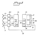
- Figure 5 shows a diagrammatic example of a receiver which can be incorporated in the rotating body.
- The arrangement shown in Figure 1 comprises a launching device 1 shown diagrammatically as a gun barrel and can, for example, consist of a gun. In association with the launching device there is incorporated in the arrangement according to the invention a
transmitter 2 with antenna 3. Thetransmitter 2 with antenna 3 is suitably incorporated in an existing radar in the launching unit, for example a millimetre wave radar. The antenna 3 and the launching device 1 are arranged in a suitable known way to be able to be turned vertically and horizontally. The launchable body is designated 4 and its rear part is provided with areceiver antenna 5. Theantenna 5 is a so-called electrically controlled antenna and is constructed in the rear end of the launchable body 4. The antenna can advantageously consist of antenna slots milled out of metal, a so-called slot antenna, in which the metal can at the same time form part of the casing of the launchable body. By this means the launchable body is given a strong rear end. The electronic components are small and light and thus resistant to G-forces. The arrangement and in particular the antennas are designed preferably for the millimetre wave range and for example to work within the frequency range 35-45 GHz. The advantage of this frequency range is that the antenna can be made very small as the dipoles incorporated in it are only a few millimetres long. This frequency range also functions well in various kinds of weather conditions. - In the embodiment shown the beam of the antenna 3 designated by 6 sweeps horizontally with a suitable sweep angle from for example left to right, an
arrow 7 indicating the return sweep. During the return sweep from right to left the transmitter/radar is kept turned off. The polarization direction of the E-field is shown by anarrow 8. - The
antenna 5 in the launchable body forms abeam 9 which by electrical means sweeps from left to right with reference to thepolarization direction 10 of the E-field. Anarrow 11 indicates the return sweep and the signal during the return sweep is ignored. - The interaction between transmitter sweep and receiver sweep is illustrated in Figure 2a and Figure 2b. A
dotted line 15 marks the centre line of the sweep, whilesolid lines designation 12 refers to the transmitter sweep and thedesignation 13 refers to the receiver sweep. During the second half the beams sweep towards each other, which is shown in Figure 2b. Adotted area 14 indicates where the transmitter and receiver beams coincide. From the diagram it can be seen that the beams coincide for a longer consecutive time when the beams sweep with each other than when the beams sweep towards each other, that is T0 > T1. The receiver can thus detect signals for a longer time for each period of coincidence of the beams when the launchable body rotates within one half revolution than within the other. It is thus possible to determine easily which half of the revolution is concerned. From the diagrams in Figures 2a and 2b it can also be seen that in the illustrated example the receiver sweep has been allocated a shorter sweep time than the transmitter sweep. - At the moment of launching the receiver's sweep is synchronized with the transmitter's by the sweep in the receiver being zeroed. This is shown diagrammatically in Figure 3. The time interval T2 between the sweeps' interceptions is measured and based on the time interval information the sweep in the receiver is started so that it intercepts the transmitter's sweep at approximately 0 degrees.
- Figure 4a shows an example of a signal received in the launchable body via the
antenna 5 and anenvelope curve 18 for this. The signal consists of bursts 19.1 - 19.m, 20.1 - 20.n separated byintervals 21 of just noise. The envelope curve's correspondences in angle are shown in Figure 4b passing through zero at multiples of π. An example of how the receiver can be constructed diagrammatically is described in greater detail below with reference to Figure 5. From Figures 4a and 4b it can be seen that during an interval from 0 to π the received signal increases in strength up to π/2 and then drops towards zero. The peak value corresponds to when the receiver beam's E-field coincides with the direction of the transmitter beam's E-field. This situation is shown in Figure 1 and the E-field is here vertically oriented. At 0 and n radians the launchable body is in such a rotational position that the receiver beam's E-field is oriented at right angles to the transmitter beam's E-field and as a result no signal is obtained. During a second interval from π to 2π there is a corresponding increase and reduction in the signal strength. During the first interval, 0 - π radians, the bursts 19.1 - 19.m have duration T1 while the bursts 20.1 - 20.n during the second interval, π - 2π radians, have duration T0. The difference in duration between T0 and T1 is due to the receiver sweep and the transmitter sweep moving with each other or towards each other and has already been discussed above. A way of determining the angle of roll within an interval 0 - π is to record the envelope for the bursts of the received signal as a function of the angle. As thepoints 0, π, 2π, 3π, etc., are known and the launchable body can be assumed to rotate at an essentially even speed of rotation, the signal value can easily be determined for intermediate angles. Signal values with associated angle values can be stored in a table. The angle of roll within an interval can then be determined by reading off the angle for a particular burst value from the table. - The
receiver 22 shown in Figure 5 is connected on the input side to the electricallycontrollable antenna 9 in the form of a group antenna with a number of controllable antenna elements 9.1 - 9.n. Signals received on the antenna are passed to electrically controllable phase shifters 23.1 - 23.n before being passed to a summation point withenvelope detector 24, which in turn is connected to a digital andcentral processor unit 25 with an A/D transducer 26 on the input side. Signal processing is carried out in theprocessor unit 25 in accordance with the principles outlined above based on incoming information. For this purpose theprocessor unit 25 contains among other things software for measuringamplitude 27 and software for measuringpulse length 28 and provides digital angle of roll information at itsoutput 29. Ablock 30 designates the software which is incorporated in theprocessor unit 25 for controlling the beams of thegroup antenna 9 via anoutput 31. - The invention is not restricted to the described embodiment, but there can be many alternative embodiments within the scope of the invention defined by the patent claims. This applies among other things to the design of the receiver for determining the angle of roll.
Claims (13)
- Method for determining the angle of roll of a launchable body which rotates in its path, such as a rotating projectile, shell, guided missile or the like, which is launched from a launching device (1), in which a transmitter (2) with antenna (3) arranged in connection with the launching device communicates with a receiver (22) with antenna (5) arranged in the launchable body (4), characterized in that the transmitter antenna (3) and receiver antenna (5) are designed with their sweeping beams (6, 9) directed essentially towards each other, in that the transmitter antenna's beam sweeps in a fixed plane relative to the launching device, in that the receiver antenna's beam sweeps in a fixed plane relative to the launchable body, in that the time the two beams coincide is detected and in that the signal strength during the time the beams coincide is recorded to create an imaginary rotation envelope and in that the angle of roll is determined based on the measured times and the created imaginary rotation envelope.
- Method according to Claim 1, characterized in that the difference in the time the sweeping beams (6, 9) coincide depending upon whether the beams sweep with each other or towards each other is used to determine unambiguously the angle of roll for the interval 0 - π or the interval π - 2π.
- Method according to either of the preceding claims, characterized in that the angle of roll within an angle interval 0 - π is determined by the angle corresponding to a position on the rotational envelope.
- Method according to any of the preceding claims, characterized in that the time is measured between two passes of the rotational envelope through zero and in that a specific angle position between two passes through zero is determined by determining the proportion of the time up to the specific angle position of the time between two passes through zero and working out the corresponding proportion of π.
- Method according to any of the preceding claims, characterized in that the transmitter antennas (3) and receiver antennas (5) are dimensioned to work within the millimetre wave range, preferably within the frequency range 35-45 GHz.
- Method according to any of the preceding claims, characterized in that the transmitter antenna's sweeping beam (6) sweeps in the horizontal plane in one direction and is turned off for measurement during the subsequent return sweep and in that the receiver antenna (5) sweeps in one direction and is turned off during the return sweep.
- Method according to any of the preceding claims, characterized in that the receiver antenna's sweeping beam (9) has a shorter sweep time than the transmitter antenna's sweeping beam (6).
- Method according to any of the preceding claims, characterized in that the receiver antenna's sweeping beam (9) is kept zeroed during the moment of launching and
in that the time interval between the transmitter antenna's (3) interceptions with the receiver antenna's zeroed beam is measured and in that after the abovementioned measuring and based on the measurement results the receiver antenna's sweep is started so that it intercepts the transmitter's sweep (7) at approximately 0 degrees. - Method according to any of the preceding claims, characterized in that the transmitter antenna (3) and receiver antenna (5) are allocated sweep ranges of the order of ± 5 degrees.
- Arrangement for determining the angle of roll of a launchable body (4) which rotates in its path, such as a rotating projectile, shell, guided missile or the like, which is launched from a launching device (1), comprising a transmitter (2) with antenna (3) arranged in connection with the launching device (1) and a receiver (22) with antenna (5) arranged in the launchable body (4), characterized in that transmitter antenna (3) and the receiver antenna (5) are designed with sweeping beams (6, 9) and in that the receiver (22) comprises devices (24, 25) for processing received signal information concerning time and signal strength during the time the sweeping beams coincide.
- Arrangement according to Claim 10, characterized
in that an envelope detector is arranged in the receiver (22) to create an imaginary rotational envelope based on the recorded signal strengths during the time the beams coincide. - Arrangement according to either of Claims 10 or 11, characterized in that the receiver (22) comprises a time measuring circuit.
- Arrangement according to any of Claims 10-12, characterized in that the receiver antenna (5) is constructed of electrically controllable antenna elements in the form of dipole slots.
Applications Claiming Priority (3)
| Application Number | Priority Date | Filing Date | Title |
|---|---|---|---|
| SE9903779A SE515386C2 (en) | 1999-10-20 | 1999-10-20 | Method and apparatus for determining the roll angle of an extendable rotating body rotating in its path |
| SE9903779 | 1999-10-20 | ||
| PCT/SE2000/002010 WO2001029505A1 (en) | 1999-10-20 | 2000-10-18 | Method and arrangement for determining the angle of roll of a launchable rotating body which rotates in its path |
Publications (2)
| Publication Number | Publication Date |
|---|---|
| EP1224435A1 EP1224435A1 (en) | 2002-07-24 |
| EP1224435B1 true EP1224435B1 (en) | 2007-03-28 |
Family
ID=20417419
Family Applications (1)
| Application Number | Title | Priority Date | Filing Date |
|---|---|---|---|
| EP00973303A Expired - Lifetime EP1224435B1 (en) | 1999-10-20 | 2000-10-18 | Method and arrangement for determining the angle of roll of a launchable rotating body which rotates in its path |
Country Status (8)
| Country | Link |
|---|---|
| US (1) | US6727843B1 (en) |
| EP (1) | EP1224435B1 (en) |
| AT (1) | ATE358268T1 (en) |
| DE (1) | DE60034137T2 (en) |
| IL (1) | IL149181A (en) |
| SE (1) | SE515386C2 (en) |
| WO (1) | WO2001029505A1 (en) |
| ZA (1) | ZA200203043B (en) |
Families Citing this family (18)
| Publication number | Priority date | Publication date | Assignee | Title |
|---|---|---|---|---|
| US7079070B2 (en) * | 2001-04-16 | 2006-07-18 | Alliant Techsystems Inc. | Radar-filtered projectile |
| SE527769C2 (en) * | 2004-10-28 | 2006-05-30 | Bofors Defence Ab | Method and apparatus for determining roll angle |
| US7589663B1 (en) * | 2006-01-20 | 2009-09-15 | The United States Of America As Represented By The Secretary Of The Army | System and method for the measurement of the unambiguous roll angle of a projectile |
| US8076621B2 (en) * | 2008-09-06 | 2011-12-13 | Omnitek Partners Llc | Integrated reference source and target designator system for high-precision guidance of guided munitions |
| US8258999B2 (en) * | 2009-03-02 | 2012-09-04 | Omnitek Partners Llc | System and method for roll angle indication and measurement in flying objects |
| FR2979995B1 (en) * | 2011-09-09 | 2013-10-11 | Thales Sa | SYSTEM FOR LOCATING A FLYING DEVICE |
| US9683814B2 (en) * | 2015-03-16 | 2017-06-20 | Raytheon Company | Multi-function radio frequency (MFRF) module and gun-launched munition with active and semi-active terminal guidance and fuzing sensors |
| DE102016005910B4 (en) * | 2016-05-17 | 2024-02-15 | Rheinmetall Air Defence Ag | Antenna arrangement of a guided missile with a radar antenna |
| DE102016005912A1 (en) * | 2016-05-17 | 2017-11-23 | Rheinmetall Air Defence Ag | Antenna arrangement of a guided missile with several radar antennas |
| IL248966B2 (en) * | 2016-11-14 | 2023-02-01 | Elta Systems Ltd | Methods and systems for detecting and/or tracking projectile |
| US10948293B2 (en) * | 2017-05-23 | 2021-03-16 | Omnitek Partners Llc | Polarized radio frequency (RF) roll, pitch and yaw angle sensors and orientation misalignment sensors |
| US11555679B1 (en) | 2017-07-07 | 2023-01-17 | Northrop Grumman Systems Corporation | Active spin control |
| US12031802B2 (en) | 2017-07-26 | 2024-07-09 | Northrop Grumman Systems Corporation | Despun wing control system for guided projectile maneuvers |
| US11578956B1 (en) | 2017-11-01 | 2023-02-14 | Northrop Grumman Systems Corporation | Detecting body spin on a projectile |
| US10962990B2 (en) * | 2019-08-07 | 2021-03-30 | Bae Systems Information And Electronic Systems Integration Inc. | Attitude determination by pulse beacon and low cost inertial measuring unit |
| US11573069B1 (en) | 2020-07-02 | 2023-02-07 | Northrop Grumman Systems Corporation | Axial flux machine for use with projectiles |
| SE547385C2 (en) * | 2021-12-14 | 2025-07-29 | Bae Systems Bofors Ab | PROJECTILE WITH ANTENNA AND ANTENNA PROTECTION |
| US12313389B1 (en) | 2022-03-11 | 2025-05-27 | Northrop Grumman Systems Corporation | Tunable safe and arming devices and methods of manufacture |
Family Cites Families (9)
| Publication number | Priority date | Publication date | Assignee | Title |
|---|---|---|---|---|
| US4347996A (en) * | 1980-05-22 | 1982-09-07 | Raytheon Company | Spin-stabilized projectile and guidance system therefor |
| GB2301724B (en) | 1985-11-14 | 1997-08-27 | Gec Marconi Avionics Holdings | Missile roll position determination |
| NL8600710A (en) * | 1986-03-20 | 1987-10-16 | Hollandse Signaalapparaten Bv | DEVICE FOR DETERMINING THE ROTATION POSITION OF AN OBJECT ROTATING ON AN AXIS. |
| NL8900117A (en) | 1988-05-09 | 1989-12-01 | Hollandse Signaalapparaten Bv | SYSTEM FOR DETERMINING THE ROTATION POSITION OF AN ARTICLE ROTATABLE ON AN AXLE. |
| SE465439B (en) | 1990-04-18 | 1991-09-09 | Bofors Ab | DEVICE FOR DETERMINING THE ROLLING ANGLE LOCATION OF A ROTATING PROJECTILE |
| SE468726B (en) | 1991-07-02 | 1993-03-08 | Bofors Ab | DEVICE FOR ROLL ANGLE DETERMINATION |
| US5425514A (en) * | 1993-12-29 | 1995-06-20 | Raytheon Company | Modular aerodynamic gyrodynamic intelligent controlled projectile and method of operating same |
| DE4416210C2 (en) * | 1994-05-07 | 1997-05-22 | Rheinmetall Ind Ag | Method and device for determining the roll angle position of a rotating missile |
| FR2802652B1 (en) * | 1999-12-15 | 2002-03-22 | Thomson Csf | NON-AMBIGUOUS MEASUREMENT OF A PROJECTILE'S ROLL, AND APPLICATION TO THE CORRECTION OF A PROJECTILE |
-
1999
- 1999-10-20 SE SE9903779A patent/SE515386C2/en not_active IP Right Cessation
-
2000
- 2000-10-18 EP EP00973303A patent/EP1224435B1/en not_active Expired - Lifetime
- 2000-10-18 US US10/111,165 patent/US6727843B1/en not_active Expired - Fee Related
- 2000-10-18 WO PCT/SE2000/002010 patent/WO2001029505A1/en not_active Ceased
- 2000-10-18 DE DE60034137T patent/DE60034137T2/en not_active Expired - Fee Related
- 2000-10-18 IL IL14918100A patent/IL149181A/en not_active IP Right Cessation
- 2000-10-18 AT AT00973303T patent/ATE358268T1/en not_active IP Right Cessation
-
2002
- 2002-04-17 ZA ZA200203043A patent/ZA200203043B/en unknown
Also Published As
| Publication number | Publication date |
|---|---|
| DE60034137T2 (en) | 2007-12-06 |
| WO2001029505A1 (en) | 2001-04-26 |
| SE9903779D0 (en) | 1999-10-20 |
| SE515386C2 (en) | 2001-07-23 |
| ZA200203043B (en) | 2003-04-17 |
| IL149181A (en) | 2005-08-31 |
| SE9903779L (en) | 2001-04-21 |
| EP1224435A1 (en) | 2002-07-24 |
| ATE358268T1 (en) | 2007-04-15 |
| IL149181A0 (en) | 2002-11-10 |
| US6727843B1 (en) | 2004-04-27 |
| DE60034137D1 (en) | 2007-05-10 |
Similar Documents
| Publication | Publication Date | Title |
|---|---|---|
| US6727843B1 (en) | Method and arrangement for determining the angle of roll of a launchable rotating body which rotates in its paths | |
| JP2575651B2 (en) | Radar device | |
| US4184154A (en) | Range and angle determining Doppler radar | |
| US4952939A (en) | Radar intrusion detection system | |
| US4107680A (en) | Digitally processed radar speed sensor | |
| TW200521469A (en) | Multiple radar combining for increased range, radar sensitivity and angle accuracy | |
| JP2828336B2 (en) | Doppler radar for helicopter detection and position measurement. | |
| WO2012052856A1 (en) | Floodlight radar system for detecting and locating moving targets in three dimensions | |
| WO2003038462A2 (en) | Spread spectrum radar with leak compensation at baseband | |
| US20180267140A1 (en) | High spatial resolution 3d radar based on a single sensor | |
| Sturm et al. | Automotive fast-chirp MIMO radar with simultaneous transmission in a Doppler-multiplex | |
| CA2010959A1 (en) | Ranging Systems | |
| JPS6238668B2 (en) | ||
| NO176982B (en) | Device for determining the rolling angle of a rotating projectile or the like. | |
| US4072944A (en) | Imminent collision detection apparatus | |
| WO1986000998A1 (en) | Antenna tracking system using sequential lobing | |
| US3246322A (en) | Distance measuring equipment | |
| JP3160292B2 (en) | Radar equipment | |
| US4306500A (en) | Optical backscatter reduction technique | |
| RU2115139C1 (en) | Device measuring range | |
| US3171125A (en) | Radar countermeasures antenna system | |
| RU2206903C2 (en) | Radar for helicopter | |
| US3859658A (en) | Conical scan tracking system | |
| GB2059214A (en) | Range and angle determining Doppler radar | |
| US4250506A (en) | Sidelobe discriminator |
Legal Events
| Date | Code | Title | Description |
|---|---|---|---|
| PUAI | Public reference made under article 153(3) epc to a published international application that has entered the european phase |
Free format text: ORIGINAL CODE: 0009012 |
|
| 17P | Request for examination filed |
Effective date: 20020515 |
|
| AK | Designated contracting states |
Kind code of ref document: A1 Designated state(s): AT BE CH CY DE DK ES FI FR GB GR IE IT LI LU MC NL PT SE |
|
| AX | Request for extension of the european patent |
Free format text: AL;LT;LV;MK;RO;SI |
|
| GRAP | Despatch of communication of intention to grant a patent |
Free format text: ORIGINAL CODE: EPIDOSNIGR1 |
|
| RIC1 | Information provided on ipc code assigned before grant |
Ipc: F41G 7/30 20060101AFI20061004BHEP |
|
| RAP1 | Party data changed (applicant data changed or rights of an application transferred) |
Owner name: BAE SYSTEMS BOFORS AB |
|
| GRAS | Grant fee paid |
Free format text: ORIGINAL CODE: EPIDOSNIGR3 |
|
| GRAA | (expected) grant |
Free format text: ORIGINAL CODE: 0009210 |
|
| AK | Designated contracting states |
Kind code of ref document: B1 Designated state(s): AT BE CH CY DE DK ES FI FR GB GR IE IT LI LU MC NL PT SE |
|
| PG25 | Lapsed in a contracting state [announced via postgrant information from national office to epo] |
Ref country code: AT Free format text: LAPSE BECAUSE OF FAILURE TO SUBMIT A TRANSLATION OF THE DESCRIPTION OR TO PAY THE FEE WITHIN THE PRESCRIBED TIME-LIMIT Effective date: 20070328 Ref country code: NL Free format text: LAPSE BECAUSE OF FAILURE TO SUBMIT A TRANSLATION OF THE DESCRIPTION OR TO PAY THE FEE WITHIN THE PRESCRIBED TIME-LIMIT Effective date: 20070328 Ref country code: FI Free format text: LAPSE BECAUSE OF FAILURE TO SUBMIT A TRANSLATION OF THE DESCRIPTION OR TO PAY THE FEE WITHIN THE PRESCRIBED TIME-LIMIT Effective date: 20070328 Ref country code: BE Free format text: LAPSE BECAUSE OF FAILURE TO SUBMIT A TRANSLATION OF THE DESCRIPTION OR TO PAY THE FEE WITHIN THE PRESCRIBED TIME-LIMIT Effective date: 20070328 Ref country code: CH Free format text: LAPSE BECAUSE OF FAILURE TO SUBMIT A TRANSLATION OF THE DESCRIPTION OR TO PAY THE FEE WITHIN THE PRESCRIBED TIME-LIMIT Effective date: 20070328 Ref country code: LI Free format text: LAPSE BECAUSE OF FAILURE TO SUBMIT A TRANSLATION OF THE DESCRIPTION OR TO PAY THE FEE WITHIN THE PRESCRIBED TIME-LIMIT Effective date: 20070328 |
|
| REG | Reference to a national code |
Ref country code: GB Ref legal event code: FG4D |
|
| REG | Reference to a national code |
Ref country code: CH Ref legal event code: EP |
|
| REF | Corresponds to: |
Ref document number: 60034137 Country of ref document: DE Date of ref document: 20070510 Kind code of ref document: P |
|
| REG | Reference to a national code |
Ref country code: IE Ref legal event code: FG4D |
|
| PG25 | Lapsed in a contracting state [announced via postgrant information from national office to epo] |
Ref country code: SE Free format text: LAPSE BECAUSE OF FAILURE TO SUBMIT A TRANSLATION OF THE DESCRIPTION OR TO PAY THE FEE WITHIN THE PRESCRIBED TIME-LIMIT Effective date: 20070628 |
|
| PG25 | Lapsed in a contracting state [announced via postgrant information from national office to epo] |
Ref country code: ES Free format text: LAPSE BECAUSE OF FAILURE TO SUBMIT A TRANSLATION OF THE DESCRIPTION OR TO PAY THE FEE WITHIN THE PRESCRIBED TIME-LIMIT Effective date: 20070709 |
|
| ET | Fr: translation filed | ||
| PG25 | Lapsed in a contracting state [announced via postgrant information from national office to epo] |
Ref country code: PT Free format text: LAPSE BECAUSE OF FAILURE TO SUBMIT A TRANSLATION OF THE DESCRIPTION OR TO PAY THE FEE WITHIN THE PRESCRIBED TIME-LIMIT Effective date: 20070828 |
|
| REG | Reference to a national code |
Ref country code: CH Ref legal event code: PL |
|
| NLV1 | Nl: lapsed or annulled due to failure to fulfill the requirements of art. 29p and 29m of the patents act | ||
| PG25 | Lapsed in a contracting state [announced via postgrant information from national office to epo] |
Ref country code: DK Free format text: LAPSE BECAUSE OF FAILURE TO SUBMIT A TRANSLATION OF THE DESCRIPTION OR TO PAY THE FEE WITHIN THE PRESCRIBED TIME-LIMIT Effective date: 20070328 |
|
| PLBE | No opposition filed within time limit |
Free format text: ORIGINAL CODE: 0009261 |
|
| STAA | Information on the status of an ep patent application or granted ep patent |
Free format text: STATUS: NO OPPOSITION FILED WITHIN TIME LIMIT |
|
| 26N | No opposition filed |
Effective date: 20080102 |
|
| PG25 | Lapsed in a contracting state [announced via postgrant information from national office to epo] |
Ref country code: GR Free format text: LAPSE BECAUSE OF FAILURE TO SUBMIT A TRANSLATION OF THE DESCRIPTION OR TO PAY THE FEE WITHIN THE PRESCRIBED TIME-LIMIT Effective date: 20070629 |
|
| PG25 | Lapsed in a contracting state [announced via postgrant information from national office to epo] |
Ref country code: MC Free format text: LAPSE BECAUSE OF NON-PAYMENT OF DUE FEES Effective date: 20071031 |
|
| PG25 | Lapsed in a contracting state [announced via postgrant information from national office to epo] |
Ref country code: IE Free format text: LAPSE BECAUSE OF NON-PAYMENT OF DUE FEES Effective date: 20071018 |
|
| PGFP | Annual fee paid to national office [announced via postgrant information from national office to epo] |
Ref country code: IT Payment date: 20080923 Year of fee payment: 9 |
|
| PGFP | Annual fee paid to national office [announced via postgrant information from national office to epo] |
Ref country code: FR Payment date: 20081016 Year of fee payment: 9 |
|
| PGFP | Annual fee paid to national office [announced via postgrant information from national office to epo] |
Ref country code: DE Payment date: 20081219 Year of fee payment: 9 |
|
| PGFP | Annual fee paid to national office [announced via postgrant information from national office to epo] |
Ref country code: GB Payment date: 20081015 Year of fee payment: 9 |
|
| PG25 | Lapsed in a contracting state [announced via postgrant information from national office to epo] |
Ref country code: CY Free format text: LAPSE BECAUSE OF FAILURE TO SUBMIT A TRANSLATION OF THE DESCRIPTION OR TO PAY THE FEE WITHIN THE PRESCRIBED TIME-LIMIT Effective date: 20070328 |
|
| PG25 | Lapsed in a contracting state [announced via postgrant information from national office to epo] |
Ref country code: LU Free format text: LAPSE BECAUSE OF NON-PAYMENT OF DUE FEES Effective date: 20071018 |
|
| REG | Reference to a national code |
Ref country code: FR Ref legal event code: ST Effective date: 20100630 |
|
| PG25 | Lapsed in a contracting state [announced via postgrant information from national office to epo] |
Ref country code: DE Free format text: LAPSE BECAUSE OF NON-PAYMENT OF DUE FEES Effective date: 20100501 Ref country code: FR Free format text: LAPSE BECAUSE OF NON-PAYMENT OF DUE FEES Effective date: 20091102 |
|
| PG25 | Lapsed in a contracting state [announced via postgrant information from national office to epo] |
Ref country code: GB Free format text: LAPSE BECAUSE OF NON-PAYMENT OF DUE FEES Effective date: 20091018 |
|
| PG25 | Lapsed in a contracting state [announced via postgrant information from national office to epo] |
Ref country code: IT Free format text: LAPSE BECAUSE OF NON-PAYMENT OF DUE FEES Effective date: 20091018 |