EP1224099B1 - Load floor latch - Google Patents
Load floor latch Download PDFInfo
- Publication number
- EP1224099B1 EP1224099B1 EP00908772A EP00908772A EP1224099B1 EP 1224099 B1 EP1224099 B1 EP 1224099B1 EP 00908772 A EP00908772 A EP 00908772A EP 00908772 A EP00908772 A EP 00908772A EP 1224099 B1 EP1224099 B1 EP 1224099B1
- Authority
- EP
- European Patent Office
- Prior art keywords
- handle
- latch
- housing
- pawl
- actuator
- Prior art date
- Legal status (The legal status is an assumption and is not a legal conclusion. Google has not performed a legal analysis and makes no representation as to the accuracy of the status listed.)
- Expired - Lifetime
Links
- 230000004044 response Effects 0.000 claims description 4
- 230000007246 mechanism Effects 0.000 abstract description 15
- 230000004913 activation Effects 0.000 description 2
- 238000010276 construction Methods 0.000 description 2
- 230000014759 maintenance of location Effects 0.000 description 2
- 230000013011 mating Effects 0.000 description 2
- 230000004048 modification Effects 0.000 description 2
- 238000012986 modification Methods 0.000 description 2
- 206010039203 Road traffic accident Diseases 0.000 description 1
- 230000008859 change Effects 0.000 description 1
- 239000004035 construction material Substances 0.000 description 1
- 230000000994 depressogenic effect Effects 0.000 description 1
- 230000006872 improvement Effects 0.000 description 1
- 238000009434 installation Methods 0.000 description 1
- 230000003993 interaction Effects 0.000 description 1
- 239000000463 material Substances 0.000 description 1
- 230000001105 regulatory effect Effects 0.000 description 1
- 230000000087 stabilizing effect Effects 0.000 description 1
- 238000005728 strengthening Methods 0.000 description 1
Images










Classifications
-
- E—FIXED CONSTRUCTIONS
- E05—LOCKS; KEYS; WINDOW OR DOOR FITTINGS; SAFES
- E05B—LOCKS; ACCESSORIES THEREFOR; HANDCUFFS
- E05B13/00—Devices preventing the key or the handle or both from being used
- E05B13/10—Devices preventing the key or the handle or both from being used formed by a lock arranged in the handle
-
- E—FIXED CONSTRUCTIONS
- E05—LOCKS; KEYS; WINDOW OR DOOR FITTINGS; SAFES
- E05B—LOCKS; ACCESSORIES THEREFOR; HANDCUFFS
- E05B13/00—Devices preventing the key or the handle or both from being used
- E05B13/002—Devices preventing the key or the handle or both from being used locking the handle
-
- E—FIXED CONSTRUCTIONS
- E05—LOCKS; KEYS; WINDOW OR DOOR FITTINGS; SAFES
- E05C—BOLTS OR FASTENING DEVICES FOR WINGS, SPECIALLY FOR DOORS OR WINDOWS
- E05C1/00—Fastening devices with bolts moving rectilinearly
- E05C1/08—Fastening devices with bolts moving rectilinearly with latching action
- E05C1/12—Fastening devices with bolts moving rectilinearly with latching action with operating handle or equivalent member moving otherwise than rigidly with the latch
- E05C1/14—Fastening devices with bolts moving rectilinearly with latching action with operating handle or equivalent member moving otherwise than rigidly with the latch the handle or member moving essentially towards or away from the plane of the wing or frame
- E05C1/145—Fastening devices with bolts moving rectilinearly with latching action with operating handle or equivalent member moving otherwise than rigidly with the latch the handle or member moving essentially towards or away from the plane of the wing or frame flush
-
- E—FIXED CONSTRUCTIONS
- E05—LOCKS; KEYS; WINDOW OR DOOR FITTINGS; SAFES
- E05C—BOLTS OR FASTENING DEVICES FOR WINGS, SPECIALLY FOR DOORS OR WINDOWS
- E05C19/00—Other devices specially designed for securing wings, e.g. with suction cups
- E05C19/06—Other devices specially designed for securing wings, e.g. with suction cups in which the securing part if formed or carried by a spring and moves only by distortion of the spring, e.g. snaps
-
- E—FIXED CONSTRUCTIONS
- E05—LOCKS; KEYS; WINDOW OR DOOR FITTINGS; SAFES
- E05B—LOCKS; ACCESSORIES THEREFOR; HANDCUFFS
- E05B15/00—Other details of locks; Parts for engagement by bolts of fastening devices
- E05B15/04—Spring arrangements in locks
- E05B2015/0468—Spring arrangements in locks made of one piece with a lock part
Definitions
- the present invention relates to the field of latches and more particularly to slam-action latches in which a handle is lifted to release the latch pawl from engagement with a keeper.
- Slam-action latches are known in the art and are employed in a number of applications for securing one or more panels together.
- latches coming within this category operate by forcing a pawl into engagement with a keeper.
- a first panel member has a pawl mounted on it and a second panel member, such as, for example, a cabinet, has a keeper mounted thereon, slamming shut the first panel member against the second panel member can secure the panels with the latch.
- separately provided spring members are utilized to bias the pawl into engagement with a keeper member.
- the pawl engages a keeper.
- the utilization of a separately provided spring member often increases the cost of the latch and the time for assembly or construction of the latch.
- complex mechanisms are required to maintain spring members and align them with a pawl saw the pawl can be regulated to operate and engage and disengage a keeper.
- US patent 2,186,903 discloses a door latch, which comprises a pivotally movable handle 9,10 with two finger type extensions 14, which are adapted to slide along two oblique surfaces 32 on an extension of a pawl base 25.
- the pawl also comprises two bolts 26, by which the pawl is guided.
- the handle is pivotally mounted in a latch housing 1, whereas for the pawl a separate housing 17 is provided.
- US patent 4,312,202 discloses a door lock, comprising a pivotally movable handle 138, acting on a bolt 90.
- a part 180 of the bolt 90 which is pivotally connected to the bolt 90 at a junction 224, and which comprises a contact surface 204 to an extension 142 of the handle 138, can be pivoted by a key control 150, in order to disengage the extension 142 of the handle 138 from the connection surface 204 of the bolt 90 when the handle 138 is pivoted in the opening position.
- the US patent 3,782,141 discloses a door latch comprising a pivotally movable handle 54 and a lock bolt 44.
- the lock bolt 44 is moved by an extension 66 of the handle 54. In this operation, the edge of the extension 66 scratches over an inner surface of the lock bolt 44, making the mechanism highly prone to wear.
- a door lock comprising a pivotally movable handle 14 and a bolt 12 is described.
- the handle 14 has an extension 43, which contacts and moves the bolt 12 at a contact location 41 when pivoting the handle.
- a small edge of the extension 43 of the handle 14 scratches over a corresponding inner surface of the bolt 12, leading to high wear during operation.
- load floor latches are commonly used in the automotive industry. Often, these latches are employed to secure the contents of a compartment in a cargo area.
- load floor latches find use for securing a floor panel, such as the panel which regulates access to vehicle items, such as spare tires, tools, jacks, batteries, and the like.
- the floor panel is provided on the floor of the vehicle passenger or cargo compartment.
- the latch therefore must be durable, and it is desirable that the latch withstands substantial force loads, such as those of the type generally encountered by bumps, rough terrain, and especially vehicular accidents, such as crashes, or rollover situations. It is important that compartment contents remain secured in the event of a vehicle crash or rollover.
- the pawl member is preferably spring biased and is retracted inwardly, within the housing.
- the pawl member is slidably carried in the housing and extends therefrom.
- the handle is pivotally connected to the housing and pivots relative thereto.
- Locking mechanism preferably can be provided for securing the actuator against movement to prevent unauthorised activation.
- the locking mechanism can be applied to compartment contents would spill out Into the passenger compartment, thereby placing the vehicle operator in danger.
- a need exists for a load floor latch which has improved abilities to withstand a rollover, and facilitate latching of a panel, even under high stress conditions. It is also important that the latch, in addition to being durable, be easy to construct and install. Furthermore, a need exists for a mechanism that is durable, provides a rigid construction and allows for the use of low strengths materials.
- the present invention provides a novel slam latch having a handle, a housing and a pawl member which is disposed to engage a keeper member to secure a first member, such as a door or floor panel, to a second member, such as a frame or floor.
- the latch can be installed on a closure panel and a keeper member on another panel or frame.
- the latch for example, may be installed on a vehicle floor panel and a keeper can be installed on a corresponding frame.
- the latch handle upon being actuated, by lifting, operates to reject the pawl from engagement with a keeper member.
- an actuator is provided which extends through the housing and connects with the pawl. The handle, by contacting the actuator withdraws the pawl member out from engagement with the keeper to release the latch and permit the closure panel to be opened.
- a latch for securing a first member to a second member
- said latch comprising: a housing which is adapted for mounting to the first member, a pawl member slidably supported by said housing said pawl member being movable between extended and retracted positions, and said pawl member being adapted to secure the first member relative to the second member when said pawl member is in said extended position and the first member is in a closed position relative to the second member, said pawl member having a plurality of slots; a handle pivotally supported by said housing and being moveable over a pivot range Including open and closed positions, and an actuator for engaging said pawl member and at least moving said pawl member from said extended position toward said retracted position in response to pivotal movement of said handle from said closed position toward said open position, said actuator being slidably supported by said housing such that said actuator moves rearwardly relative to said housing in response to said handle moving toward said open position, characterised in that said actuator includes a base and a plurality
- the pawl member is preferably spring biased and is retracted inwardly, within the housing.
- the pawl member is slidably carried in the housing and extends therefrom.
- the handle is pivotally connected to the housing and pivots relative thereto.
- Locking mechanism preferably can be provided for securing the actuator against movement to prevent unauthorised activation.
- the locking mechanism can be applied to allow the latch to be locked to prevent the pawl from being released from a keeper member.
- the latch further has an improved stabilizing mechanism which facilitates retention of the latch in a latching position during vehicle crashes and rollovers.
- An object of the present invention is to provide a novel latch which can secure one or more members together, such as panels or the like, for selective release by actuating a handle of the latch.
- Another object of the present invention is to accomplish the above objects by providing a spring-biased latch which can be closed by slam-action.
- Another object of the present invention is to provide a novel latch which can be closed by slam-action, even when the latch handle is in the closed position, and when the latch is not connected to a keeper.
- Another object of the present invention is to provide a latch which can be used in connection with panels of vehicles to regulate access to and from an area or compartment, such as, for example, a floor panel and a floor storage compartment.
- Another object of the present invention is to provide a novel latch having a pawl member which is slidably guided for movement within a housing.
- Another object of the present invention is to provide a locking mechanism which can secure the latch against unauthorized opening.
- Another object of the present invention is to provide resistance when the pawl member is being opened or closed with the handle to bias the pawl to an engaging position.
- Another object of the present invention is to provide a latch which has improved retention characteristics under stress forces, such as those experienced by vehicle rollovers and crashes.
- a first alternate embodiment of a latch 10 comprising a latch body or housing 11, a handle 12, a pawl member 13, and an actuator 14.
- Biasing means for biasing the pawl member 13 toward a latching position is shown comprising a spring 15.
- the housing 11 has an upper flange 25 which defines the perimeter of the latch 10.
- Mounting means is provided on the housing 11, and preferably, for example, can comprise posts, such as those 26, which, for example, can have a bore with threads for receiving a matingly threaded bolt (not shown) for attachment of the latch 10 to a panel member (not shown).
- any suitable mounting members such as, rivets, screws, pins, barbs and the like can be used to secure the housing 11 to a panel.
- the latch 10 can be installed on a floor panel of a vehicle to regulate access to and from a compartment.
- Locking means is also provided to lock the latch 10 against unauthorized opening.
- the locking means is shown comprising a lock plug 20 which has a key slot 28 therein.
- the housing 11 has a socket 19 in which the lock plug 20 is installed.
- the locking means further includes a locking element 21, and retaining means for retaining the lock plug 20 on the housing 11.
- the retaining means is shown comprising a retaining member 22 which is disposed on a connecting end 27 of the lockplug 20 located on the lockplug end opposite of the key slot 28 end.
- the retaining member 22 comprises a spring member and is flexible.
- the retaining element 22 secures the lock plug 20 and further is provided to selectively engage the locking element 21, as shown best in Figs. 2 and 3 , to lock the actuator 14 from movement and thereby maintain the pawl member 13 in a latched position.
- the retaining member 22 has an arm 24 which extends outwardly therefrom for engagement with the locking element 21 ( Figs. 2 and 3 ).
- Figs. 2 and 3 show the retaining member 22 installed on the lock plug-connecting end 27.
- the retaining member 22 has an assembly slot 30 for facilitating snap-fit installation onto the lock plug 20.
- Detents 31, 32 are provided on the retaining member 22 for indicating the stop positions of the retaining member 22 when the lock plug is rotated with a key (not shown).
- the retaining member 22 is configured to be rotated by the lock plug 20 with the operation of a key (not shown) inserted and rotated in the key slot 28.
- the handle 12 is shown in a separate view having a body 37 with a lifting portion 40, a pair of flanges 38, 39 on opposite sides of the handle 12, and mounting means for mounting the handle 12 to the housing 11, the mounting means comprising a pair of pivot bosses 41, 42 disposed on the flanges 38, 39, respectively.
- Contact means for contacting the actuator 14 is provided on the front of the handle 12 opposite the lifting portion 40.
- the contact means is shown comprising a tab 43 disposed on the handle body 37.
- the handle 12 further has a recess 49 provided for accommodating the lock plug 20, by permitting the top of the lock plug 20 to reside in the recess 49 when the handle 12 is closed.
- a slot 50 is disposed in the front wall 49 of the housing 11 for receiving the pawl member 13 therein.
- the slot 50 preferably, is matingly configured to accommodate the pawl 13 and facilitate the movement of the pawl member 13 therein.
- the housing slot 50 preferably can be provided with strengthening ribs 51, 52 disposed on opposite sides of the slot 50.
- the slot 50 is shown having a pair of tracks 54, 55, which are provided for mating association with the pawl 13.
- the pawl member 14, as shown in Fig. 7 has surfaces 57,58 which facilitate sliding of the pawl 13 along the tracks 54, 55 of the housing slot 50.
- the housing 11 has a pair of apertures 60,61 each being disposed on opposite sides thereof.
- the pivot bosses 41,42 of the handle 12 are carried in the pivot apertures 60,61, respectively to pivotally maintain the handle 12 on the housing 11.
- the handle 12 has side flanges 38, 39 which facilitate alignment of the handle 12 relative to the housing 11.
- the housing 11 is provided with a first side ledge 64 and a second side ledge 65 disposed on each side thereof.
- the first side ledge 64 provides a seat for the handle side flange 38 when the handle 12 is in its closed ( Fig. 1 ) position.
- the second side ledge 65 provides a seat for the second flange 39 on the opposite handle side.
- the first and second ledges 64,65 are positioned at a height sufficient to raise the handle 12 slightly off of the top of the lock plug 20.
- the lock plug 20 can be utilized to further stabilize the latch handle 12 by providing an additional seat on which the handle 12 may rest. This is accomplished by arranging the flanges and heights of the first and second side ledges to correspond to the height of the lock plug 20.
- the actuator 14 is shown having handle engaging means for engaging with the handle 12.
- the handle engaging means is shown comprising a plurality of contact ribs 70 which are angled to maximize the contact with the handle tab portion 43 when the handle 12 is pivoted to engage the actuator 14.
- the contact ribs 70 are shown supported on a shelf or base 69 of the actuator.
- the actuator 14 further has connecting means for connecting with the pawl member 13 to retract and release the pawl 13.
- the connecting means is shown comprising snap legs 71, 72 which extend downwardly from the actuator shelf or base 69 and are provided with a tapered flange portions 73, 74, respectively, which are shown provided on three sides of each leg 71, 72. Stop means is provided for stopping the locking element 21.
- the stop means is shown comprising a stop leg member 75 extending downwardly from the shelf or base 69 of the actuator 14.
- the stop leg 75 is provided on the outer end of the actuator 14 to facilitate interaction with the locking element 21.
- the actuator stop leg 75 is provided with a widened portion, such as the head 76, disposed facing and in a position for engaging the locking element 21.
- the actuator 14 further comprises supporting means for supporting the actuator 14 in relation to the pawl 13 and housing 11.
- the supporting means are best shown in Fig. 9 comprising supporting legs 77, 78 extending downwardly from the shelf or base 69 of the actuator 14.
- Fig. 10 shows the housing 11 with a floor 80 having a plurality of slots 81, 82, 83, 84, 85 disposed therein.
- the slots 81, 82,83, 84, 85 are provided to correspond, respectively, with the snap legs 71, 72, stop leg 75, and supporting legs 77, 78 to permit them to pass through the housing floor 80 and into the pawl 13.
- the pawl 13 is shown having a plurality of slots 91,92,93,94, 95 disposed therein for accommodating the legs 71,72,75,77,78 of the actuation member 14 which extend into the slots 91,92, 93,94,95, respectively.
- the housing 11 is shown having a pawl slot 50 which is matingly configured to slidably carry the pawl 13 therein.
- the mating configuration of the slot 50 facilitates alignment of the slots 91,92, 93,94,95 with the housing slots 81,82,83,84,85, respectively, to enable the legs of the actuator 14 to extend through the pawl slots.
- the outer slot 85 of the pawl member 13 is partially open on a side thereof.
- the stop leg 75 of the actuator extends through the outer slot 85.
- the locking element 21 is positioned in the outer slot 85 for selective engagement with the retaining member arm 24.
- the locking element 21 is maintained within the pawl slot 50 of the housing 11.
- the pawl slot 50 is defined by the housing floor 80, which defines the top of the slot 50, a rear wall 101, and a bottom wall 102.
- the pawl 13, spring 15, and locking element 21 are held between the floor 80 and the bottom wall 102.
- the pawl 13 is biased with the force of the spring 15 into a forward, engaging position, where the pawl 13 protrudes outwardly from the housing 11. After the pawl 13 has been retracted, the bias from the spring 15 further operates against the pawl 13 to return the pawl to its forward, latching position.
- the pawl 13 is withdrawn by lifting the handle 12, which forces the handle tab 43 into engagement with the contacting ribs 70 of the actuator 14.
- the actuator 14 is then forced rearwardly in the housing 11, with the legs 71, 72, 77 and 78 engaging against the rearward end of each respective pawl slot 91, 92, 94, 95, and the rearward end of the stop leg 75 engaging against the locking element 21.
- the configuration of the present latch 10 allows the pawl 13 to be forced inward into the slot 50 of the housing 11 when encountering a force, such as that from a keeper (not shown). This permits the latch 10 to be slam locked, even when the retaining member 22 is in the locked position.
- the pawl 13 can be depressed inwardly and the locking member 21 will be accommodated by the outer slot 85 of the pawl 13, when the pawl is forced inward.
- the pawl 13 after being forced inward, once it clears a keeper and encounters no further resistance, is biased by the spring 15 toward its outward position, to secure the latch 10.
- detent means for holding the handle 12 in the raised position comprising a resilient engaging element 98, 99 disposed on opposite sides of the housing 11.
- the detent means preferably can maintain the handle 12 in a raised position until the detent force is overcome by lowering the handle 12.
- a second alternate embodiment of a latch 210 is shown.
- the latch 210 is similar to the latch 10 of the first embodiment shown and described herein, but having an alternate locking mechanism and an alternate pawl 213, which is configured having a rectangular cross-section to slide within a space 250 provided in the housing 211.
- the alternate locking mechanism shows locking means comprising a lock plug 222 with a locking pawl arm 224.
- the locking pawl arm 224 is preferably a spring member to permit slam-action closing of the latch 210 in both conditions, when the locking pawl arm 224 is in the latching ( Fig. 12 ) position, and when the locking pawl 224 is rotated to the side, as shown in Fig. 13 , in the open position.
- the spring force furnished with the locking pawl arm 224 enables the locking pawl arm 224 to snap over a keeper (not shown), and into its locking position.
- the handle 212 is lifted and the handle tab 243 engages the actuator 214 to retract the pawl 213 inwardly within the housing slot 250 ( Fig. 15 ).
- a third alternate embodiment of a latch 310 is shown according to the present invention.
- the latch 310 is provided to operate similar to the latch of the second embodiment 210 described above, but without a lock.
- the latch 310 is shown having a housing 311, a handle 312 pivotally connected thereto, a pawl 313 disposed to slide in a slot 350 of the housing 311, an actuator 314, and a spring 315 which biases the pawl 313 toward a latching position, to protrude outwardly from the housing 311.
- the actuator 314 can connect with the pawl 313 through a plurality of slots, such as that 370, shown in Fig. 17 , which are provided on the housing floor 380.
- the handle tab 343 is provided to engage the actuator 314 when the handle 312 is lifted, as shown in Fig. 18 .
- the actuator 314 can comprise the same configuration with the same legs as those described above in connection with the actuator 14 of the first embodiment of the latch 10.
- mounting means is provided on the housing 311, comprising bores, such as that 326 (there being one or more additional bores, not shown).
- a latch embodiment can be employed with another latch embodiment consistent with the principles of the applicant's present invention.
- Other modifications to the above description can be made consistent with the spirit and scope of the invention disclosed herein.
- the keeper is referred to as a separate member, it will be understood that the keeper can comprise a panel, enclosure frame or other surface which the pawl can engage, consistent with the disclosure provided herein.
- a knob, handle or other member can be used to rotate a member into and out of the way of the actuator or secondary keeper such as with the second alternate embodiment) to regulate the opening and closing.
Landscapes
- Engineering & Computer Science (AREA)
- Mechanical Engineering (AREA)
- Lock And Its Accessories (AREA)
- Seats For Vehicles (AREA)
Abstract
Description
- The present invention relates to the field of latches and more particularly to slam-action latches in which a handle is lifted to release the latch pawl from engagement with a keeper.
- Slam-action latches are known in the art and are employed in a number of applications for securing one or more panels together. Generally, latches coming within this category operate by forcing a pawl into engagement with a keeper. For example, where a first panel member has a pawl mounted on it and a second panel member, such as, for example, a cabinet, has a keeper mounted thereon, slamming shut the first panel member against the second panel member can secure the panels with the latch.
- In many instances, separately provided spring members are utilized to bias the pawl into engagement with a keeper member. Thus, when a panel to which the latch is installed is closed, the pawl engages a keeper. The utilization of a separately provided spring member often increases the cost of the latch and the time for assembly or construction of the latch. In some cases, complex mechanisms are required to maintain spring members and align them with a pawl saw the pawl can be regulated to operate and engage and disengage a keeper.
-
US patent 2,186,903 discloses a door latch, which comprises a pivotallymovable handle 9,10 with twofinger type extensions 14, which are adapted to slide along twooblique surfaces 32 on an extension of apawl base 25. The pawl also comprises twobolts 26, by which the pawl is guided. The handle is pivotally mounted in a latch housing 1, whereas for the pawl a separate housing 17 is provided. -
US patent 4,312,202 discloses a door lock, comprising a pivotally movable handle 138, acting on a bolt 90. A part 180 of the bolt 90, which is pivotally connected to the bolt 90 at ajunction 224, and which comprises a contact surface 204 to an extension 142 of the handle 138, can be pivoted by a key control 150, in order to disengage the extension 142 of the handle 138 from the connection surface 204 of the bolt 90 when the handle 138 is pivoted in the opening position. - Subject matter of
US patent 4,683,736 is a cabinet lock with a pivotally movable handle 400, which acts on an operating member 300, which in turn acts on a bolt 200. The bolt 200 is retracted into the housing of the lock by sliding along an oblique surface 356 of the operating member 300. By this mechanism, high wedging forces are executed on the small surface 356 of the operating member 300 as wall as on the corresponding counter-surface of the bolt 200. Also, on the guiding of the bolt 200 in the housing of the lock high forces are exerted. Therefore, in this construction materials of high strength are required in order to achieve a good durability of the mechanism. - The
US patent 3,782,141 discloses a door latch comprising a pivotallymovable handle 54 and a lock bolt 44. The lock bolt 44 is moved by an extension 66 of thehandle 54. In this operation, the edge of the extension 66 scratches over an inner surface of the lock bolt 44, making the mechanism highly prone to wear. - In the
US patent 2,987,908 , a door lock comprising a pivotallymovable handle 14 and abolt 12 is described. Thehandle 14 has anextension 43, which contacts and moves thebolt 12 at acontact location 41 when pivoting the handle. At thecontact location 41, a small edge of theextension 43 of thehandle 14 scratches over a corresponding inner surface of thebolt 12, leading to high wear during operation. - A need exists for a latch which can provide an improvement over the prior art in that it will be less costly to produce and less time-consuming to assemble, as well as providing slam-action latching ability when the latch is detached from a keeper but in the closed position.
- A further need exists for a latch which can be locked, and slammed shut to close and lock the latch, when its pawl is not engaged with a keeper.
- In addition, load floor latches are commonly used in the automotive industry. Often, these latches are employed to secure the contents of a compartment in a cargo area. For examples, load floor latches find use for securing a floor panel, such as the panel which regulates access to vehicle items, such as spare tires, tools, jacks, batteries, and the like. In many cases, the floor panel is provided on the floor of the vehicle passenger or cargo compartment. The latch therefore must be durable, and it is desirable that the latch withstands substantial force loads, such as those of the type generally encountered by bumps, rough terrain, and especially vehicular accidents, such as crashes, or rollover situations. It is important that compartment contents remain secured in the event of a vehicle crash or rollover. This is especially more important where the cargo compartment is located in the same general area as the vehicle operator, or other passengers. For example, in station wagon type vehicles, the cargo space for passengers and items of cargo is the same. Thus, in this type of vehicle, there is great danger to be encountered should rollover of the vehicle and the latch become unsecured. If this were to happen, the The pawl member is preferably spring biased and is retracted inwardly, within the housing. The pawl member is slidably carried in the housing and extends therefrom. The handle is pivotally connected to the housing and pivots relative thereto.
- Locking mechanism preferably can be provided for securing the actuator against movement to prevent unauthorised activation. The locking mechanism can be applied to compartment contents would spill out Into the passenger compartment, thereby placing the vehicle operator in danger. A need exists for a load floor latch which has improved abilities to withstand a rollover, and facilitate latching of a panel, even under high stress conditions. It is also important that the latch, in addition to being durable, be easy to construct and install. Furthermore, a need exists for a mechanism that is durable, provides a rigid construction and allows for the use of low strengths materials.
- The present invention provides a novel slam latch having a handle, a housing and a pawl member which is disposed to engage a keeper member to secure a first member, such as a door or floor panel, to a second member, such as a frame or floor. Preferably, the latch can be installed on a closure panel and a keeper member on another panel or frame. The latch, for example, may be installed on a vehicle floor panel and a keeper can be installed on a corresponding frame.
- The latch handle, upon being actuated, by lifting, operates to reject the pawl from engagement with a keeper member. Preferably, an actuator is provided which extends through the housing and connects with the pawl. The handle, by contacting the actuator withdraws the pawl member out from engagement with the keeper to release the latch and permit the closure panel to be opened.
- The objectives of the invention are achieved by a latch for securing a first member to a second member, said latch comprising: a housing which is adapted for mounting to the first member, a pawl member slidably supported by said housing said pawl member being movable between extended and retracted positions, and said pawl member being adapted to secure the first member relative to the second member when said pawl member is in said extended position and the first member is in a closed position relative to the second member, said pawl member having a plurality of slots; a handle pivotally supported by said housing and being moveable over a pivot range Including open and closed positions, and an actuator for engaging said pawl member and at least moving said pawl member from said extended position toward said retracted position in response to pivotal movement of said handle from said closed position toward said open position, said actuator being slidably supported by said housing such that said actuator moves rearwardly relative to said housing in response to said handle moving toward said open position, characterised in that said actuator includes a base and a plurality of legs which extend downward from said base and into said plurality of slots provided in said pawl member, and wherein said plurality of legs engage rearward ends of said plurality of slots provided in said pawl member as said handle is pivotally moved to retract said pawl member.
- The pawl member is preferably spring biased and is retracted inwardly, within the housing. The pawl member is slidably carried in the housing and extends therefrom. The handle is pivotally connected to the housing and pivots relative thereto.
- Locking mechanism preferably can be provided for securing the actuator against movement to prevent unauthorised activation. The locking mechanism can be applied to allow the latch to be locked to prevent the pawl from being released from a keeper member.
- The latch further has an improved stabilizing mechanism which facilitates retention of the latch in a latching position during vehicle crashes and rollovers.
- An object of the present invention is to provide a novel latch which can secure one or more members together, such as panels or the like, for selective release by actuating a handle of the latch.
- Another object of the present invention is to accomplish the above objects by providing a spring-biased latch which can be closed by slam-action.
- Another object of the present invention is to provide a novel latch which can be closed by slam-action, even when the latch handle is in the closed position, and when the latch is not connected to a keeper.
- Another object of the present invention is to provide a latch which can be used in connection with panels of vehicles to regulate access to and from an area or compartment, such as, for example, a floor panel and a floor storage compartment.
- Another object of the present invention is to provide a novel latch having a pawl member which is slidably guided for movement within a housing.
- Another object of the present invention is to provide a locking mechanism which can secure the latch against unauthorized opening.
- Another object of the present invention is to provide resistance when the pawl member is being opened or closed with the handle to bias the pawl to an engaging position.
- Another object of the present invention is to provide a latch which has improved retention characteristics under stress forces, such as those experienced by vehicle rollovers and crashes.
- These and other objects of the invention will become apparent upon a reading of the following detailed description of the invention with reference to the drawings, and the appended claims.
-
-
Fig. 1 is an exploded perspective view of a first embodiment of a latch according to the present invention. -
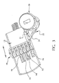
Fig. 2 is a perspective, separate view of the pawl, actuator, locking element, lock plug and retainer of the latch ofFig. 1 , shown in the locked condition. -
Fig. 3 is a perspective, separate view of the pawl, actuator, locking element, lock plug and retainer of the latch ofFig. 1 , shown with the lock plug and retainer in the locked condition, with the pawl in a partially returned position. -
Fig. 4 is a perspective, separate view of a retaining member of the latch ofFig. 1 . -
Fig. 5 , is a perspective, separate view of the handle of the latch ofFig. 1 . -
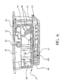
Fig. 6 is a left side, perspective view of the latch ofFig. 1 , illustrated with the housing shown in sectional view. -
Fig. 7 is a perspective, separate view of the pawl member of the latch ofFig. 1 , as viewed from the bottom, front side thereof -
Fig. 8 is a perspective, separate view of the housing of the latch ofFig.1 , as viewed from the top, right front thereof. -
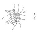
Fig. 9 is a perspective, separate view of the actuator of the latch ofFig.1 . -
Fig. 10 is a top plan, separate view of the housing of the latch shown inFig.1 . -
Fig. 11 is a top plan, separate view of the pawl member of the latch ofFig. 1 . -
Fig. 12 is a sectional view of the housing shown inFig. 10 , taken longitudinally therethrough. -
Fig. 13 is a front parallel perspective view of a second alternate embodiment of a latch according to the present invention. -
Fig. 14 is a rear parallel perspective view of the second alternate latch embodiment shown inFig. 13 , viewed from the back with the handle in the open position. -
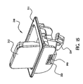
Fig. 15 is a front parallel perspective view of the second alternate latch embodiment shown inFig. 14 , viewed from the front right side with the handle in the open position. -
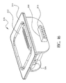
Fig. 16 is a front parallel perspective view of a third alternate embodiment of a latch according to the present invention. -
Fig. 17 is a sectional view of the third alternate embodiment of the latch shown inFig. 16 . -
Fig. 18 is a rear parallel perspective view of the third alternate embodiment of the latch ofFigs. 16 and17 , shown with the handle lifted and in the open condition. - Reference being made to
Fig. 1 , where a first alternate embodiment of alatch 10 according to the present invention is shown comprising a latch body orhousing 11, ahandle 12, apawl member 13, and anactuator 14. Biasing means for biasing thepawl member 13 toward a latching position is shown comprising aspring 15. - The
housing 11 has anupper flange 25 which defines the perimeter of thelatch 10. Mounting means is provided on thehousing 11, and preferably, for example, can comprise posts, such as those 26, which, for example, can have a bore with threads for receiving a matingly threaded bolt (not shown) for attachment of thelatch 10 to a panel member (not shown). It will be understood that any suitable mounting members, such as, rivets, screws, pins, barbs and the like can be used to secure thehousing 11 to a panel. Preferably, thelatch 10 can be installed on a floor panel of a vehicle to regulate access to and from a compartment. - Locking means is also provided to lock the
latch 10 against unauthorized opening. The locking means is shown comprising alock plug 20 which has akey slot 28 therein. Preferably, thehousing 11 has asocket 19 in which thelock plug 20 is installed. The locking means further includes a lockingelement 21, and retaining means for retaining thelock plug 20 on thehousing 11. The retaining means is shown comprising a retainingmember 22 which is disposed on a connecting end 27 of thelockplug 20 located on the lockplug end opposite of thekey slot 28 end. Preferably, the retainingmember 22 comprises a spring member and is flexible. - The retaining
element 22 secures thelock plug 20 and further is provided to selectively engage the lockingelement 21, as shown best inFigs. 2 and3 , to lock theactuator 14 from movement and thereby maintain thepawl member 13 in a latched position. Referring toFig. 4 , the retainingmember 22 has anarm 24 which extends outwardly therefrom for engagement with the locking element 21 (Figs. 2 and3 ).Figs. 2 and3 show the retainingmember 22 installed on the lock plug-connecting end 27. As shown inFig. 4 , the retainingmember 22 has anassembly slot 30 for facilitating snap-fit installation onto thelock plug 20.Detents member 22 for indicating the stop positions of the retainingmember 22 when the lock plug is rotated with a key (not shown). The retainingmember 22 is configured to be rotated by thelock plug 20 with the operation of a key (not shown) inserted and rotated in thekey slot 28. - Referring to
Fig. 5 , thehandle 12 is shown in a separate view having abody 37 with a liftingportion 40, a pair offlanges handle 12, and mounting means for mounting thehandle 12 to thehousing 11, the mounting means comprising a pair ofpivot bosses flanges actuator 14 is provided on the front of thehandle 12 opposite the liftingportion 40. The contact means is shown comprising atab 43 disposed on thehandle body 37. Thehandle 12 further has arecess 49 provided for accommodating thelock plug 20, by permitting the top of thelock plug 20 to reside in therecess 49 when thehandle 12 is closed. - Reference now being made to
Fig. 6 , thetab 43 is provided to engage with the front of theactuator 14, when thehandle 12 is pivoted by lifting. This lifting of thehandle 12 draws theactuator 14 rearwardly within thehousing 11 and through its engagement with thepawl 13, theactuator 14 retracts thepawl member 13 inwardly toward thehousing 11. As shown inFig. 1 , aslot 50 is disposed in thefront wall 49 of thehousing 11 for receiving thepawl member 13 therein. Theslot 50, preferably, is matingly configured to accommodate thepawl 13 and facilitate the movement of thepawl member 13 therein. - The
housing slot 50 preferably can be provided with strengtheningribs slot 50. Theslot 50 is shown having a pair oftracks pawl 13. Thepawl member 14, as shown inFig. 7 , has surfaces 57,58 which facilitate sliding of thepawl 13 along thetracks housing slot 50. - As shown in
Fig. 1 , thehousing 11 has a pair ofapertures pivot bosses handle 12 are carried in thepivot apertures handle 12 on thehousing 11. Referring toFigs. 1 and5 , thehandle 12 hasside flanges handle 12 relative to thehousing 11. Thehousing 11 is provided with afirst side ledge 64 and asecond side ledge 65 disposed on each side thereof. Thefirst side ledge 64 provides a seat for thehandle side flange 38 when thehandle 12 is in its closed (Fig. 1 ) position. Similarly, thesecond side ledge 65 provides a seat for thesecond flange 39 on the opposite handle side. Preferably, the first andsecond ledges handle 12 slightly off of the top of thelock plug 20. Alternately, thelock plug 20 can be utilized to further stabilize the latch handle 12 by providing an additional seat on which thehandle 12 may rest. This is accomplished by arranging the flanges and heights of the first and second side ledges to correspond to the height of thelock plug 20. - Referring to
Fig. 9 , theactuator 14 is shown having handle engaging means for engaging with thehandle 12. The handle engaging means is shown comprising a plurality ofcontact ribs 70 which are angled to maximize the contact with thehandle tab portion 43 when thehandle 12 is pivoted to engage theactuator 14. Thecontact ribs 70 are shown supported on a shelf orbase 69 of the actuator. Theactuator 14 further has connecting means for connecting with thepawl member 13 to retract and release thepawl 13. The connecting means is shown comprisingsnap legs base 69 and are provided with atapered flange portions leg element 21. The stop means is shown comprising astop leg member 75 extending downwardly from the shelf orbase 69 of theactuator 14. Preferably, thestop leg 75 is provided on the outer end of theactuator 14 to facilitate interaction with the lockingelement 21. Referring toFig. 1 , theactuator stop leg 75 is provided with a widened portion, such as thehead 76, disposed facing and in a position for engaging the lockingelement 21. Theactuator 14 further comprises supporting means for supporting theactuator 14 in relation to thepawl 13 andhousing 11. The supporting means are best shown inFig. 9 comprising supportinglegs base 69 of theactuator 14. -
Fig. 10 shows thehousing 11 with afloor 80 having a plurality ofslots slots snap legs leg 75, and supportinglegs housing floor 80 and into thepawl 13. - The
pawl 13 is shown having a plurality ofslots legs actuation member 14 which extend into theslots Figs. 1 and8 , thehousing 11 is shown having apawl slot 50 which is matingly configured to slidably carry thepawl 13 therein. The mating configuration of theslot 50 facilitates alignment of theslots housing slots actuator 14 to extend through the pawl slots. Theouter slot 85 of thepawl member 13 is partially open on a side thereof. Thestop leg 75 of the actuator extends through theouter slot 85. As shown best inFigs. 2 and3 , the lockingelement 21 is positioned in theouter slot 85 for selective engagement with the retainingmember arm 24. The lockingelement 21 is maintained within thepawl slot 50 of thehousing 11. As shown inFig. 6 , thepawl slot 50 is defined by thehousing floor 80, which defines the top of theslot 50, arear wall 101, and abottom wall 102. Thepawl 13,spring 15, and lockingelement 21 are held between thefloor 80 and thebottom wall 102. - The
pawl 13 is biased with the force of thespring 15 into a forward, engaging position, where thepawl 13 protrudes outwardly from thehousing 11. After thepawl 13 has been retracted, the bias from thespring 15 further operates against thepawl 13 to return the pawl to its forward, latching position. Thepawl 13 is withdrawn by lifting thehandle 12, which forces thehandle tab 43 into engagement with the contactingribs 70 of theactuator 14. Theactuator 14 is then forced rearwardly in thehousing 11, with thelegs respective pawl slot stop leg 75 engaging against the lockingelement 21. The configuration of thepresent latch 10 allows thepawl 13 to be forced inward into theslot 50 of thehousing 11 when encountering a force, such as that from a keeper (not shown). This permits thelatch 10 to be slam locked, even when the retainingmember 22 is in the locked position. Thepawl 13 can be depressed inwardly and the lockingmember 21 will be accommodated by theouter slot 85 of thepawl 13, when the pawl is forced inward. Of course, thepawl 13, after being forced inward, once it clears a keeper and encounters no further resistance, is biased by thespring 15 toward its outward position, to secure thelatch 10. - As shown in
Figs. 1 and12 , detent means for holding thehandle 12 in the raised position is shown comprising a resilient engagingelement housing 11. The detent means preferably can maintain thehandle 12 in a raised position until the detent force is overcome by lowering thehandle 12. - Referring to
Fig. 13 , a second alternate embodiment of alatch 210 according to the present invention is shown. Thelatch 210 is similar to thelatch 10 of the first embodiment shown and described herein, but having an alternate locking mechanism and analternate pawl 213, which is configured having a rectangular cross-section to slide within aspace 250 provided in thehousing 211. The alternate locking mechanism shows locking means comprising alock plug 222 with a lockingpawl arm 224. The lockingpawl arm 224 is preferably a spring member to permit slam-action closing of thelatch 210 in both conditions, when the lockingpawl arm 224 is in the latching (Fig. 12 ) position, and when the lockingpawl 224 is rotated to the side, as shown inFig. 13 , in the open position. The spring force furnished with the lockingpawl arm 224 enables the lockingpawl arm 224 to snap over a keeper (not shown), and into its locking position. - As shown in
Fig. 14 , thehandle 212 is lifted and thehandle tab 243 engages theactuator 214 to retract thepawl 213 inwardly within the housing slot 250 (Fig. 15 ). - Reference now being made to
Figs. 16-18 where a third alternate embodiment of alatch 310 is shown according to the present invention. Thelatch 310 is provided to operate similar to the latch of thesecond embodiment 210 described above, but without a lock. Thelatch 310 is shown having ahousing 311, ahandle 312 pivotally connected thereto, apawl 313 disposed to slide in aslot 350 of thehousing 311, anactuator 314, and aspring 315 which biases thepawl 313 toward a latching position, to protrude outwardly from thehousing 311. Theactuator 314 can connect with thepawl 313 through a plurality of slots, such as that 370, shown inFig. 17 , which are provided on thehousing floor 380. Thehandle tab 343 is provided to engage theactuator 314 when thehandle 312 is lifted, as shown inFig. 18 . Other features, while not shown, such as the detent means described above in connection with thelatch 10, can also be employed with thelatch 310. Theactuator 314 can comprise the same configuration with the same legs as those described above in connection with theactuator 14 of the first embodiment of thelatch 10. - As shown in
Fig. 16 mounting means is provided on thehousing 311, comprising bores, such as that 326 (there being one or more additional bores, not shown). - One or more of the features described herein in connection with a latch embodiment disclosed herein, can be employed with another latch embodiment consistent with the principles of the applicant's present invention. Other modifications to the above description can be made consistent with the spirit and scope of the invention disclosed herein. For example, while the keeper is referred to as a separate member, it will be understood that the keeper can comprise a panel, enclosure frame or other surface which the pawl can engage, consistent with the disclosure provided herein. Also, while the present invention is described in connection with a lockplug, it is also understood that a knob, handle or other member can be used to rotate a member into and out of the way of the actuator or secondary keeper such as with the second alternate embodiment) to regulate the opening and closing.
- While the above description constitutes the preferred embodiment of the present invention, it will be appreciated, that the invention is subject to modification, variation and change, without departing from the proper scope or fair meaning of the present invention as defined by the appended claims. In this regard, while the various features of the present invention have been shown and described in relation to a vehicle floor panel, it will be understood that many of these features are suitable in connection with latching of other members.
Claims (19)
- A latch (10) for securing a first member to a second member, said latch (10) comprising:a) a housing (11) which is adapted for mounting to the first member,b) a pawl member (13) slidably supported by said housing (11), said pawl member (13) being movable between extended and retracted positions, and said pawl member (13) being adapted to secure the first member relative to the second member when said pawl member (13) is in said extended position and the first member is in a closed position relative to the second member,c) biasing means comprising a spring (15) for biasing said pawl (13) toward said extended position,d) a handle (12) pivotally supported by said housing (11) and being moveable over a pivot range including open and closed positions, ande) an actuator (14) for engaging said pawl member (13) and at least moving said pawl member (13) from said extended position toward said retracted position in response to pivotal movement of said handle (12) from said closed position toward said open position, said actuator (14) being slidably supported by said housing (11),
characterised in thatf) said actuator (14) being slidably supported by said housing (11) such that said actuator (14) moves rearwardly relative to said housing (11) in response to said handle (12) moving toward said open position,g) said pawl member (13) having a plurality of slots (91, 92, 93 ,94 ,95);h) said actuator (14) includes a base (69) and a plurality of legs (71, 72) which extend downward from said base (69) and into said plurality of slots (91, 92, 93 ,94 ,95) provided in said pawl member (13), and wherein said plurality of legs (71, 72) engage rearward ends of said plurality of slots (91, 92, 93 ,94 ,95) provided in said pawl member (13) as said handle (12) is pivotally moved to retract said pawl member (13). - The latch of claim 1, wherein said actuator (14) Includes a plurality of contact ribs (70) extending upward from said base (69), wherein said plurality of contact ribs (70) are engaged by said handle (12) during movement of said handle (12) toward said open position.
- The latch of claim 2, wherein said plurality of contact ribs (70) are angled to maximize contact with said handle (12) during movement of said handle (12) toward said open position.
- The latch of claim 1, wherein said housing (11) comprises a seat (64, 65) on each side thereof for supporting said handle (12) in said closed position.
- The latch of claim 4, wherein said handle (12) has a top surface and a flange (38, 39) disposed on each side of said top surface extending downwardly therefrom, wherein each said flange (38, 39) engages said housing seat (64, 65) to position said handle (12) relative to said housing (11).
- The latch of claim 1, wherein said housing (11) has detents for holding the handle (12) in a raised position.
- The latch of claim 1, further comprising:a lock plug (20) supported by said housing (11) for selective rotations between locked and unlocked positions, anda retaining member (22) attached to said lock plug (20) so as to move rotationally with said lock plug (20) between locked and unlocked positions, said retaining member (22) having an arm (24) that interferes with rearward movement of said actuator (14) when said lock plug (20) is in said locked position such that movement of said pawl (13) to said retracted position by actuation of said handle (12) is prevented.
- The latch of claim 7, wherein said pawl member (13) has a plurality of slots (91, 92, 93, 94, 95),
wherein said actuator (14) includes a base (69), a plurality of contact ribs (70) extending upward from said base (69) and
wherein said plurality of contact ribs (70) are engaged by said handle (12) during movement of said handle (12) toward said open position. - The latch of claim 8, wherein said plurality of contact ribs (70) are angled to maximize contact with said handle (12) during movement of said handle (12) toward said open position.
- The latch of claim 7, wherein said housing (11) comprises a seat (64, 65) on each side thereof for supporting said handle (12) In said closed position.
- The latch of claim 10, wherein said handle (12) has a top surface and a flange (38, 39) disposed on each side of said top surface extending downwardly therefrom, wherein each said flange (38, 39) engages said housing seat (64, 65) to position said handle (12) relative to said housing (11).
- The latch of claim 7, wherein said housing (11) has detents for holding the handle (12) in a partially raised position.
- The latch of claim 1, further comprising:a lock plug (20) supported by said housing (11) for selective rotation between locked and unlocked positions, anda locking pawl arm (24) attached to said lock plug (20) so as to move rotationally with said lock plug (20) between locked and unlocked positions, said locking pawl arm (24) engaging the second member or a keeper fixedly located relative to the second member when said lock plug (20) is in said locked position such that the first member remains secured in a closed position relative to the second member.
- The latch of claim 13, wherein said locking pawl arm (24) is resilient such that the first member can be moved to the closed position relative to the second member even with said lock plug in said locked position.
- The latch of claim 13, wherein said pawl member (13) has a plurality of slots (91, 92, 93, 94 ,95),
wherein said actuator (14) includes a base (69), a plurality of contact ribs (70) extending upward from said base (69) and
wherein said plurality of contact ribs (70) are engaged by said handle during movement of said handle (12) toward said open position. - The latch of claim 15, wherein said plurality of contact ribs (70) are angled to maximize contact with said handle (12) during movement of said handle (12) toward said open position.
- The latch of claim 13, wherein said housing (11) comprises a seat (64, 65) on each side thereof or supporting said handle (12) in said closed position.
- The latch of claim 17, wherein said handle (12) has a top surface and a flange (38, 39) disposed on each side of said top surface extending downwardly therefrom, wherein each said flange (38, 39) engages said housing seat (64, 65) to position said handle (12) relative to said housing (11).
- The latch of claim 13, wherein said housing (11) has detents for holding the handle (12) In a partially raised position.
Applications Claiming Priority (3)
| Application Number | Priority Date | Filing Date | Title |
|---|---|---|---|
| US25558699A | 1999-02-22 | 1999-02-22 | |
| US255586 | 1999-02-22 | ||
| PCT/US2000/004540 WO2000048870A1 (en) | 1999-02-22 | 2000-02-22 | Load floor latch |
Publications (3)
| Publication Number | Publication Date |
|---|---|
| EP1224099A1 EP1224099A1 (en) | 2002-07-24 |
| EP1224099A4 EP1224099A4 (en) | 2009-11-11 |
| EP1224099B1 true EP1224099B1 (en) | 2012-08-22 |
Family
ID=22968981
Family Applications (2)
| Application Number | Title | Priority Date | Filing Date |
|---|---|---|---|
| EP00913601A Withdrawn EP1163131A1 (en) | 1999-02-22 | 2000-02-22 | Load floor latch |
| EP00908772A Expired - Lifetime EP1224099B1 (en) | 1999-02-22 | 2000-02-22 | Load floor latch |
Family Applications Before (1)
| Application Number | Title | Priority Date | Filing Date |
|---|---|---|---|
| EP00913601A Withdrawn EP1163131A1 (en) | 1999-02-22 | 2000-02-22 | Load floor latch |
Country Status (4)
| Country | Link |
|---|---|
| EP (2) | EP1163131A1 (en) |
| KR (2) | KR100704477B1 (en) |
| AU (3) | AU3005200A (en) |
| WO (3) | WO2000048872A1 (en) |
Families Citing this family (5)
| Publication number | Priority date | Publication date | Assignee | Title |
|---|---|---|---|---|
| US6786518B2 (en) * | 2000-06-13 | 2004-09-07 | Southco, Inc. | Load floor latch |
| US6719332B2 (en) * | 2000-12-03 | 2004-04-13 | Southco, Inc. | Load floor latch |
| DE102004039930A1 (en) | 2003-08-18 | 2005-05-19 | Southco, Inc. | loading area closure |
| EP3469171B1 (en) * | 2016-06-13 | 2023-05-10 | Howmet Aerospace Inc. | Rotary latch system |
| DE202017107662U1 (en) * | 2017-12-15 | 2018-01-15 | Abb Schweiz Ag | Handle element for receiving in the front of a door of a cabinet, in particular control cabinet |
Family Cites Families (12)
| Publication number | Priority date | Publication date | Assignee | Title |
|---|---|---|---|---|
| US2186903A (en) | 1938-11-16 | 1940-01-09 | Pennsylvania Railroad Co | Latch |
| US2987908A (en) * | 1959-02-12 | 1961-06-13 | Eastern Malleable Iron Company | Door lock |
| US3782141A (en) * | 1972-10-26 | 1974-01-01 | Hansen Mfg Co A L | Flush type door latch |
| EP0030984A1 (en) * | 1979-12-20 | 1981-07-01 | Willi Eigemeier | Door lock with latch and bolt |
| US4312202A (en) | 1979-12-28 | 1982-01-26 | The Eastern Company | Paddle lock with bolt-carried handle disconnect member |
| US4438964A (en) * | 1981-06-18 | 1984-03-27 | Pierce Manufacturing, Inc. | Paddle operated vehicle latch |
| US4683736A (en) * | 1984-04-18 | 1987-08-04 | The Eastern Company | Cabinet lock with recessed handle |
| US5297404A (en) * | 1992-07-06 | 1994-03-29 | Hsl Marketing, Inc. | Bolt for an inner cylinder lock |
| KR970006041U (en) * | 1995-07-12 | 1997-02-21 | Handle for opening and closing the door | |
| KR970062653U (en) * | 1996-05-22 | 1997-12-11 | Handle Pull on Vehicle Door | |
| KR19980021952U (en) * | 1996-10-24 | 1998-07-15 | 박병재 | Outside handle balance weight of car door |
| US5897147A (en) * | 1997-01-08 | 1999-04-27 | Southco, Inc. | Locking slide latch |
-
2000
- 2000-02-22 WO PCT/US2000/004720 patent/WO2000048872A1/en not_active Ceased
- 2000-02-22 AU AU30052/00A patent/AU3005200A/en not_active Abandoned
- 2000-02-22 WO PCT/US2000/004541 patent/WO2000048871A1/en not_active Ceased
- 2000-02-22 EP EP00913601A patent/EP1163131A1/en not_active Withdrawn
- 2000-02-22 AU AU30051/00A patent/AU3005100A/en not_active Abandoned
- 2000-02-22 AU AU35016/00A patent/AU3501600A/en not_active Abandoned
- 2000-02-22 WO PCT/US2000/004540 patent/WO2000048870A1/en not_active Ceased
- 2000-02-22 EP EP00908772A patent/EP1224099B1/en not_active Expired - Lifetime
- 2000-02-22 KR KR1020017010603A patent/KR100704477B1/en not_active Expired - Lifetime
- 2000-02-22 KR KR1020017009911A patent/KR100638082B1/en not_active Expired - Fee Related
Also Published As
| Publication number | Publication date |
|---|---|
| KR100638082B1 (en) | 2006-10-24 |
| EP1163131A1 (en) | 2001-12-19 |
| AU3005200A (en) | 2000-09-04 |
| WO2000048871A1 (en) | 2000-08-24 |
| AU3501600A (en) | 2000-09-04 |
| WO2000048870A1 (en) | 2000-08-24 |
| EP1224099A1 (en) | 2002-07-24 |
| WO2000048872A1 (en) | 2000-08-24 |
| KR20010101787A (en) | 2001-11-14 |
| AU3005100A (en) | 2000-09-04 |
| KR100704477B1 (en) | 2007-04-09 |
| KR20020016616A (en) | 2002-03-04 |
| EP1224099A4 (en) | 2009-11-11 |
Similar Documents
| Publication | Publication Date | Title |
|---|---|---|
| US7052053B2 (en) | Load floor latch | |
| US6626472B1 (en) | Load floor latch | |
| US5927772A (en) | Ratcheting pawl latch | |
| US7399009B2 (en) | Load floor latch | |
| US6048006A (en) | Ratcheting pawl latch | |
| US6109669A (en) | Load floor slam-action paw latch | |
| US5878606A (en) | Door lock for swinging door | |
| KR100873845B1 (en) | Loading bottom latch | |
| CN108625693B (en) | Vehicle closing latch assembly with anti-slap latch mechanism | |
| US7083205B2 (en) | Double-acting load floor slam latch | |
| EP1330584B1 (en) | Latching device | |
| US7096538B2 (en) | Vehicle door hinge system | |
| WO2000048870A1 (en) | Load floor latch | |
| WO2001038671A2 (en) | Ratcheting pawl latch | |
| US6435572B1 (en) | Double pawl console latch | |
| EP1117887A1 (en) | Load floor slam-action pawl latch | |
| US4412695A (en) | Slide bolt latch assembly | |
| WO2000050715A1 (en) | Self-locking console latch | |
| MXPA00002398A (en) | Ratcheting pawl latch | |
| WO2001012925A9 (en) | Double console latch | |
| AU9385598A (en) | Ratcheting pawl latch |
Legal Events
| Date | Code | Title | Description |
|---|---|---|---|
| PUAI | Public reference made under article 153(3) epc to a published international application that has entered the european phase |
Free format text: ORIGINAL CODE: 0009012 |
|
| 17P | Request for examination filed |
Effective date: 20010907 |
|
| AK | Designated contracting states |
Kind code of ref document: A1 Designated state(s): DE ES FR GB IT |
|
| RIC1 | Information provided on ipc code assigned before grant |
Ipc: G05G 5/00 20060101ALI20090904BHEP Ipc: B60R 25/02 20060101AFI20000830BHEP Ipc: E05C 1/14 20060101ALI20090904BHEP Ipc: B62H 5/04 20060101ALI20090904BHEP Ipc: E05B 13/10 20060101ALI20090904BHEP Ipc: F16C 3/00 20060101ALI20090904BHEP |
|
| A4 | Supplementary search report drawn up and despatched |
Effective date: 20090910 |
|
| 17Q | First examination report despatched |
Effective date: 20100318 |
|
| RIC1 | Information provided on ipc code assigned before grant |
Ipc: B60R 25/02 20060101AFI20120120BHEP Ipc: B62H 5/04 20060101ALI20120120BHEP Ipc: E05C 1/14 20060101ALI20120120BHEP Ipc: E05B 13/10 20060101ALI20120120BHEP Ipc: G05G 5/00 20060101ALI20120120BHEP Ipc: F16C 3/00 20060101ALI20120120BHEP |
|
| GRAP | Despatch of communication of intention to grant a patent |
Free format text: ORIGINAL CODE: EPIDOSNIGR1 |
|
| GRAS | Grant fee paid |
Free format text: ORIGINAL CODE: EPIDOSNIGR3 |
|
| GRAA | (expected) grant |
Free format text: ORIGINAL CODE: 0009210 |
|
| AK | Designated contracting states |
Kind code of ref document: B1 Designated state(s): DE ES FR GB IT |
|
| REG | Reference to a national code |
Ref country code: GB Ref legal event code: FG4D |
|
| REG | Reference to a national code |
Ref country code: DE Ref legal event code: R096 Ref document number: 60047441 Country of ref document: DE Effective date: 20121018 |
|
| PG25 | Lapsed in a contracting state [announced via postgrant information from national office to epo] |
Ref country code: ES Free format text: LAPSE BECAUSE OF FAILURE TO SUBMIT A TRANSLATION OF THE DESCRIPTION OR TO PAY THE FEE WITHIN THE PRESCRIBED TIME-LIMIT Effective date: 20121203 |
|
| PG25 | Lapsed in a contracting state [announced via postgrant information from national office to epo] |
Ref country code: IT Free format text: LAPSE BECAUSE OF FAILURE TO SUBMIT A TRANSLATION OF THE DESCRIPTION OR TO PAY THE FEE WITHIN THE PRESCRIBED TIME-LIMIT Effective date: 20120822 |
|
| PLBE | No opposition filed within time limit |
Free format text: ORIGINAL CODE: 0009261 |
|
| STAA | Information on the status of an ep patent application or granted ep patent |
Free format text: STATUS: NO OPPOSITION FILED WITHIN TIME LIMIT |
|
| 26N | No opposition filed |
Effective date: 20130523 |
|
| REG | Reference to a national code |
Ref country code: DE Ref legal event code: R097 Ref document number: 60047441 Country of ref document: DE Effective date: 20130523 |
|
| GBPC | Gb: european patent ceased through non-payment of renewal fee |
Effective date: 20130222 |
|
| REG | Reference to a national code |
Ref country code: FR Ref legal event code: ST Effective date: 20131031 |
|
| PG25 | Lapsed in a contracting state [announced via postgrant information from national office to epo] |
Ref country code: GB Free format text: LAPSE BECAUSE OF NON-PAYMENT OF DUE FEES Effective date: 20130222 Ref country code: FR Free format text: LAPSE BECAUSE OF NON-PAYMENT OF DUE FEES Effective date: 20130228 |
|
| PGFP | Annual fee paid to national office [announced via postgrant information from national office to epo] |
Ref country code: DE Payment date: 20190212 Year of fee payment: 20 |
|
| REG | Reference to a national code |
Ref country code: DE Ref legal event code: R071 Ref document number: 60047441 Country of ref document: DE |