EP1223717A1 - Maximum likelihood detection method using a sequence estimation receiver - Google Patents
Maximum likelihood detection method using a sequence estimation receiver Download PDFInfo
- Publication number
- EP1223717A1 EP1223717A1 EP01300298A EP01300298A EP1223717A1 EP 1223717 A1 EP1223717 A1 EP 1223717A1 EP 01300298 A EP01300298 A EP 01300298A EP 01300298 A EP01300298 A EP 01300298A EP 1223717 A1 EP1223717 A1 EP 1223717A1
- Authority
- EP
- European Patent Office
- Prior art keywords
- symbol
- signal
- symbols
- received signal
- receiver
- Prior art date
- Legal status (The legal status is an assumption and is not a legal conclusion. Google has not performed a legal analysis and makes no representation as to the accuracy of the status listed.)
- Granted
Links
- 238000001514 detection method Methods 0.000 title claims abstract description 31
- 238000007476 Maximum Likelihood Methods 0.000 title 1
- 238000004891 communication Methods 0.000 claims abstract description 16
- 238000012937 correction Methods 0.000 claims description 21
- 238000000034 method Methods 0.000 claims description 10
- 230000000875 corresponding effect Effects 0.000 description 7
- 230000002596 correlated effect Effects 0.000 description 2
- 238000010586 diagram Methods 0.000 description 2
- 230000000694 effects Effects 0.000 description 2
- 230000001629 suppression Effects 0.000 description 2
- 238000013459 approach Methods 0.000 description 1
- 230000005540 biological transmission Effects 0.000 description 1
- 238000001914 filtration Methods 0.000 description 1
- 230000010363 phase shift Effects 0.000 description 1
- 238000012545 processing Methods 0.000 description 1
Images

Classifications
-
- H—ELECTRICITY
- H04—ELECTRIC COMMUNICATION TECHNIQUE
- H04L—TRANSMISSION OF DIGITAL INFORMATION, e.g. TELEGRAPHIC COMMUNICATION
- H04L25/00—Baseband systems
- H04L25/02—Details ; arrangements for supplying electrical power along data transmission lines
- H04L25/03—Shaping networks in transmitter or receiver, e.g. adaptive shaping networks
- H04L25/03006—Arrangements for removing intersymbol interference
- H04L25/03012—Arrangements for removing intersymbol interference operating in the time domain
- H04L25/03114—Arrangements for removing intersymbol interference operating in the time domain non-adaptive, i.e. not adjustable, manually adjustable, or adjustable only during the reception of special signals
- H04L25/03146—Arrangements for removing intersymbol interference operating in the time domain non-adaptive, i.e. not adjustable, manually adjustable, or adjustable only during the reception of special signals with a recursive structure
-
- H—ELECTRICITY
- H04—ELECTRIC COMMUNICATION TECHNIQUE
- H04L—TRANSMISSION OF DIGITAL INFORMATION, e.g. TELEGRAPHIC COMMUNICATION
- H04L25/00—Baseband systems
- H04L25/02—Details ; arrangements for supplying electrical power along data transmission lines
- H04L25/03—Shaping networks in transmitter or receiver, e.g. adaptive shaping networks
- H04L25/03006—Arrangements for removing intersymbol interference
- H04L2025/0335—Arrangements for removing intersymbol interference characterised by the type of transmission
- H04L2025/03375—Passband transmission
- H04L2025/03401—PSK
-
- H—ELECTRICITY
- H04—ELECTRIC COMMUNICATION TECHNIQUE
- H04L—TRANSMISSION OF DIGITAL INFORMATION, e.g. TELEGRAPHIC COMMUNICATION
- H04L25/00—Baseband systems
- H04L25/02—Details ; arrangements for supplying electrical power along data transmission lines
- H04L25/03—Shaping networks in transmitter or receiver, e.g. adaptive shaping networks
- H04L25/03006—Arrangements for removing intersymbol interference
- H04L2025/0335—Arrangements for removing intersymbol interference characterised by the type of transmission
- H04L2025/03375—Passband transmission
- H04L2025/0342—QAM
-
- H—ELECTRICITY
- H04—ELECTRIC COMMUNICATION TECHNIQUE
- H04L—TRANSMISSION OF DIGITAL INFORMATION, e.g. TELEGRAPHIC COMMUNICATION
- H04L25/00—Baseband systems
- H04L25/02—Details ; arrangements for supplying electrical power along data transmission lines
- H04L25/03—Shaping networks in transmitter or receiver, e.g. adaptive shaping networks
- H04L25/03006—Arrangements for removing intersymbol interference
- H04L2025/03433—Arrangements for removing intersymbol interference characterised by equaliser structure
- H04L2025/03439—Fixed structures
- H04L2025/03445—Time domain
- H04L2025/03471—Tapped delay lines
- H04L2025/03484—Tapped delay lines time-recursive
- H04L2025/0349—Tapped delay lines time-recursive as a feedback filter
-
- H—ELECTRICITY
- H04—ELECTRIC COMMUNICATION TECHNIQUE
- H04L—TRANSMISSION OF DIGITAL INFORMATION, e.g. TELEGRAPHIC COMMUNICATION
- H04L25/00—Baseband systems
- H04L25/02—Details ; arrangements for supplying electrical power along data transmission lines
- H04L25/03—Shaping networks in transmitter or receiver, e.g. adaptive shaping networks
- H04L25/03006—Arrangements for removing intersymbol interference
- H04L2025/03592—Adaptation methods
- H04L2025/03745—Timing of adaptation
- H04L2025/03764—Timing of adaptation only during predefined intervals
- H04L2025/0377—Timing of adaptation only during predefined intervals during the reception of training signals
Definitions
- the invention relates to a detection method using a receiver of a digital communication system for the detection of a symbol from a received signal, which signal is transmitted by a transmitter of the digital communication system, wherein the symbol is a selected symbol out of a predetermined set of symbols and wherein each symbol of the predetermined set comprises a sequence of chips wherein each of the chips is PSK-modulated according to a selected modulation code.
- Detection methods of this kind are known and find their applications in a variety of digital data communication systems. These data communication systems can for instance be wireless data communication systems. According to known methods the receiver of the data communication system detects a symbol by detecting successively the chips of the symbol. This is referred to as chip-by-chip detection. After the detection of each chip a correction signal for the Inter Chip Interference (ICI-effect) between neighbouring chips is generated and subtracted from the received signal.
- ICI-effect Inter Chip Interference
- a first disadvantage of known methods is that detecting on chip-by-chip basis gives rise to some loss of coding gain with respect to detecting an entire symbol at one go (this is detecting on symbol-by-symbol basis).
- a second disadvantage of known methods is that no use is made of the a priori knowledge of the predetermined set.
- the detection method of the invention is characterised in that a set of reference symbols is generated on the basis of the predetermined set of symbols and the channel impulse response between the transmitter and the receiver, wherein each of the successive parts of the received signal, each part having the length of a symbol, is compared with each of the reference symbols, yielding a detected symbol for each part of the received signal.
- This detection method yields an optimal coding gain since complete symbols are detected at one go.
- a priory knowledge of the predetermined is used by only comparing the received signal with reference symbols corresponding to symbols from the predetermined set.
- the latter approach also saves processing power with respect to a detection method wherein all possible combinations of chips are compared with the received signal.
- a further advantage of the method according to the invention is that the ICI-effect is maximally suppressed. This is caused by the fact that the ICI-effect has been taken into account implicitly in the generation of reference symbols. These reference symbols are created by convolving the symbols out of the predetermined set with the channel impulse response between the transmitter and the receiver.
- a preferred embodiment of the method according to the invention is characterised in that a correction signal is generated on the basis of the detected symbol convolved with the channel impulse response, wherein the correction signal is subtracted from the part of received signal which succeeds the part of the received signal corresponding to the detected symbol for suppressing the ISI-effect.
- the ISI-effect may occur (in an analogous way as the ICI-effect) as a consequence of TDS.
- the correction signal may be an estimated coefficient multiplied with the detected symbol convolved with the channel impulse response.
- a further embodiment of the method according to the invention is characterised in that the comparison between each of the parts of the received signal with each of the reference symbols is performed by a correlator yielding a correlation value, wherein the correlation value is corrected with half the energy of the reference symbol.
- An alternative embodiment of the detection method of the invention is characterised in that the received signal is filtered by a filter which yields a filter signal, wherein the filter is a matched filter to the channel impulse response between the transmitter and the receiver, wherein each of the successive parts of the filter signal, each part having the length of a symbol, is compared with each of the symbols from the predetermined set of symbols yielding a detected symbol for each part of the filter signal.
- the received signal is in a first step corrected for the channel impulse response between transmitter and receiver.
- a further embodiment of the alternative detection method according to the invention is characterised in that a correction signal is generated on the basis of the detected symbol, wherein the correction signal is subtracted from the part of filter signal which succeeds the part of the filter signal corresponding to the detected symbol for suppressing the ISI-effect.
- a still further embodiment of the alternative detection method according to the invention is characterised in that the comparison, between each of the parts of the filter signal with each of the reference symbols, is performed by a correlator yielding a correlation value, wherein the correlation value is corrected with half the energy of the reference symbol.
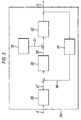
- a receiver 2 of a digital communication system for receiving a signal 4 and performing a detection, according to a detection method of the invention, of a symbol from the received signal 4 is shown in figure 1.
- the signal 4 is transmitted by a transmitter of the digital communication system to the receiver 2.
- the output 6 of the receiver 2 is the detected symbol from the received signal 4.
- the detected symbol is a selected symbol out of a predetermined set of symbols.
- Each symbol of the predetermined set comprises a sequence of chips wherein each of the chips is PSK-modulated according to a selected modulation code.
- An example of a symbol 8 of the predetermined set comprising eight chips C 1 up to and including C 8 is shown in figure 2.
- the receiver 2 comprises a set of correlation blocks 10.1 up to and including 10.M for performing correlations between the received signal 4 and reference symbols from a set of reference symbols, a decision block 12 for selecting one of said reference symbols, a feedback block 14 for generating a correction signal 15 for suppressing the Inter Symbol Interference effect (ISI-effect) and an estimation block 16 for generating-an estimation 18 of the channel impulse response between the transmitter and the receiver on the basis of a reference signal 20.
- ISI-effect Inter Symbol Interference effect
- the m th correlation block correlates the received signal 4 with the m th reference symbol S m from the set of M reference symbols.
- Each of the correlation values may be corrected with half the energy of the corresponding reference symbol in order to make the correlation values mutually comparable.
- these correlation values are the input to the decision block 12 which selects the reference symbol corresponding to the largest correlation value.
- the detected symbol is the symbol from the predetermined set of symbols which correspond with the selected reference symbol for the part of the received signal.
- the detected symbol is the output 6 of the receiver 2.
- Time Delay Spread is the effect wherein a received signal, which has been transmitted by a transmitter, has spread out in time with respect to the signal before transmission. This results in that a part of the signal may end up in another part of the received signal.
- the TDS-effect may occur as a result of multi-path in the channel between transmitter and receiver.
- the Inter Chip Interference (ICI-effect) is the result of the TDS-effect wherein a chip smears out over a neighbouring chip.
- the Inter Symbol Interference ISI-effect
- ISI-effect is the result of the TDS-effect wherein a symbol smears out over a neighbouring symbol.
- the receiver 2 performing a detection method according to the invention, effectively suppresses the ICI-effect since entire symbols are detected at one go by comparing entire symbols with reference symbols (this is called detection on symbol-by-symbol basis). Since the reference symbols are convoluted with the channel impulse response the ICI-effect is automatically accounted for.
- a feedback loop comprising the feedback block 14.
- the feedback block 14 calculates a correction signal 15 for the received signal 4.
- This correction signal 15 is a function of the detected symbol. This function may be an estimated coefficient multiplied with the detected symbol convolved with the channel impulse response between the transmitter and the receiver.
- the correction signal 15 is subtracted from the part of received signal which succeeds the part of the received signal corresponding to the detected symbol.
- the estimation 18 of the channel impulse response is performed by the estimation block 16 on the basis of the reference signal 20.
- FIG. 3 An alternative receiver 24 of a digital communication system for receiving a signal 4 and performing a detection method according to the invention of a symbol from the received signal 4 is shown in figure 3.
- the signal 4 is transmitted by a transmitter of the digital communication system to the receiver 24.
- the output 6 of the receiver 2 is the detected symbol from the received signal 4.
- the receiver 24 comprises a matched filter 26 on the channel between the transmitter an the receiver, a correlator-bank 28 comprising a set of correlators, an correction block 30 for generating correction terms 31 for the output of the correlator-bank 28, a decision block 32 for selecting a detected symbol from the predetermined set of symbols and a feedback-block 34 for generating a correction signal 36 for suppressing the ISI-effect.
- the first step in the receiver 24 is the filtering of the received signal 4 by the channel matched filter block 26, resulting in the filter signal 27.
- the filter signal 27 is fed to a correlator-bank 28 comprising M correlators, wherein successive parts of the filter signal 27 are correlated with each of the M symbols from the predetermined set of symbols. This yields an output 29 of the correlator-bank 28 of M correlation values per part of the filter signal 27.
- the m th correlation value results from the correlation between the part of the filter signal 27 and the m th symbol from the predetermined set of symbols.
- Each of the correlation values is corrected by the correction block 30 with a correction value 31 in order to generate correlation values which are mutually comparable. In this example the correction value is half the energy of the corresponding symbol.
- the decision block 32 selects the symbol from the predetermined set of symbols which corresponds to the largest correlation value, this selected symbol is the detected symbol 6. Since the detection of the symbol is performed on symbol-by-symbol basis the ICI-effect is effectively suppressed (in an analogous way as described hereinbefore in relation to receiver 2). The suppression of the ISI-effect is suppressed with a feedback loop wherein the feedback block 34 generates a correction signal 36 on the basis of the detected symbol 6. (in an analogous way as described hereinbefore in relation to receiver 2).
- amplitude modulation can be used in combination with PSK-modulation.
Landscapes
- Engineering & Computer Science (AREA)
- Power Engineering (AREA)
- Computer Networks & Wireless Communication (AREA)
- Signal Processing (AREA)
- Digital Transmission Methods That Use Modulated Carrier Waves (AREA)
- Noise Elimination (AREA)
Abstract
Description
- The invention relates to a detection method using a receiver of a digital communication system for the detection of a symbol from a received signal, which signal is transmitted by a transmitter of the digital communication system, wherein the symbol is a selected symbol out of a predetermined set of symbols and wherein each symbol of the predetermined set comprises a sequence of chips wherein each of the chips is PSK-modulated according to a selected modulation code.
- Detection methods of this kind are known and find their applications in a variety of digital data communication systems. These data communication systems can for instance be wireless data communication systems. According to known methods the receiver of the data communication system detects a symbol by detecting successively the chips of the symbol. This is referred to as chip-by-chip detection. After the detection of each chip a correction signal for the Inter Chip Interference (ICI-effect) between neighbouring chips is generated and subtracted from the received signal.
- A first disadvantage of known methods is that detecting on chip-by-chip basis gives rise to some loss of coding gain with respect to detecting an entire symbol at one go (this is detecting on symbol-by-symbol basis). A second disadvantage of known methods is that no use is made of the a priori knowledge of the predetermined set.
- It is an object of the invention to provide in a detection method which yields an optimal coding gain by detecting an entire symbol at one go. It is also an object of the invention to provide in a detection method which uses a priory knowledge of the predetermined set. For this, the detection method of the invention is characterised in that a set of reference symbols is generated on the basis of the predetermined set of symbols and the channel impulse response between the transmitter and the receiver, wherein each of the successive parts of the received signal, each part having the length of a symbol, is compared with each of the reference symbols, yielding a detected symbol for each part of the received signal. This detection method yields an optimal coding gain since complete symbols are detected at one go. Furthermore, a priory knowledge of the predetermined is used by only comparing the received signal with reference symbols corresponding to symbols from the predetermined set. The latter approach also saves processing power with respect to a detection method wherein all possible combinations of chips are compared with the received signal. A further advantage of the method according to the invention is that the ICI-effect is maximally suppressed. This is caused by the fact that the ICI-effect has been taken into account implicitly in the generation of reference symbols. These reference symbols are created by convolving the symbols out of the predetermined set with the channel impulse response between the transmitter and the receiver.
- A preferred embodiment of the method according to the invention is characterised in that a correction signal is generated on the basis of the detected symbol convolved with the channel impulse response, wherein the correction signal is subtracted from the part of received signal which succeeds the part of the received signal corresponding to the detected symbol for suppressing the ISI-effect. The ISI-effect may occur (in an analogous way as the ICI-effect) as a consequence of TDS. In the detection method of the invention each time a part of the received signal with the length of a symbol is corrected for the ISI-effect as soon as a symbol from the preceding part with the length of a symbol of the received signal is detected. The correction signal may be an estimated coefficient multiplied with the detected symbol convolved with the channel impulse response.
- A further embodiment of the method according to the invention is characterised in that the comparison between each of the parts of the received signal with each of the reference symbols is performed by a correlator yielding a correlation value, wherein the correlation value is corrected with half the energy of the reference symbol.
- An alternative embodiment of the detection method of the invention is characterised in that the received signal is filtered by a filter which yields a filter signal, wherein the filter is a matched filter to the channel impulse response between the transmitter and the receiver, wherein each of the successive parts of the filter signal, each part having the length of a symbol, is compared with each of the symbols from the predetermined set of symbols yielding a detected symbol for each part of the filter signal. In this embodiment the received signal is in a first step corrected for the channel impulse response between transmitter and receiver.
- A further embodiment of the alternative detection method according to the invention is characterised in that a correction signal is generated on the basis of the detected symbol, wherein the correction signal is subtracted from the part of filter signal which succeeds the part of the filter signal corresponding to the detected symbol for suppressing the ISI-effect.
- A still further embodiment of the alternative detection method according to the invention is characterised in that the comparison, between each of the parts of the filter signal with each of the reference symbols, is performed by a correlator yielding a correlation value, wherein the correlation value is corrected with half the energy of the reference symbol.
- In the accompanying drawings, in which certain modes of carrying out the present invention are schematically shown for illustrative purposes:
- Figure 1 is a diagram schematically showing a receiver for performing a detection method according to the invention;
- Figure 2 presents a symbol comprising eight chips, wherein each chip is Phase Shift Keying Modulated;
- Figure 3 is a diagram schematically showing an alternative receiver for performing a detection method according to the invention.
-
- A
receiver 2 of a digital communication system for receiving asignal 4 and performing a detection, according to a detection method of the invention, of a symbol from the receivedsignal 4 is shown in figure 1. Thesignal 4 is transmitted by a transmitter of the digital communication system to thereceiver 2. Theoutput 6 of thereceiver 2 is the detected symbol from the receivedsignal 4. The detected symbol is a selected symbol out of a predetermined set of symbols. Each symbol of the predetermined set comprises a sequence of chips wherein each of the chips is PSK-modulated according to a selected modulation code. An example of asymbol 8 of the predetermined set comprising eight chips C1 up to and including C8 is shown in figure 2. - The
receiver 2 comprises a set of correlation blocks 10.1 up to and including 10.M for performing correlations between the receivedsignal 4 and reference symbols from a set of reference symbols, adecision block 12 for selecting one of said reference symbols, afeedback block 14 for generating acorrection signal 15 for suppressing the Inter Symbol Interference effect (ISI-effect) and anestimation block 16 for generating-anestimation 18 of the channel impulse response between the transmitter and the receiver on the basis of areference signal 20. - In a first step of the detection method of the
receiver 2 the receivedsignal 4 is correlated with symbols from a set of reference symbols. These correlations are performed by a set of M correlation blocks 10.m (m=1,...,M). In this example the mth correlation block correlates the receivedsignal 4 with the mth reference symbol Sm from the set of M reference symbols. The correlations are performed between successive parts of the receivedsignal 4 wherein each part has the length of a symbol. This yields M correlation values 22.m (m=1, ..., M) per part of the received signal. Each of the correlation values may be corrected with half the energy of the corresponding reference symbol in order to make the correlation values mutually comparable. Next, these correlation values are the input to thedecision block 12 which selects the reference symbol corresponding to the largest correlation value. The detected symbol is the symbol from the predetermined set of symbols which correspond with the selected reference symbol for the part of the received signal. The detected symbol is theoutput 6 of thereceiver 2. - Time Delay Spread (TDS) is the effect wherein a received signal, which has been transmitted by a transmitter, has spread out in time with respect to the signal before transmission. This results in that a part of the signal may end up in another part of the received signal. The TDS-effect may occur as a result of multi-path in the channel between transmitter and receiver. The Inter Chip Interference (ICI-effect) is the result of the TDS-effect wherein a chip smears out over a neighbouring chip. The Inter Symbol Interference (ISI-effect) is the result of the TDS-effect wherein a symbol smears out over a neighbouring symbol. The
receiver 2, performing a detection method according to the invention, effectively suppresses the ICI-effect since entire symbols are detected at one go by comparing entire symbols with reference symbols (this is called detection on symbol-by-symbol basis). Since the reference symbols are convoluted with the channel impulse response the ICI-effect is automatically accounted for. - For the suppression of the ISI-effect in the detection method performed by the receiver 2 a feedback loop is used comprising the
feedback block 14. Thefeedback block 14 calculates acorrection signal 15 for the receivedsignal 4. Thiscorrection signal 15 is a function of the detected symbol. This function may be an estimated coefficient multiplied with the detected symbol convolved with the channel impulse response between the transmitter and the receiver. Thecorrection signal 15 is subtracted from the part of received signal which succeeds the part of the received signal corresponding to the detected symbol. - The M reference symbols Sm (m=1, ..., M) are obtained by convoluting the symbols from the predetermined set with the channel impulse response between the transmitter and the receiver. This implicates that the symbols from the set of reference symbols have to be re-calculated regularly and at least every time when the channel impulse response has changed. The
estimation 18 of the channel impulse response is performed by theestimation block 16 on the basis of thereference signal 20. Theestimation 18 is fed to the correlation blocks 10.m (m=1,...,M). Then, the mth correlation block calculates the reference symbol Sm (m=1, ..., M) which is used for correlations to be performed by the mth correlator. - An
alternative receiver 24 of a digital communication system for receiving asignal 4 and performing a detection method according to the invention of a symbol from the receivedsignal 4 is shown in figure 3. Thesignal 4 is transmitted by a transmitter of the digital communication system to thereceiver 24. Theoutput 6 of thereceiver 2 is the detected symbol from the receivedsignal 4. Thereceiver 24 comprises a matchedfilter 26 on the channel between the transmitter an the receiver, a correlator-bank 28 comprising a set of correlators, ancorrection block 30 for generatingcorrection terms 31 for the output of the correlator-bank 28, adecision block 32 for selecting a detected symbol from the predetermined set of symbols and a feedback-block 34 for generating acorrection signal 36 for suppressing the ISI-effect. - The first step in the
receiver 24 is the filtering of the receivedsignal 4 by the channel matchedfilter block 26, resulting in thefilter signal 27. Thefilter signal 27 is fed to a correlator-bank 28 comprising M correlators, wherein successive parts of thefilter signal 27 are correlated with each of the M symbols from the predetermined set of symbols. This yields anoutput 29 of the correlator-bank 28 of M correlation values per part of thefilter signal 27. The mth correlation value results from the correlation between the part of thefilter signal 27 and the mth symbol from the predetermined set of symbols. Each of the correlation values is corrected by thecorrection block 30 with acorrection value 31 in order to generate correlation values which are mutually comparable. In this example the correction value is half the energy of the corresponding symbol. Thedecision block 32 selects the symbol from the predetermined set of symbols which corresponds to the largest correlation value, this selected symbol is the detectedsymbol 6. Since the detection of the symbol is performed on symbol-by-symbol basis the ICI-effect is effectively suppressed (in an analogous way as described hereinbefore in relation to receiver 2). The suppression of the ISI-effect is suppressed with a feedback loop wherein thefeedback block 34 generates acorrection signal 36 on the basis of the detectedsymbol 6. (in an analogous way as described hereinbefore in relation to receiver 2). - It will be clear to those skilled in the art that the invention can be practised otherwise than as specifically illustrated and described without departing from its spirit or scope. For example, amplitude modulation can be used in combination with PSK-modulation.
Claims (6)
- A detection method using a receiver of a digital communication"system for the detection of a symbol from a received signal, which signal is transmitted by a transmitter of the digital communication system, wherein the symbol is a selected symbol out of a predetermined set of symbols and wherein each symbol of the predetermined set comprises a sequence of chips wherein each of the chips is PSK-modulated according to a selected modulation code,
characterised in that,
a set of reference symbols is generated on the basis of the predetermined set of symbols and the channel impulse response between the transmitter and the receiver, wherein each of the successive parts of the received signal, each part having the length of a symbol, is compared with each of the reference symbols, yielding a detected symbol for each part of the received signal. - Method according to claim 1,
characterised in that,
a correction signal is generated on the basis of the detected symbol convolved with the channel impulse response, wherein the correction signal is subtracted from the part of the received signal which succeeds the part of the received signal corresponding to the detected symbol for suppressing the ISI-effect. - Method according to one of the preceding claims,
characterised in that,
that the comparison between each of the parts of the received signal with each of the reference symbols is performed by a correlator yielding a correlation value, wherein the correlation value is corrected with half the energy of the reference symbol. - A detection method using a receiver of a digital communication system for the detection of a symbol from a received signal, which signal is transmitted by a transmitter of the digital communication system, wherein the symbol is a selected symbol out of a predetermined set of symbols and wherein each symbol of the predetermined set comprises a sequence of chips wherein each of the chips is PSK-modulated according to a selected modulation code,
characterised in that,
the received signal is filtered by a filter which yields a filter signal, wherein the filter is a matched filter to the channel impulse response between the transmitter and the receiver, wherein each of the successive parts of the filter signal, each part having the length of a symbol, is compared with each of the symbols from the predetermined set of symbols yielding a detected symbol for each part of the filter signal. - Method according to claim 4,
characterised in that,
a correction signal is generated on the basis of the detected symbol, wherein the correction signal is subtracted from the part of filter signal which succeeds the part of the filter signal corresponding to the detected symbol for suppressing the ISI-effect. - Method according to one of the claims 4-5,
characterised in that,
that the comparison, between each of the parts of the filter signal with each of the reference symbols, is performed by a correlator yielding a correlation value, wherein the correlation value is corrected with half the energy of the reference symbol.
Priority Applications (4)
| Application Number | Priority Date | Filing Date | Title |
|---|---|---|---|
| DE60121911T DE60121911T2 (en) | 2001-01-15 | 2001-01-15 | Method for maximum likelihood determination using a receiver with sequence estimation |
| EP01300298A EP1223717B1 (en) | 2001-01-15 | 2001-01-15 | Maximum likelihood detection method using a sequence estimation receiver |
| US10/047,064 US7319725B2 (en) | 2001-01-15 | 2002-01-15 | Maximum likelihood detection method using a sequence estimation receiver |
| US11/946,152 US8665998B2 (en) | 2001-01-15 | 2007-11-28 | Maximum likelihood detection method using a sequence estimation receiver |
Applications Claiming Priority (1)
| Application Number | Priority Date | Filing Date | Title |
|---|---|---|---|
| EP01300298A EP1223717B1 (en) | 2001-01-15 | 2001-01-15 | Maximum likelihood detection method using a sequence estimation receiver |
Publications (2)
| Publication Number | Publication Date |
|---|---|
| EP1223717A1 true EP1223717A1 (en) | 2002-07-17 |
| EP1223717B1 EP1223717B1 (en) | 2006-08-02 |
Family
ID=8181641
Family Applications (1)
| Application Number | Title | Priority Date | Filing Date |
|---|---|---|---|
| EP01300298A Expired - Lifetime EP1223717B1 (en) | 2001-01-15 | 2001-01-15 | Maximum likelihood detection method using a sequence estimation receiver |
Country Status (3)
| Country | Link |
|---|---|
| US (2) | US7319725B2 (en) |
| EP (1) | EP1223717B1 (en) |
| DE (1) | DE60121911T2 (en) |
Cited By (3)
| Publication number | Priority date | Publication date | Assignee | Title |
|---|---|---|---|---|
| US7127013B2 (en) | 2003-08-18 | 2006-10-24 | Airgo Networks, Inc. | Spacetime equalization in a wireless receiver |
| EP1766815A1 (en) * | 2004-06-12 | 2007-03-28 | Sonardyne International Ltd. | Robust underwater communication system |
| CN1929468B (en) * | 2005-09-09 | 2012-03-21 | 冲电气工业株式会社 | Likelihood corrector and likelihood correction method |
Families Citing this family (4)
| Publication number | Priority date | Publication date | Assignee | Title |
|---|---|---|---|---|
| DE10348205B4 (en) * | 2003-10-16 | 2005-10-27 | Infineon Technologies Ag | Method for channel estimation using different modulation methods within one signal interval |
| US8811546B2 (en) * | 2012-06-08 | 2014-08-19 | Rockwell Collins, Inc. | Adaptive reference symbol method and apparatus for a receiver |
| US8566687B1 (en) * | 2012-06-20 | 2013-10-22 | MagnaCom Ltd. | Method and system for forward error correction decoding with parity check for use in low complexity highly-spectrally efficient communications |
| WO2020036858A1 (en) | 2018-08-13 | 2020-02-20 | Monumedical, Llc | Syringe with multi-stage filling and dispensing |
Citations (2)
| Publication number | Priority date | Publication date | Assignee | Title |
|---|---|---|---|---|
| EP0715421A2 (en) * | 1994-11-28 | 1996-06-05 | AT&T Corp. | A spread spectrum code pulse position modulated receiver having delay spread compensation |
| WO1999049586A2 (en) * | 1998-01-16 | 1999-09-30 | Intersil Corporation | Spread spectrum transceiver for use in wireless local area network and having multipath mitigation |
Family Cites Families (15)
| Publication number | Priority date | Publication date | Assignee | Title |
|---|---|---|---|---|
| US5303263A (en) * | 1991-06-25 | 1994-04-12 | Oki Electric Industry Co., Ltd. | Transmission channel characteristic equalizer |
| US5276706A (en) * | 1992-05-20 | 1994-01-04 | Hughes Aircraft Company | System and method for minimizing frequency offsets between digital communication stations |
| US5537443A (en) * | 1993-01-19 | 1996-07-16 | Ntt Mobile Communications Network Inc. | Interference signal cancelling method, receiver and communication system using the same |
| US5371471A (en) * | 1993-10-29 | 1994-12-06 | General Electric Company | Low complexity adaptive equalizer radio receiver employing direct reference state updates |
| FI102230B (en) * | 1997-02-28 | 1998-10-30 | Nokia Telecommunications Oy | Reception method and receiver |
| US6026121A (en) * | 1997-07-25 | 2000-02-15 | At&T Corp | Adaptive per-survivor processor |
| JPH1198066A (en) * | 1997-09-19 | 1999-04-09 | Hitachi Denshi Ltd | Demodulator and demodulation method |
| FI104774B (en) * | 1998-03-23 | 2000-03-31 | Nokia Networks Oy | Method and apparatus for modulation detection |
| JP3741866B2 (en) * | 1998-06-05 | 2006-02-01 | 富士通株式会社 | Adaptive modulation system |
| US6154443A (en) * | 1998-08-11 | 2000-11-28 | Industrial Technology Research Institute | FFT-based CDMA RAKE receiver system and method |
| US6775260B1 (en) * | 1999-02-25 | 2004-08-10 | Texas Instruments Incorporated | Space time transmit diversity for TDD/WCDMA systems |
| JP2000278341A (en) * | 1999-03-25 | 2000-10-06 | Sanyo Electric Co Ltd | Quadrature phase demodulation circuit |
| JP3638107B2 (en) * | 1999-12-09 | 2005-04-13 | Kddi株式会社 | Spread spectrum signal demodulator |
| US6614836B1 (en) * | 2000-01-28 | 2003-09-02 | Intersil Americas Inc. | Biased-corrected rake receiver for direct sequence spread spectrum waveform |
| US6997910B2 (en) * | 2004-05-03 | 2006-02-14 | Infusive Technologies, Llc | Multi-chamber, sequential dose dispensing syringe |
-
2001
- 2001-01-15 EP EP01300298A patent/EP1223717B1/en not_active Expired - Lifetime
- 2001-01-15 DE DE60121911T patent/DE60121911T2/en not_active Expired - Lifetime
-
2002
- 2002-01-15 US US10/047,064 patent/US7319725B2/en not_active Expired - Lifetime
-
2007
- 2007-11-28 US US11/946,152 patent/US8665998B2/en not_active Expired - Fee Related
Patent Citations (2)
| Publication number | Priority date | Publication date | Assignee | Title |
|---|---|---|---|---|
| EP0715421A2 (en) * | 1994-11-28 | 1996-06-05 | AT&T Corp. | A spread spectrum code pulse position modulated receiver having delay spread compensation |
| WO1999049586A2 (en) * | 1998-01-16 | 1999-09-30 | Intersil Corporation | Spread spectrum transceiver for use in wireless local area network and having multipath mitigation |
Non-Patent Citations (1)
| Title |
|---|
| HOU ET AL: "Complementary Filter Design for Testing of IS-95 Code Division Multiple Access Wireless Communication Systems", HOUSTON, TX, MAY 16 - 20, 1999,NEW YORK, NY: IEEE,US, vol. CONF. 49, 1999, pages 722 - 726, XP002158322, ISBN: 0-7803-5566-0 * |
Cited By (3)
| Publication number | Priority date | Publication date | Assignee | Title |
|---|---|---|---|---|
| US7127013B2 (en) | 2003-08-18 | 2006-10-24 | Airgo Networks, Inc. | Spacetime equalization in a wireless receiver |
| EP1766815A1 (en) * | 2004-06-12 | 2007-03-28 | Sonardyne International Ltd. | Robust underwater communication system |
| CN1929468B (en) * | 2005-09-09 | 2012-03-21 | 冲电气工业株式会社 | Likelihood corrector and likelihood correction method |
Also Published As
| Publication number | Publication date |
|---|---|
| US20080069274A1 (en) | 2008-03-20 |
| US20020094041A1 (en) | 2002-07-18 |
| US8665998B2 (en) | 2014-03-04 |
| EP1223717B1 (en) | 2006-08-02 |
| DE60121911D1 (en) | 2006-09-14 |
| DE60121911T2 (en) | 2007-01-18 |
| US7319725B2 (en) | 2008-01-15 |
Similar Documents
| Publication | Publication Date | Title |
|---|---|---|
| EP0676874B1 (en) | Method and apparatus for sequential cancellation of multiple access interference in a CDMA receiver | |
| KR100809995B1 (en) | Pilot symbol assisted modulation and demodulation in wireless communication systems | |
| EP0711044B1 (en) | Channel estimation in a CDMA receiver using multiple access interference cancellation | |
| JP4316500B2 (en) | Group-by-group continuous interference cancellation for block transmission with receive diversity | |
| US5353300A (en) | Communication method for an adaptive direct sequence CDMA communication system | |
| US8665998B2 (en) | Maximum likelihood detection method using a sequence estimation receiver | |
| KR20050005565A (en) | Multi-user detection using an adaptive combination of joint detection and successive interference cancellation | |
| RU96122871A (en) | MULTI-STATION ACCESS SYSTEM COAGER RECEIVER WITH CODE SEPARATION OF CHANNELS WITH SEQUENCE FOR DIRECT MODULATION OF THE CARRIER LAND-FLIGHT EQUIPMENT | |
| EP0784888B1 (en) | Interference cancellation method, and receiver | |
| WO1996001012A1 (en) | A method and apparatus for identifying a coded communication signal | |
| JP4230773B2 (en) | Code division multiple access communication system | |
| WO2003036819A2 (en) | Detection and classification of signals utilizing known repeated training sequences | |
| US5946345A (en) | Apparatus and a method for telecommunication system | |
| EP1035681B1 (en) | Method for interference cancellation | |
| CA2161258C (en) | A communication method for an adaptive direct sequence cdma communication system | |
| CN1411191A (en) | Channel estimation method and device | |
| JPH10200503A (en) | Adaptive equalization circuit for spread spectrum communication | |
| US7756192B2 (en) | Despreading of modulated signals with low noise | |
| WO1999052249A1 (en) | A receiver for spread spectrum communications signals | |
| Li et al. | A reduced complexity partial PIC detector | |
| JP2002135165A (en) | Communication method and communication device |
Legal Events
| Date | Code | Title | Description |
|---|---|---|---|
| PUAI | Public reference made under article 153(3) epc to a published international application that has entered the european phase |
Free format text: ORIGINAL CODE: 0009012 |
|
| AK | Designated contracting states |
Kind code of ref document: A1 Designated state(s): AT BE CH CY DE DK ES FI FR GB GR IE IT LI LU MC NL PT SE TR |
|
| AX | Request for extension of the european patent |
Free format text: AL;LT;LV;MK;RO;SI |
|
| 17P | Request for examination filed |
Effective date: 20030117 |
|
| AKX | Designation fees paid |
Designated state(s): DE FR GB |
|
| 17Q | First examination report despatched |
Effective date: 20031106 |
|
| GRAP | Despatch of communication of intention to grant a patent |
Free format text: ORIGINAL CODE: EPIDOSNIGR1 |
|
| GRAS | Grant fee paid |
Free format text: ORIGINAL CODE: EPIDOSNIGR3 |
|
| GRAA | (expected) grant |
Free format text: ORIGINAL CODE: 0009210 |
|
| AK | Designated contracting states |
Kind code of ref document: B1 Designated state(s): DE FR GB |
|
| REG | Reference to a national code |
Ref country code: GB Ref legal event code: FG4D |
|
| REF | Corresponds to: |
Ref document number: 60121911 Country of ref document: DE Date of ref document: 20060914 Kind code of ref document: P |
|
| ET | Fr: translation filed | ||
| PLBE | No opposition filed within time limit |
Free format text: ORIGINAL CODE: 0009261 |
|
| STAA | Information on the status of an ep patent application or granted ep patent |
Free format text: STATUS: NO OPPOSITION FILED WITHIN TIME LIMIT |
|
| 26N | No opposition filed |
Effective date: 20070503 |
|
| PGFP | Annual fee paid to national office [announced via postgrant information from national office to epo] |
Ref country code: FR Payment date: 20140108 Year of fee payment: 14 |
|
| REG | Reference to a national code |
Ref country code: DE Ref legal event code: R082 Ref document number: 60121911 Country of ref document: DE Representative=s name: DILG HAEUSLER SCHINDELMANN PATENTANWALTSGESELL, DE |
|
| REG | Reference to a national code |
Ref country code: FR Ref legal event code: ST Effective date: 20150930 |
|
| PG25 | Lapsed in a contracting state [announced via postgrant information from national office to epo] |
Ref country code: FR Free format text: LAPSE BECAUSE OF NON-PAYMENT OF DUE FEES Effective date: 20150202 |
|
| PGFP | Annual fee paid to national office [announced via postgrant information from national office to epo] |
Ref country code: GB Payment date: 20151224 Year of fee payment: 16 |
|
| PGFP | Annual fee paid to national office [announced via postgrant information from national office to epo] |
Ref country code: DE Payment date: 20151217 Year of fee payment: 16 |
|
| REG | Reference to a national code |
Ref country code: DE Ref legal event code: R119 Ref document number: 60121911 Country of ref document: DE |
|
| GBPC | Gb: european patent ceased through non-payment of renewal fee |
Effective date: 20170115 |
|
| PG25 | Lapsed in a contracting state [announced via postgrant information from national office to epo] |
Ref country code: GB Free format text: LAPSE BECAUSE OF NON-PAYMENT OF DUE FEES Effective date: 20170115 Ref country code: DE Free format text: LAPSE BECAUSE OF NON-PAYMENT OF DUE FEES Effective date: 20170801 |