TECHNICAL FIELD
The present invention relates to a cathode ray tube (hereinbelow,
called a color picture tube in the specification) and an image display
apparatus using the same. More particularly, the invention relates to a
color picture tube which is characterized by an elastic support member used
to support a frame across which a mask is stretched in a state where a
tensile force is applied thereto and to an image display apparatus using the
same.
BACKGROUND ART
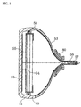
A color picture tube has, as shown in Fig. 1, a structure including an
envelope constructed by a panel 52 and a funnel 53 joined to the panel 52.
In the periphery of the panel 52, a side wall 51 is formed. A phosphor
screen 54 having three colors of R, G, and B is formed on the inner face of
the panel effective portion. A shadow mask 55 in which a number of
electron beam-passing apertures are formed is disposed so as to face the
phosphor screen 54. The funnel 53 has a neck 56 in which an electron gun
57 for emitting three electron beams is disposed. By deflecting the three
electron beams by a magnetic field generated by a deflection yoke 80
attached on the outside of the funnel 53, and by horizontally and vertically
scanning the phosphor screen 54 via the shadow mask 55, a color image is
displayed.
From the viewpoint of a smaller amount of entering external light and
good looking, the panel of a recent color picture tube is being flattened and
the shadow mask 55 is being accordingly flattened. When the shadow
mask 55 is flattened, the plane of the shadow mask 55 cannot be maintained
only by supporting the body of the shadow mask 55 by a frame 58. When
the shadow mask 55 is simply supported only by the frame 58, the shadow
mask 55 easily vibrates by external vibration, so that an adverse influence
is exerted on a display image of the color picture tube. Consequently, the
shadow mask 55 is stretched across the frame 58 in a state where a tensile
force is applied thereto.
In a doming phenomenon that the surface of the shadow mask 55 is
thermally deformed by collision of electron beams with the shadow mask 55,
when the shadow mask 55 is flattened, a displacement amount of the
electron beam becomes large especially around both the left and right edge
faces of the screen. In order to absorb the thermal expansion caused by the
collision of electron beams, a practically maximum tension close to the
elastic limit is applied to the shadow mask 55.
In order to display an accurate color image on the phosphor screen 54
in such a color picture tube, it is necessary to hold the shadow mask 55 in a
predetermined alignment relationship to three-color phosphor layers
constructing the phosphor screen 54. One of the factors that deteriorate
the alignment relationship between the shadow mask 55 and the phosphor
screen 54 is vibration of the shadow mask 55. Although a tensile force is
applied to the shadow mask 55 as described above, it is difficult to
completely suppress the vibration of the shadow mask 55 only by the tensile
force. The vibration of the shadow mask 55 occurs when external vibration
or impact (for example, the vibration of a loudspeaker disposed on a side of
the panel 52) is transmitted from the panel 52 via an elastic support
member 59 and the frame 58 to the shadow mask 55. When the shadow
mask 55 vibrates, the distance between the shadow mask 55 and the
phosphor screen 54 changes, and thereby a landing displacement of the
electron beam occurs. It is consequently desired that the vibration of the
shadow mask 55 be attenuated as much as possible in a short time.
In order to suppress the vibration of the shadow mask 55, it is
necessary to suppress the vibration of the shadow mask 55 itself and the
vibration of the frame 58.
As a method of suppressing the vibration of the shadow mask 55 itself,
a case where a damper is provided on an edge face of the shadow mask 55
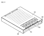
has been reported. Fig. 2 shows an example of the damper. This damper
61 has a structure obtained by bending the ends of a wire. The damper 61
is provided by passing the bent portions into openings 62 in the shadow
mask 55. The size of the opening 62 in the shadow mask 55 is set so that
the damper 61 can freely vibrate. When the shadow mask 55 vibrates, a
part of the energy for vibrating the shadow mask 55 is used to vibrate the
damper 61, so that the vibration of the shadow mask 55 is attenuated.
Even the structure in which such dampers 61 are provided is insufficient to
demonstrate a vibration attenuating effect over the entire shadow mask 55.
On the other hand, in order to suppress the vibration of the frame 58,
it is necessary to add a function such that the vibration can be absorbed by
converting the vibration energy of the frame 58 to, for example, thermal
energy (hereinbelow, called a damper function). As is disclosed in
Japanese Unexamined Patent Publication No. 9-293459, a conventional
method in which a sliding portion is provided with the elastic support
member 59 itself so as to suppress the vibration of the frame 58 by the
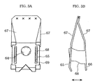
generated friction has been reported. Figs. 3A and 3B show the structure
of the elastic support member disclosed in Japanese Unexamined Patent
Publication No. 9-293459. Fig. 3A is a front view and Fig. 3B is a side view.
The structure has a matching portion 65 having a matching opening 64 to
be matched to a stud pin 63, a fixed portion 66 to be fixed to the frame 58,
and connecting portions 67 for connecting the matching portion 65 and the
fixed portion 66. The connecting portions 67 are joined together by welding
in their mid-portions so as to form a V shape. The fixed portion 66 has a
blade 68 that is inserted into an opening 69 formed in the matching portion
65. When the elastic support member expands and contracts in the
directions indicated by the two-headed arrow as the frame vibrates, the
blade 68 slides in the opening 69, thereby obtaining a damper function.
However, such an elastic support member has a complicated structure and
is not easily produced. Due to a problem of a high cost, it is difficult to
actually adopt the elastic support member.
In addition, the shadow mask 55 has to be attached and detached a
plurality of times during a process of forming the phosphor screen 54 by a
photo printing method using the shadow mask 55 as a photo mask.
Consequently, the elastic support member 59 for holding the frame 58
across which the shadow mask 55 is stretched in a state where a tensile
force is applied thereto has to be easily attached and detached in the same
position with excellent reproducibility.
Further, in addition to the suppression of the vibration, the
elastic
support member 59 is required to have the following characteristics:
Doming characteristic (phenomenon) of (1) is a phenomenon such that
the temperature of the shadow mask 55 rises due to the collision of electron
beams as described above, creating a temperature difference between the
shadow mask 55 and the panel 52 (usually made of glass), and therefore the
predetermined alignment relationship deteriorates due to a thermal
expansion coefficient difference between the material of the shadow mask 55
and that of the panel 52. Low/high temperature characteristic is similar to
doming characteristic and is a phenomenon such that a positional alignment
relationship between the shadow mask 55 and the panel is displaced due to
the temperature difference between the shadow mask 55 and the panel 52
caused by the ambient temperature of the panel 52. Both of the
characteristics are phenomena that the positional alignment relationship
between the shadow mask 55 and the panel 52 is displaced due to the
temperature difference between them. The phenomena cause a color shift
and color unevenness. The displacements cannot be completely
compensated even if a tensile force is applied to the shadow mask 55.
When the shadow mask 55 expands relatively, the displacements between
the shadow mask 55 and the inner face of the panel 52 on which the
phosphor screen 54 is formed has to be compensated by shortening the
distance between the shadow mask 55 and the inner face of the panel 5.
On the contrary, when the panel 52 expands, it is necessary to widen the
distance between the shadow mask 55 and the panel 52. In this manner,
the elastic support member 59 has to have the function of displacing the
position of the shadow mask 55 in accordance with the temperature
difference between the panel 52 and the shadow mask 55.
At the time of carrying the color picture tube, there is a case such that
the color picture tube is subjected to an impact that cannot be imagined in a
normal use state due to an unexpected event (such as collapse of a cargo).
When the shadow mask 55 is displaced due to plastic deformation of the
elastic support member 59 or buckling of the matching portion by the
impact, the positional alignment relationship between the shadow mask 55
and the panel 52 is displaced. The elastic support member 59 therefore has
to be strong enough not to cause a displacement in the shadow mask 55
even when a specific impact (acceleration) is applied.
The structure including the frame, the shadow mask, and the elastic
support member (hereinbelow, called a frame structure) is desired to have
overall excellent characteristics with respect to the suppression of the
vibration of the shadow mask, doming and low/high temperature
characteristics and impact resistance.
An example of the conventional frame structure will be described
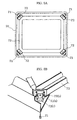
hereinbelow. Fig. 4A is an entire view showing a state where a frame 58 is
disposed in the panel 62 with strip-shaped elastic support members 59. Fig.
4B is an enlarged view of the strip-shaped elastic support member 59. The
strip-shaped elastic support member 59 has a catching portion 60(a) to be
caught by a stud pin 63 of the panel 62, a fixed portion 60(b) to be fixed to
the frame, and a connecting portion 60(c) for connecting the catching portion
60(a) and the fixed portion 60(b). Such a strip-shaped elastic support
member is called a TCM type and has a characteristic of excellent impact
resistance. As a countermeasure against doming and low/high
temperature characteristics, the elastic support member has a bimetallic
structure made of two kinds of materials α (hatched portion) and β
(not-hatched portion) having different thermal expansion coefficients. The
bimetallic effect of the elastic support member 59 is not, however, displayed
unless the temperature of the elastic support member 59 itself changes.
Therefore, there is a problem of a slow response to a change in environment
or a sudden rise in temperature of the shadow mask. Since the
temperature change amount of the elastic support member 59 is small, a
large correction amount cannot be set. Consequently, there is another
problem that a material of the shadow mask having a thermal expansion
coefficient largely different from that of the material of the panel cannot be
used.
In the frame structure, since corners 74 of the frame 58 are not
supported, vibration easily occurs. Moreover, since the elastic support
member of the TCM type has no damper effect, once vibration occurs, it is
not attenuated easily. As a result, the shadow mask also vibrates, thereby
causing a problem that an adverse influence such as a color shift is exerted
on the picture quality.
Fig. 5A shows a frame structure of another conventional technique.
As shown in Fig. 5, stud pins 71 are provided on the inner walls at the
opposite corners of a
panel 70. Each of
elastic support members 72 has a
catching portion 72(a) to be caught by the
stud pin 71, a fixed portion 72(b)
fixed to a frame, and a V-shaped connecting portion 72(c) for connecting the
catching portion 72(a) and the fixed portion 72(b). The connecting portion
72(c) is attached to the phosphor screen side. However, the configuration
has the following problems.
DISCLOSURE OF THE INVENTION
The present invention is intended to solve the conventional problems
mentioned above and provide a color picture tube that is resistant to
external vibration and is excellent in terms of doming and low/high
temperature characteristics and impact resistance, and has a suitable
configuration for easy assembling, and an image display apparatus using
the color picture tube.
The first aspect of the present invention is a cathode ray tube
comprising, at least, a panel having a phosphor screen formed thereon, a
shadow mask having a plurality of electron beam-passing portions, and a
frame across which the shadow mask is stretched in a state where a tensile
force is applied thereto, the frame being securely attached to the panel by an
elastic support member while the phosphor screen is opposed to the shadow
mask, wherein the elastic support member is located substantially in the
middle portion of a frame portion and the shadow mask is configured such
that the tension in the middle portion of the shadow mask is larger than the
tension at the edge portions of the shadow mask.
In the configuration described above, since the elastic support member
is located substantially in the middle portion of the frame portion, the
assembly and frame support may be improved, and since the tension in the
middle portion of the shadow mask is larger than the tension at the edge
portions of the shadow mask, the vibration attenuating effect of the elastic
support member may be found not only at the edge portions of the shadow
mask but also at the middle portion of the shadow mask.
The second aspect of the present invention is a cathode ray tube
comprising, at least, a panel having a phosphor screen formed thereon, a
shadow mask having a plurality of electron beam-passing portions, and a
frame across which the shadow mask is stretched in a state where a tensile
force is applied thereto, the frame being securely attached to the panel by an
elastic support member while the phosphor screen is opposed to the shadow
mask, wherein the elastic support member is fixed to an elastic support
member-holding plate located substantially in the middle of the frame
portion and the shadow mask is configured such that the tension in the
middle portion of the shadow mask is larger than the tension at the edge
portions of the shadow mask.
In the configuration described above, since the elastic support member
is fixed to the elastic support member-holding plate located substantially in
the middle of each frame portion, the elastic support members are located in
the same plane by adjusting the extension direction of the elastic support
member-holding plate even when the frame portions are not in the same
plane, and therefore the effects of the first aspect of the present invention
are demonstrated further.
In these first and second aspects of the present invention described
above, the elastic support member desirably comprises a fixed portion to be
fixed to the frame, a matching portion to be matched to a stud pin provided
on the inside of the panel side wall, and a connecting portion for connecting
the matching portion and the fixed portion. The connecting portion
preferably has an approximately V-shaped configuration. With this
configuration, better doming and low/high temperature characteristics may
be obtained.
In this configuration, the fixed portion of the elastic support member
preferably has an area of at least 5 cm2. This is because when the area of
the fixed portion is made large, a force applied to the frame is dispersed, and
this prevents the tension distribution pattern of the shadow mask from
varying due to the frame deformation. To increase the effect described
above, the ratio of the area of the fixed portion of the elastic support
member to the area of the frame portion to which the elastic support
member is fixed is preferably at least greater than 1/25.
Furthermore, the elastic support member desirably includes a
vibration suppressing structure, because the vibration of the frame is
transmitted to the shadow mask even when the vibration of the shadow
mask is attenuated unless the vibration of the frame is attenuated.
The spring constant of the elastic support member may be altered
relatively easily without changing the size of the elastic support member by
forming an opening in the connecting portion of the elastic support member
and adjusting the size of the opening.
The force applied to the frame portion by the elastic support member is
preferably in the range of 1 kgf to 8 kgf and the spring constant of the
elastic support member is preferably in the range of 0.1 kgf/mm to 2.5
kgf/mm.
The stretched shadow mask is provided with a damper for attenuating
the vibration and has a tension distribution such that the tension is largest
in the middle portion of the shadow mask and decreases gradually toward
the edge portions to ensure that the vibration may be attenuated in the
entire shadow mask. In order to extend the attenuating effect of the
damper to the entire shadow mask, it is preferable that the tension
distribution satisfy the relationships T1 ≥ T2 ≥ T3 and T1 ≥ 1.1 × T3, where
the tension of the shadow mask middle portion is T1, the tension of the
shadow mask edge portions is T3, and the tension of the intermediate
portions between the middle and the edge portions is T2.
Preferably, the damper has a structure that is freely movable with no
portion thereof fixed to the shadow mask in order to improve the
attenuating effect.
Specifically, the damper is preferably so constructed as to be inserted
into an opening formed in the shadow mask and is preferably a wire-like
member or a ring-like member.
As the material for the shadow mask, Fe-Ni alloy is preferable since its
creeping rate is small even when heated to higher temperatures.
The third aspect of the present invention is a cathode ray tube
comprising, at least, a panel having a phosphor screen formed thereon, a
mask having a plurality of electron beam-passing portions, and a frame on
which the mask is held, the frame being securely attached to the panel by a
plurality of elastic support members while the phosphor screen is opposed to
the mask, wherein the plurality of elastic support members are such that at
least two elastic support members having substantially different spring
constants are combined.
In the composition described above, when the plurality of elastic
support members are such that at least two elastic support members having
substantially different spring constants are combined, single vibration mode,
in which the vibration is easily suppressed, predominates, and therefore the
vibration of the frame may be suppressed.
In this third aspect of the present invention described above, desirably,
each of the elastic support members is located substantially in the middle of
a frame portion to suppress the vibration of the mask.
To obtain better doming and low/high temperature characteristics,
desirably, the elastic support member comprises a fixed portion to be fixed
to the frame, a matching portion to be matched to a stud pin provided on the
inside of the panel side wall, and a connecting portion for connecting the
matching portion and the fixed portion. The connecting portion preferably
has an approximately V-shaped configuration.
Of the elastic support members, opposing elastic support members
desirably have the same spring constant in order to increase the intensity of
single vibration further.
The fixed portion of the elastic support member preferably has an area
of at least 5 cm2. This is because when the area of the fixed portion is
made large, the force applied to the frame is dispersed, and this prevents
the tension distribution pattern of the shadow mask from varying due to the
frame deformation. To increase this effect described above, the ratio of the
area of the fixed portion of the elastic support member to the area of the
frame portion to which the elastic support member is fixed is preferably at
least greater than 1/25.
The elastic support member desirably includes a vibration suppressing
structure, because the vibration of the frame is transmitted to the shadow
mask even when the vibration of the shadow mask is attenuated unless the
vibration of the frame is attenuated.
The spring constant of the elastic support member may be altered
relatively easily without changing the size of the elastic support member by
forming an opening in the connecting portion of the elastic support member
and adjusting the size of the opening.
The force applied to the frame portion by the elastic support member is
preferably in the range of 1 kgf to 8 kgf and the spring constant of the
elastic support member is preferably in the range of 0.1 kgf/mm to 2.5
kgf/mm.
Preferably, the mask is stretched across the frame in a state where a
tensile force is applied thereto, and more preferably, the tension in the
middle portion is larger than the tension at the edge portions in the tension
distribution of the mask. The reason for this is that the stretched shadow
mask is provided with a damper for attenuating the vibration and has the
tension distribution in which the tension is largest in the middle portion of
the shadow mask and decreases gradually toward the edge portions to
ensure that the vibration may be attenuated in the entire shadow mask.
In order to extend the attenuating effect of the damper to the entire shadow
mask, it is more preferable that the tension distribution satisfy the
relationships T1 ≥ T2 ≥ T3 and T1 ≥ 1.1 × T3, where the tension of the
shadow mask middle portion is T1, the tension of the shadow mask edge
portion is T3, and the tension of the intermediate portions between the
middle and the edge portions is T2.
Preferably, the damper has a structure which is freely movable with no
portion thereof fixed to the shadow mask in order to increase the
attenuating effect.
Specifically, the damper is preferably so constructed as to be inserted
into an opening formed in the shadow mask and is preferably a wire-like
member or a ring-like member.
As the material for the shadow mask, Fe-Ni alloy is preferable since its
creeping rate is small even when heated to higher temperatures.
Furthermore, the first, second, and third aspects of the present
invention described above may be applied not only to the foregoing cathode
ray tube but also to a general image display apparatus such as a television
set which includes an electron beam controlling circuit, a cabinet, and the
like in addition to the cathode ray tube.
BRIEF DESCRIPTION OF THE DRAWINGS
Fig. 1 is a cross sectional view showing a color picture tube.
Fig. 2 is a perspective view showing a shadow mask in which a damper
of a conventional color picture tube is provided.
Figs. 3A and B are views showing a conventional elastic support
member provided with a damper function. Fig. 3A is a front view thereof
and Fig. 3B is a side view thereof.
Figs. 4A and B are views showing the structure of a conventional color
picture tube, and Fig. 4A is a front view thereof and Fig. 4B is an enlarged
perspective view thereof.
Figs. 5A and B are views showing the structure of a conventional color
picture tube. Fig. 5A is a front view thereof and Fig. 5B is an enlarged
perspective view thereof.
Fig. 6 is a perspective view illustrating Embodiment 1.
Fig. 7 is a perspective view showing an elastic support member used in
Embodiment 1.
Fig. 8 is a phase diagram showing one example of a tension
distribution of a shadow mask. Fig. 8A is a view showing an A-type
distribution, and Fig. 8B is a view showing an M-type distribution.
Fig. 9 is a phase diagram showing changes in the tension distribution
of a shadow mask.
Fig. 10 is a perspective view showing one form of the dampers.
Fig. 11 is a perspective view showing another form of the dampers.
Fig. 12 is a graph showing the relationship between T1/T3 and
vibration suppressing time.
Fig. 13 is a view showing a variation of the elastic support member.
Fig. 13A is a perspective view thereof, and Fig. 13B is a cross sectional view
thereof.
Fig. 14 is a view showing another variation of the elastic support
member. Fig. 14A is a perspective view thereof, and Fig. 14B is a cross
sectional view thereof.
Fig. 15 is a perspective view showing an elastic support member used
in Embodiment 2.
Fig. 16 is a perspective view showing an elastic support member used
in Embodiment 3.
Fig. 17 is a phase diagram showing the condition of the attenuated
vibration of a frame in Embodiment 3.
Fig. 18 is phase diagram showing the result of analysis of the vibration
modes of a frame.
Fig. 19 is a perspective view showing the movement of an elastic
support member at the time of torsional vibration mode.
Fig. 20 is a cross sectional view showing the movement of an elastic
support member at the time of single vibration mode.
Fig. 21 is a perspective view showing Embodiment 4.
BEST MODE FOR CARRYING OUT THE INVENTION
Embodiments of the present invention will now be explained in details
with reference to the drawings. The shadow mask of the color picture tube
explained hereinbelow is a flat-faced mask, and the constructioin of the color
picture tube having been explained with reference to Fig. 1 also applies to
the following embodiments.
Embodiment 1
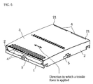
Fig. 6 is a perspective view of frame portions according to Embodiment
1 of the present invention. In Fig. 6, reference numeral 1 denotes left and
right frame portions, and reference numeral 2 upper and lower frame
portions wherein a shadow mask 3 is stretched in a state where a tensile
force is applied in vertical directions (as indicated by the two-headed arrow).
Wire-like dampers 4 for attenuating the vibration of the shadow mask are
provided on left and right edge surface portions of the shadow mask 3. In
the embodiment, a 29-inch frame is used and the shadow mask 3 has a
tension distribution set to 4.3 kgf/mm2 for the middle portion, 3.4 kgf/mm2
for the left and right edge surface portions, and 3.6 kgf/mm2 for
intermediate portions between the middle portion and the left and right
edge surface portions. 36% Ni-Fe alloy was employed for manufacturing
the shadow mask 3.
Elastic support members 5 for attaching the frame to the panel are
located substantially in the middle portions of the frame portions 1,2 in view
of assembly and support of the frame portions 1, 2 {on-axial SP (spring)
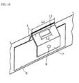
structure}. Fig. 7 illustrates an enlarged view of the elastic support
member 5 employed in the embodiment. The elastic support member 5
comprises a fixed portion 6 to be fixed to the frame portion, a matching
portion 7 to be matched to a stud pin provided on the inside of the panel side
wall, and a V-shaped connecting portion 8 for connecting the fixed portion 6
and the matching portion 7, the connecting portion 8 having an opening 13.
It is possible to determine a spring constant for the elastic support member
5 by varying the size of the opening 13 (particularly its length L) and the
plate thickness of the connecting portion 8, wherein L is set to be 25 mm,
the plate thickness 0.6 mm and the spring constant 1.2 kgf/mm in the
embodiment.
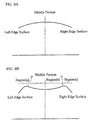
For demonstrating the vibration attenuating effect over the entire
shadow mask 3, it is desirable that the tension distribution be such that the
tension in the middle portion of the shadow mask is largest while it becomes
gradually lower toward the edge portions (hereinafter referred to as "A-type
distribution") as illustrated in Fig. 8A. This is because in a distribution
such that a tension peak is obtained somewhere other than the middle
portion (hereinafter referred to as "M-type distribution") as is shown in Fig.
8B, the vibration attenuating effect owing to dampers do not cover the
region (b) of the middle portion while the vibration attenuating effect are
recognized on the regions (a) extending from the edge portions up to where
the peak tension is obtained. This is due to the fact that spot P where the
peak tension is achieved vibrates as being a node so that the extension of
the vibration attenuating effect of the dampers are suppressed at the
tension peak. It should be noted that the vibration attenuating effect is
prevented from expanding due to similar reasons even when the shadow
mask includes wrinkles or irregularities in tension.
[Experiments]
The above-described shadow mask frame was assembled into a CRT
and evaluated. The results are indicated in Table 1. It should be noted
that this Table 1 also includes the results obtained by using strip plate-like
elastic support members of the prior art (hereinafter referred to as "TCM
type") and those illustrated in
Embodiment 2.
| Results on Characteristics Evaluation (29-inch) |
| Item | Targets | Embodiment | 1 | Embodiment 2 | Prior Art (TCM type) |
| | | Results | Assessment- | Results | Assessment | Results | Assessment |
| Vibration tapping test *1 | Color shift continuity 2 sec or less | 1.5 sec | Good | 1.6 sec | Good | | 1 sec | Good |
| Loudspeaker test *2 | No color shift | No color shift | Good | No color shift | Good | No color shift | Good |
| Low/high temperature Characteristic | 1 µm/°C or lower | 0.9 µm/°C | Good | | 1 µm/°C | Good | 1.5 µm/°C | Poor |
| Overall doming | 30 µm or less | 20-30 µm | Good | 28 µm | Good | 40 µm | Poor |
| Drop (impact-resistance) test (35 G: 40 ms) | Displacement amount of frame position 20 µm or less | 15-20 µm | Good | 20 µm | Good | 100 µm or greater | Poor |
As it is evident from Table 1, the targets in all items were attained,
and the frame proved to be strong against external vibration and to be
superior in terms of doming and low/high temperature characteristics as
well as impact resistance. The frame may also be easily assembled since it
is of on-axial SP structure, and a fraction defective during the process of
attaching the frame to the panel (including photolithograph process) was
remarkably decreased to be not more than 1/10.
The conventional TCM type elastic support member was not sufficient
in terms of doming characteristic, low/high temperature characteristic, and
impact resistance. Therefore, an elastic support member having the above
-mentioned construction (hereinafter referred to as "mechanical type") is
desirable.
[Supplementary remarks]
(1) While the area of the fixed portion 6 of the elastic support member
5 in which is fixed to the frame as employed in Embodiment 1 was set to be
10 cm2, but the present invention is not limited to this value. It should,
however, be noted that this area be desirably as large as possible, and
preferably 5 cm2 at the minimum. This is because a small area of the fixed
portions 6 may result in deformation of the frame since the force applied on
the frame by the elastic support member 5 focuses thereon and thereby
changes the pattern of the tension distribution of the shadow mask 3 as
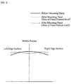
illustrated in Fig. 9. As has been explained, changes in the tension
distribution pattern are not preferable since they create regions in which
the vibration of the shadow mask is hard to be attenuated. For these
reasons, the area of the fixed portion 6 of the elastic support member 5 in
which is fixed to the frame is desirably as large as possible, and preferably 5
cm2 at the minimum.
(2) While it is possible to prevent the vibration of the shadow mask 3
by setting the area of the fixed portion 6 of the elastic support member 5 in
which is fixed to the frame to be larger than 5 cm2, as described above, in
Embodiment 1 (wherein the panel size is of 29-inch), this method is also
applicable to panels of different sizes. It has been confirmed through
experiments that similar effects may be obtained by setting a ratio (A1/A2)
of the area (A1 cm2) of the fixed portion 6 of the elastic support member 5 to
the area (A2 cm2) of the frame portion to which the elastic support member
5 is fixed to be larger than 1/25.
(3) Although employed in Embodiment 1 is a mechanical type elastic
support member 5 having a spring constant of 1.2 kgf/mm and the force
applied to the frame portion when the frame is disposed in the panel is
approximately 3.5 kgf, the mechanical type elastic support member 5 that
may be applied to the present invention is not limited to this. However, the
force applied to the frame portion is preferably in the range of 1 kgf to 8 kgf.
This is because the disposing condition of the frame to the mask is unstable
when the force is less than 1 kgf while the frame is deformed when the force
exceeds 8 kgf, and the tension distribution of the shadow mask 3 changes
into M-type whereby the vibration becomes hard to be attenuated.
It has thus been confirmed through experiments that it is preferable to
set the spring constant of the mechanical type elastic support member 5 to
be in the range of 0.1 kgf/mm to 2.5 kgf/mm for realizing the
above-described disposing condition. Because a realizable maximum limit
of the clearance between the frame and the panel is 20 mm (and smaller
when the panel size is smaller), the spring constant needs to be not less
than 0.1 kgf/mm for realizing the above-mentioned force for disposing. On
the other hand, when the spring constant exceeds 2.5 kgf/mm, the spring
constant rigidity becomes large enough not to cause the deformation,
thereby remarkably worsening the assembling characteristics, and even
when the same amount of force is applied, the deformation occurs only in a
small amount. As a result, good doming characteristic and low/high
temperature characteristic remarkably deteriorate.
(4) While each damper 4 provided on the left and right edge surface
portions of the shadow mask 3 is constructed such that a wire-like member
is partially bent to be inserted into the opening 21 formed in the shadow
mask 3 in Embodiment 1, the damper 4 applicable to the present invention
is not limited to this type, and it may also be a ring-like member 9
illustrated in Fig. 10. It may alternatively be a damper 11 such that one
portion thereof contacts an edge surface 12 of the shadow mask while
another portion is fixedly attached to a frame 10 as illustrated in Fig. 11.
(5) The material for the shadow mask desirably has a small thermal
creeping rate in a high temperature condition in a state where a tension is
applied thereto. In a CRT manufacturing process, it is necessary to
perform a plurality of high temperature heat treatment processes such as a
heat process for easing the stress generated at the time of stretching the
shadow mask, a fritting process of forming an exterior tube, and the like.
In a construction in which the shadow mask with a tension applied is
stretched across the frame, it is not preferable that the thermal creeping
take place in the shadow mask during the heat treatment processes because
phenomena such as a decrease in tension, a change in the tension
distribution, wrinkles in the shadow mask, and the like occur. In order to
absorb the thermal creeping, it is required to apply quite a large tension to
the shadow mask. This involves an increase in the frame strength, thereby
leading to other problems such as an increase in frame weight, more
complicated and expensive stretching equipment, complications in the
process, and the like. Thus, it is desirable to select, as the material for the
shadow mask, a material such as Ni-Fe alloy (Invar material) as employed
in Embodiment 1 or the like that exhibits a small thermal creeping rate in a
high temperature condition in a state where a tension is applied thereto.
(6) For expanding the vibration attenuating effect of the dampers over
the entire shadow mask, it is preferable to set the tension distribution of the
shadow mask so as to satisfy the relationships T1 ≥ T2 ≥ T3 and T1 ≥ 1.1 ×
T3, where T1 is a tension at the middle portion of the shadow mask, T3 a
tension at the edge portions, and T2 a tension of the intermediate portions
between the middle portion and the edge portions. This is due to the fact
that the vibration suppressing time becomes longer when the relationship
T1 < 1.1 × T3 is satisfied as illustrated in Fig. 12. Note that the vibration
suppressing time means a time required for attenuating amplitude of
vibration to 1/10 or lower.
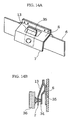
(7) It is desirable that the elastic support member comprises a
vibration suppressing structure that is achieved through means such as
welding a sliding member 33 having a cylindrical cross-sectional shape to
the fixed portion so as to slide to a tip end of the stud pin 34 as illustrated in
Figs. 13A and B, welding a strip-like sliding member 35 to the fixed portion
6 so as to slide to the tip end of the stud pin 34 as illustrated in Fig. 14, or
the like. This is due to the fact that the vibration is transmitted to the
shadow mask even when the vibration of the frame is attenuated unless the
vibration of frame is attenuated.
Embodiment 2
Fig. 15 is a perspective view of frame portions according to
Embodiment 2 of the present invention. It should be noted that members
having functions identical to those of Embodiment 1 are denoted by the
same reference numerals, and therefore the explanations are omitted.
Embodiment 2 is of similar construction as that of Embodiment 1
expect that among the elastic support members 5 for attaching the frame to
the panel, those disposed corresponding to the upper and lower frame
portions 2 are fixed to elastic support member-holding plates 20 located
substantially in the middle portions of the upper and lower frame portions 2
(the area of each elastic support member-holding plate 20 fixed to the upper
and lower frame portions 2 is 15 cm2), and that the shadow mask 3 has a
tension distribution set to 4.0 kgf/mm2 for the middle portion, 3.2 kgf/mm2
for the left and right edge surface portions, and 3.5 kgf/mm2 for the
intermediate portions between the middle portion and the left and right
edge surface portions.
[Experiments]
The above-described shadow mask frame was assembled into a CRT
and evaluated. The results are indicated in the above Table 1. Similarly
to Embodiment 1, the targets in all items were attained and the frame
proved to be strong against external vibration and to be superior in terms of
doming and low/high temperature characteristics as well as impact
resistance. The frame may also be easily assembled since it is of on-axial
SP structure, and a fraction defective during the process of attaching the
frame to the panel (including photolithograph process) was remarkably
decreased to be not more than 1/10.
[Supplementary remarks]
(1) to (7) of Embodiment 1 also applies to Embodiment 2, and therefore
the explanations are omitted.
Embodiment 3
Fig. 16 is a perspective view of an elastic support member according to
Embodiment 3 of the present invention. It should be noted that members
having functions identical to those of Embodiment 1 are denoted by the
same reference numerals, and therefore the explanations are omitted.
Embodiment 3 is of similar construction as that of Embodiment 1
expect that the elastic support members disposed to the upper and lower
frame portions 2 have spring constants of 0.2 kgf/mm (L1: 50 mm, L2: 25
mm, t:0.3 mm) and that the elastic support members disposed to the left
and right frame portions 1 have spring constants of 1.2 kgf/mm (L1: 50 mm,
L2: 25 mm, t:0.6 mm). Note that the forces applied to the frame portions
were 1.2 kgf and 3.5 kgf, respectively, when the frame was disposed in the
panel by using these elastic support members.
[Experiments]
A frame structure as the one described above was assembled into a
CRT and evaluated. The results are indicated in Table 2.
| Results on Characteristics Evaluation (29-inch) |
| Item | Target | Embodiment | 3 | Prior Art (TCM type) |
| | | Results | Assessment | Results | Assessment |
| Vibration tapping test *1 | Color shift 2 sec or less | 0.5 sec | Good | 1.5sec | Good |
| Loudspeaker test *2 | No color shift | No color shift | Good | No color shift | Good |
| Low/high temperature characteristic | 1 µm/°C or lower | 0.9 µm/°C | Good | 1.5 µm/°C | Poor |
| Overall doming | 30 µm or less | 20-30 µm | Good | 40 µm | Poor |
| Drop (impact resistance)test (35 G:40 ms) | Displacement amount of frame position 20µm or less | 15-20 µm | Good | 100µm or greater | Poor |
As it is evident from Table 2, the targets in all items were attained,
and the frame proved to be strong against external vibration and to be
superior in terms of doming and low/high temperature characteristics as
well as impact resistance. Particularly in view of vibration, the vibration of
the frame was suppressed in a time of 0.5 seconds or less even when such an
impact as to have an acceleration of 3G was applied to the panel as
illustrated in Fig. 17B. The frame may also be easily assembled since it is
of on-axial SP structure, and a fraction defective during the process of
attaching the frame to the panel (including photolithograph process) was
remarkably decreased to be not more than 1/10.
On the other hand, the conventional TCM type frame was not
sufficient in terms of doming characteristic, low/high temperature
characteristic and impact resistance. Therefore, the above mechanical type
is desirable.
In this manner, the elastic support member of
Embodiment 3 is
effective in suppressing the vibration of the frame, and the principle will
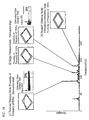
now be explained. In analyzing the vibration modes of the frame structure
in which the mechanical type elastic support members are located
substantially in the middle portions of the frame portions, it was found that
three modes existed as illustrated in Fig. 18 (the results of analysis
illustrated in Fig. 18 are those of a 29-inch panel. When the size of the
panel is varied, the generated frequency of the modes changes though the
mode shapes are the same).
The conditions of the attenuated vibration were measured as follows
(referred to as "loudspeaker single tone test"): a loudspeaker was set onto
the panel surface, a vibration having a frequency only enough to generate
the respective vibration modes was applied thereto, and then the
loudspeaker was turned off. It was found that the vibration could be
hardly attenuated in the torsional vibration mode and the vibration
continued. In the single vibration mode, the vibration could be attenuated
in a time of not more than 1/10 of that required for the torsional vibration
mode. In the parallel vibration mode, the vibration was attenuated as
quick as measuring was nearly impossible.
The reasons for this may be attributed to the movements of the elastic
support members. In the case of the torsional vibration mode, each of the
elastic support members so shook about the stud pins 85 as to cause torsion
to a matching portion 86(a) or a connecting portion 86(c) of the elastic
support member as illustrated in Fig. 19. In such movements, because the
elastic support member has no damper effect, the vibration of the frame
continues without being suppressed. In the single vibration mode, the
elastic support members, serving as a fulcrum, show the same movements
as those of the torsional mode while the other elastic support members
perform expanding and contracting movements as illustrated in Fig. 20
(expanding and contacting movements are performed in the directions
indicated by the two-headed arrow). At this time, a matching opening 87
and the stud pin 85 of the elastic support member slide slightly with respect
to the stud pin 85 and the matching portion 86(a) of the elastic support
member. The friction caused by the sliding of the matching opening 87 and
the stud pin 85 becomes a damper function, thereby serving to suppress the
vibration of the frame. In the parallel vibration mode, all the elastic
support members perform the expanding and contracting movements,
thereby creating quite a large damper function so that the vibration of the
frame is instantly suppressed.
All the elastic support members disposed to the left and right frame
portions and the upper and lower frame portions are identical (in shape, in
spring constant, and the like) in most cases. If this is the case, the
vibration of the frame is mainly of the torsional mode and the single
vibration mode or the parallel vibration mode hardly occurs. Thus, the
vibration of the frame continues without being suppressed. It was found
that the two vibration modes of the single vibration mode and the parallel
vibration mode could be brought about by employing elastic support
members having different spring constants.
Table 3 illustrates the results of the intensity ratios of the torsional
mode and the single vibration mode were obtained in the case that the
spring constants of the elastic support members disposed to the upper and
lower frame portions were fixed to be 0.2 kgf/mm, and the spring constants
of the elastic support members disposed to the left and right frame portions
were varied in the range of 0.2 kgf/mm to 1.9 kgf/mm.
| Spring constant of the springs disposed to the upper and lower frame portions: 0.2 kgf/mm |
| Spring constant of the springs disposed to the left and right frame portions | Vibration intensity (relative ratio) |
| | Torsional mode | Single vibration mode |
| k:0.2 kgf/mm | 5 | 0 |
| k:1.2 kgf/mm | 3 | 1.7 |
| k:1.5 kgf/mm | 1 | 0.5 |
| k:1.9 kgf/mm | 0.6 | 0.7 |
The intensities as illustrated in Table 3 are the relative values in a case
where the vibration intensity of a measuring system when external
vibration is applied is set to be 1. It can be understood from these results
that the single vibration mode predominates by varying the spring
constants of the elastic support members for the left and right frame
portions and for the upper and lower frame portions.
By varying the spring constants of the elastic support members in the
above manner, a part of the torsional vibration mode can be switched to the
single vibration mode so that the vibration of the frame can be suppressed.
An effective means to increase the intensity of the single vibration mode is
that the opposing elastic support members disposed to the upper and lower
frame portions have the same spring constant and the opposing elastic
support members disposed to the left and right frame portions have the
same spring constant.
The spring constant of each elastic support member can be relatively
easily varied without varying the size of the elastic support member by
forming an opening in the connecting portion of the elastic support member
and adjusting the size of the opening.
[Supplementary remarks]
(1) to (7) of Embodiment 1 also applies to Embodiment 3, and therefore
the explanations are omitted.
(8) In Embodiment 3, the elastic support members are directly
disposed to the frame. However, the invention is not limited thereto. As
shown in Embodiment 2, the elastic support member may be disposed to the
frame with the elastic support member-holding plate interposed
therebetween.
(9) According to Embodiment 3 of the present invention, each of the
elastic support members is located substantially in the middle of a frame
portion. While the invention is not limited thereto, it should be noted that
it is preferable that the elastic support member is located substantially in
the middle of the frame portion in order to suppress the vibration of the
mask, more effectively.
(10) In order to increase the intensity of the single vibration mode, it is
desired that of the elastic support members, opposing elastic support
member have the same spring constant.
(11) It is preferable that the mask is stretched across the frame in a
state where a tensile force (tension) is applied thereto. In this case, it is
more preferable that the tension distribution of the mask be such that the
tension in the middle is larger than the tension at the edge portions. This
is because in the shadow mask in which a damper for attenuating the
vibration is provided, the vibration of the entire mask can be certainly
attenuated by providing a tension distribution in which the tension is
largest in the middle portion while it becomes gradually lower toward the
edge portions.
(12) The third aspect of the present invention can be applied to a mask
in which a flat-faced mask provided with a plurality of electron
beam-passing apertures are stretched in the vertical/horizontal direction,
and also a mask in which a plurality of thin lines called aperture grills are
stretched in the vertical direction. Incidentally, furthermore, the shadow
mask is not limited to the flat-faced mask, and may be a mask being
stretched so as to have a cylindrical surface.
Embodiment 4
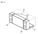
Embodiment 4 of the present invention is a TV set to which the color
picture tube according to Embodiments 1 to 3 is applied. Fig. 21 is a
perspective view showing an outline of Embodiment 4. Reference numeral
25 denotes a color picture tube of the present invention. Reference
numeral 26 denotes a loudspeaker. Reference numeral 27 denotes a circuit
such as an electron beam controling and tuner. With such structure, a flat
TV set in which color shift caused by external vibration is small and
reliability against unexpected accidents at the time of transportation is high
is realized.
Incidentally, the structure of the present invention is not limited to the
TV set, and may be applied to a general image display apparatuses such as
a monitor.
INDUSTRIAL APPLICABILITY
As has been described above, the present invention is advantageous in
that it provides a color picture tube that has a strong resistance to external
vibration, good doming and low/high temperature characteristics, and good
impact resistance and is easy to be assembled. The invention also provides
a flat TV set employing the color picture tube.