EP1223590A2 - Method of manufacturing superconducting cable - Google Patents
Method of manufacturing superconducting cable Download PDFInfo
- Publication number
- EP1223590A2 EP1223590A2 EP02000235A EP02000235A EP1223590A2 EP 1223590 A2 EP1223590 A2 EP 1223590A2 EP 02000235 A EP02000235 A EP 02000235A EP 02000235 A EP02000235 A EP 02000235A EP 1223590 A2 EP1223590 A2 EP 1223590A2
- Authority
- EP
- European Patent Office
- Prior art keywords
- cores
- spacers
- superconducting cable
- cable
- slack
- Prior art date
- Legal status (The legal status is an assumption and is not a legal conclusion. Google has not performed a legal analysis and makes no representation as to the accuracy of the status listed.)
- Granted
Links
Images


Classifications
-
- H—ELECTRICITY
- H01—ELECTRIC ELEMENTS
- H01B—CABLES; CONDUCTORS; INSULATORS; SELECTION OF MATERIALS FOR THEIR CONDUCTIVE, INSULATING OR DIELECTRIC PROPERTIES
- H01B12/00—Superconductive or hyperconductive conductors, cables, or transmission lines
- H01B12/02—Superconductive or hyperconductive conductors, cables, or transmission lines characterised by their form
-
- H—ELECTRICITY
- H01—ELECTRIC ELEMENTS
- H01B—CABLES; CONDUCTORS; INSULATORS; SELECTION OF MATERIALS FOR THEIR CONDUCTIVE, INSULATING OR DIELECTRIC PROPERTIES
- H01B12/00—Superconductive or hyperconductive conductors, cables, or transmission lines
-
- H—ELECTRICITY
- H01—ELECTRIC ELEMENTS
- H01B—CABLES; CONDUCTORS; INSULATORS; SELECTION OF MATERIALS FOR THEIR CONDUCTIVE, INSULATING OR DIELECTRIC PROPERTIES
- H01B13/00—Apparatus or processes specially adapted for manufacturing conductors or cables
- H01B13/02—Stranding-up
-
- Y—GENERAL TAGGING OF NEW TECHNOLOGICAL DEVELOPMENTS; GENERAL TAGGING OF CROSS-SECTIONAL TECHNOLOGIES SPANNING OVER SEVERAL SECTIONS OF THE IPC; TECHNICAL SUBJECTS COVERED BY FORMER USPC CROSS-REFERENCE ART COLLECTIONS [XRACs] AND DIGESTS
- Y02—TECHNOLOGIES OR APPLICATIONS FOR MITIGATION OR ADAPTATION AGAINST CLIMATE CHANGE
- Y02E—REDUCTION OF GREENHOUSE GAS [GHG] EMISSIONS, RELATED TO ENERGY GENERATION, TRANSMISSION OR DISTRIBUTION
- Y02E40/00—Technologies for an efficient electrical power generation, transmission or distribution
- Y02E40/60—Superconducting electric elements or equipment; Power systems integrating superconducting elements or equipment
-
- Y—GENERAL TAGGING OF NEW TECHNOLOGICAL DEVELOPMENTS; GENERAL TAGGING OF CROSS-SECTIONAL TECHNOLOGIES SPANNING OVER SEVERAL SECTIONS OF THE IPC; TECHNICAL SUBJECTS COVERED BY FORMER USPC CROSS-REFERENCE ART COLLECTIONS [XRACs] AND DIGESTS
- Y10—TECHNICAL SUBJECTS COVERED BY FORMER USPC
- Y10T—TECHNICAL SUBJECTS COVERED BY FORMER US CLASSIFICATION
- Y10T29/00—Metal working
- Y10T29/49—Method of mechanical manufacture
- Y10T29/49002—Electrical device making
- Y10T29/49014—Superconductor
Definitions
- the present invention relates to a method of manufacturing a superconducting cable. More particularly, the present invention relates to a method of manufacturing a superconducting cable to ensure contraction allowance of a cable core for cooling.
- a superconducting cable is cooled by a coolant, such as liquid nitrogen in the cable.
- a coolant such as liquid nitrogen in the cable.
- the outermost layer of the cable is at ambient temperature, whereas the inside of the cable remains at about -200°C. Hence, a temperature difference between the inside and outside of the cable is 200°C or more.
- Metal constituting the cooled cable is subjected to a contraction of about 0.3%; more specifically, the cable is subjected to a thermal contraction of about 30 cm every 100 meters.
- a conductor of the superconducting cable is formed by stranding a plurality of cable cores. Both ends of the cable are fixed to an interconnection section or a terminal connection section.
- the technique as described in Japanese Patent Unexamined Publication No. Hei. 09-134620 has hitherto been known as a technique for managing such thermal contraction. Specifically, an intermediate substance having a large thermal contraction rate is provided in the center of three cable cores, and the three cables are stranded with the intermediate substance interposed therebetween. The strands of three cable cores change in diameter by virtue of thermal contraction of the intermediate substance, thereby managing thermal contraction.
- the above-described technique requires use of the intermediate substance having a large thermal contraction rate in addition to the cable cores, thus increasing the number of components.
- An object of the present invention is to provide a method of manufacturing a superconducting cable which can manage thermal contraction without integrating another member with cable cores.
- the present invention achieves the object by temporarily providing a spacer between cable cores so that the cores can be housed in a thermally insulated pipe in a slacked state.
- the present invention provides a method of manufacturing a superconducting cable comprising:
- spacers are interposed between the cores.
- the cores are stranded at intervals corresponding to the thicknesses of the spacers.
- the spacers are removed and the cores are housed in the pipe while slack corresponding to the thicknesses of the spacers is maintained.
- the thicknesses of the spacers are optimized, it is possible to easily manufacture of three cores having sufficient slack to manage the thermal contraction which occurs when the cable is cooled in the thermally insulated pipe.
- the thermally insulated pipe has a structure such that a vacuum thermal insulation layer is formed between an outer pipe and an inner pipe, and the stranded cores are housed in the inner pipe.
- the inner pipe is formed from stainless steel
- the stainless steel plate covers the outer circumferential surfaces of strands of the cores. Joints between metal plates are sequentially welded by means of a welder.
- the spacers are removed before the cable cores are introduced into the welder.
- the inner pipe is formed from copper or aluminum, in some cases metal is extruded to the outer circumferential surface of the cable cores by means of an extruder. In this case, the spacers are removed before the cables are introduced into the extruder.
- Removal of the spacers is performed easily by drawing the spacers from grooves between the stranded cores. For instance, the spacers are drawn sideways of a line and taken up immediately before the cores are introduced into the welder or extruder.
- Preferable material for the spacer is a substance having flexibility and strength across the thickness thereof. More specifically, the spacer material includes fluororesin-based material, vinyl-based material, rubber-based material, paper-based material, and felt-based material.
- a suitable geometry of the spacer is the shape of an elongated tape.
- the thickness of the spacer preferably satisfies the following requirements.
- Requirement (1) is for managing the contraction of cores. Selection between full management of a required amount-of slack or partial management of the same may be determined by design, as required.
- Requirement (2) is for preventing damage to the cores, which would otherwise be caused when the cores come into contact with the interior surface of the thermally insulated pipe at the time of machining of the thermally insulated pipe.
- the inner diameter B of the thermally insulated pipe is preferably set to the minimum value.
- the cable has three cores 2 housed in a thermally insulated pipe 1.
- the thermally insulated pipe 1 is constituted by providing thermal insulation material, such as multi-layer thermal insulation (not shown), between an outer pipe 3 and an inner pipe 4, and evacuating a space defined between the pipes 3, 4.
- the cable cores 2 are stranded with sufficient slack to enable management of thermal contraction.
- the outer and inner pipes 3, 4 are formed into corrugated pipes.
- Each of the cable cores 2 comprises, in order from the center, a former 5, a superconductor 6, an electrical insulation layer 7, and a shield layer 8.
- a protective layer may be provided outside of the shield layer 8.
- the former 5 is hollow.
- the internal space of each former 5 and the space defined between the inner pipe 4 and the cable cores 2 serve as coolant channels.
- oxide superconductors such as a Y-based superconductor or a Bi-based superconductor
- Materials that can be used as the electrical insulation layer 7 include a paper tape soaked with coolant, or a composite paper composed of a paper tape and a plastic tape, and the electrical insulation layer 7 is formed by winding such paper tape. Liquid nitrogen or liquid helium can be utilized for the coolant.
- the cable is manufactured according to a method provided below after manufacture of cable cores.
- Spacers are interposed among the three cores at the time of stranding of the cores as shown in Fig. 2.
- Rectangular slits 11 are formed in a batten plate 10 which is to act as a guide at the time of stranding of cores.
- a tape-like spacer 12 is caused to pass through each of the slits 11.
- the spacers 12 are sandwiched between the cores 2, thereby producing three cores with the side surfaces of the spacers 12 exposed through grooves among the strands.
- the three cores with the spacers are housed in the inner pipe 4.
- the inner pipe is usually produced by covering an outer circumferential surface of the thus-stranded cores 2 with a metal plate 20 (e.g., a stainless plate) and sequentially welding joints in the metal plates 20 with a welder 21.
- the inner pipe is not a corrugated pipe but a linear pipe.
- the inner pipe 4 is introduced into a corrugator 22, where the pipe 4 is corrugated.
- the thus-corrugated pipe 4 is taken up on a drum 23.
- the spacers 12 are removed before the stranded cores is introduced into the welder 21.
- the spacers 12 can be easily removed by being drawn from the grooves defined among the stranded cores. For instance, before the time of introduction of the stranded cores into the welder 21, the ends of the stranded cores have been subjected to terminal treatment for preventing spreading of the cores, and the respective spacers 12 have been drawn from the cores. Since the spacers 12 are sandwiched merely among the cores 2, the spacers 12 can be easily pulled by hand. Preferably, the spacers are drawn sideways of the production line and taken up.
- the three cores can be housed in the corrugated inner pipe 4 with slack corresponding to the thickness of the spacers 12.
- the slack is maintained not only during the process of processing the corrugated inner pipe but by the end of assembly of the cable.
- the present embodiment adopts a core outer diameter D of 39.5 mm; an inner diameter B of 93 mm for a corrugated inner pipe; and a core stranding pitch of 1000 mm.
- a standard inner diameter of the corrugated inner pipe is 95 mm.
- a smallest inner diameter of 93 mm is adopted.
- a required amount of slack A0 is taken as 0.3%, and trial calculation this time takes into consideration full management of the required amount of slack A0.
- a slack of 0.3% is imparted to the cores at the time of manufacture of the corrugated inner pipe.
- a conceivable measure is to maximize a spacer thickness.
- the profile of strands of three cores becomes apt to deformation at the time of manufacture of a cable core.
- constraints on production that is, the outer diameter of a core being sufficient to house the core into the inner pipe; and obviation of a risk of causing a failure to weld the inner pipe at the time of manufacture of the inner pipe or a risk of inflicting damage to cores.
- An amount of design slack A1 is expressed mathematically by Eq. 1, provided that the length of one pitch of cores with spacers is taken as L1 and the length of one pitch of cores without spacers is taken as L2.
- A1 ⁇ (L1/L2)-1 ⁇ 100
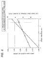
- the thickness "t" of a spacer is determined such that 0.3% ⁇ A1 and the diameter of an enveloping circle circumscribing the three cores with spacers assumes a value of ⁇ 93 mm.
- Lengths L1, L2 can be determined as follows.
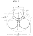
- Fig. 5 is a cross-sectional view of a three-core strand into which cable cores 2, each having a diameter D, are stranded while tape like spacers 12 having a thickness "t" are sandwiched between the cable cores.
- a distance r1 from the center of the enveloping circle circumscribing the three cores having the spacers to the center of each core is determined by Eq. 2.
- r 1 t + D 2 cos 30°
- a distance r2 from the center of the enveloping circle circumscribing the three cores not having spacers (unillustrated) to the center of each core is determined by Eq. 3.
- r 2 D 2 cos 30°
- the length L per pitch of the stranded three cores is expressed by Eq. 4, provided that a distance from the center of the enveloping circle circumscribing the three cores to the center of each core is taken as "r.”
- Core Length (2r ⁇ ) 2 + pitch 2
- L1 and L2 are expressed by Eq. 5 and Eq. 6, respectively.
- L 1 ( t + D ) cos30° ⁇ + pitch 2
- L 2 D cos30° ⁇ + pitch 2
- the diameter of the enveloping circle circumscribing the three cores having spacers is expressed by Eq. 7 provided below. From Equations 1, 5, 6, and 7, there is selected "t" which satisfies 0.3% ⁇ A1 and such that the diameter of the enveloping circle circumscribing the three cores having spacers becomes ⁇ 93 mm. t + D cos 30° + D
- a graph shown in Fig. 6 denotes a relationship between the spacer thickness and the amount of design slack, and a relationship between the spacer thickness and the diameter of an enveloping circle circumscribing the three cores having spacers.
- the example trial calculation has described the case of three cores. Even when the number of cores is less than or greater than three, a spacer thickness is determined on the basis of the same concept and in the same manner.
- cores can be housed in a thermally insulated pipe with sufficient slack for managing thermal contraction, by temporarily interposing spacers between cores.
- a superconducting cable capable of managing thermal contraction without integrating another member with cable cores.
Landscapes
- Engineering & Computer Science (AREA)
- Manufacturing & Machinery (AREA)
- Superconductors And Manufacturing Methods Therefor (AREA)
Abstract
Description
where the amount of required slack A0 is expressed by a rate of thermal contraction of the core ({(the length of one pitch of the core after contraction/the length of one pitch of the core before contraction)-1}100), and the amount of design slackAl is expressed by {(L1/L2)-1}100, provided that the length of one pitch of the cores having the spacers is taken as L1 and the length of one pitch of cores not having spacers is taken as L2; and
where the diameter of the enveloping circle corresponds to the diameter of a circle circumscribing the stranded cores having spacers.
Claims (5)
- A method of manufacturing a superconducting cable comprising:providing spacers in a plurality of cores at the time of stranding of the cores; andremoving the spacers before the stranded cores are housed in a thermally insulated pipe, and housing the cores into the thermally insulated pipe while the strands are held in a slacked state.
- The method of manufacturing a superconducting cable according to claim 1, wherein the thickness of each of the spacers satifies the following requirements:where the diameter of the enveloping circle corresponds to the diameter of a circle circumscribing the stranded cores having spacers.(1) an amount of required slack A0 ≤ an amount of design slack A1,
where the amount of required slack A0 is expressed by a rate of contraction of the core, and the amount of design slack is expressed as {(L1/L2)-1}100, provided that the length of one pitch of the cores having the spacers is taken as L1 and the length of one pitch of cores not having spacers is taken as L2; and(2) a diameter of an enveloping circle ≤ an inner diameter B of the thermally insulated pipe, - The method of manufacturing a superconducting cable according to claim 1 or 2, further comprising :covering an outer circumferential surfaces of strands of the cores with a metal plate; andremoving the spacers before the cores are introduced into a welder and welding joints beween the metal plates by the welder.
- The method of manufacturing a superconducting cable according to any of claims 1 to 3, further comprising:removing the spacers before the cables are introduced into an extruder and extruding metal to an outer circumferential surface of the cores by the extruder.
- The method of manufacturing a superconducting cable according to any of claims 1 to 4, further comprising:drawing the spacers from grooves between the standed cores and taking up the spacers.
Applications Claiming Priority (2)
| Application Number | Priority Date | Filing Date | Title |
|---|---|---|---|
| JP2001007050A JP4031204B2 (en) | 2001-01-15 | 2001-01-15 | Superconducting cable manufacturing method |
| JP2001007050 | 2001-01-15 |
Publications (3)
| Publication Number | Publication Date |
|---|---|
| EP1223590A2 true EP1223590A2 (en) | 2002-07-17 |
| EP1223590A3 EP1223590A3 (en) | 2003-02-05 |
| EP1223590B1 EP1223590B1 (en) | 2007-11-14 |
Family
ID=18874857
Family Applications (1)
| Application Number | Title | Priority Date | Filing Date |
|---|---|---|---|
| EP02000235A Expired - Lifetime EP1223590B1 (en) | 2001-01-15 | 2002-01-14 | Method of manufacturing superconducting cable |
Country Status (7)
| Country | Link |
|---|---|
| US (1) | US6718618B2 (en) |
| EP (1) | EP1223590B1 (en) |
| JP (1) | JP4031204B2 (en) |
| KR (1) | KR100608478B1 (en) |
| CN (1) | CN1224060C (en) |
| DE (1) | DE60223426T2 (en) |
| DK (1) | DK1223590T3 (en) |
Cited By (2)
| Publication number | Priority date | Publication date | Assignee | Title |
|---|---|---|---|---|
| EP1455367A4 (en) * | 2001-12-18 | 2006-12-20 | Sumitomo Electric Industries | CONTINUOUS CURRENT SUPERCONDUCTING CABLE |
| US8326386B2 (en) | 2005-04-21 | 2012-12-04 | Nkt Cables Ultera A/S | Superconductive multi-phase cable system, a method of its manufacture and its use |
Families Citing this family (6)
| Publication number | Priority date | Publication date | Assignee | Title |
|---|---|---|---|---|
| US7237317B2 (en) | 2003-05-20 | 2007-07-03 | Nexans | Process for producing a superconducting cable |
| JP4826996B2 (en) * | 2004-07-29 | 2011-11-30 | 住友電気工業株式会社 | Superconducting cable line |
| CN100524546C (en) * | 2004-07-29 | 2009-08-05 | 住友电气工业株式会社 | Superconducting cable line |
| RU2358274C2 (en) * | 2005-01-07 | 2009-06-10 | Сумитомо Электрик Индастриз, Лтд. | Technique of testing superconductive cable insulation for electrical strength |
| US7943852B2 (en) * | 2005-03-14 | 2011-05-17 | Sumitomo Electric Industries, Ltd. | Superconducting cable |
| US8478374B2 (en) * | 2008-03-28 | 2013-07-02 | American Superconductor Corporation | Superconducting cable assembly and method of assembly |
Family Cites Families (12)
| Publication number | Priority date | Publication date | Assignee | Title |
|---|---|---|---|---|
| AT293506B (en) * | 1968-12-04 | 1971-10-11 | Kabel Metallwerke Ghh | Arrangement for holding one or more superconducting conductor strands inside a deep-frozen cable |
| US3758701A (en) * | 1971-08-17 | 1973-09-11 | Siemens Ag | Spacer means for a superconductive electrical cable |
| DE2153392A1 (en) * | 1971-10-27 | 1973-05-03 | Linde Ag | METHOD OF MANUFACTURING PIPE INSULATION |
| CH641911A5 (en) * | 1979-06-05 | 1984-03-15 | Bbc Brown Boveri & Cie | SUPERCONDUCTIVE CABLE. |
| US4397807A (en) * | 1980-01-14 | 1983-08-09 | Electric Power Research Institute, Inc. | Method of making cryogenic cable |
| JP3363948B2 (en) * | 1993-06-22 | 2003-01-08 | 中部電力株式会社 | Oxide superconducting power cable |
| JP3505204B2 (en) * | 1993-06-23 | 2004-03-08 | 古河電気工業株式会社 | Superconducting busbar |
| JP3678465B2 (en) * | 1995-08-04 | 2005-08-03 | 株式会社フジクラ | Superconducting power cable |
| JP2784160B2 (en) * | 1995-08-11 | 1998-08-06 | 株式会社フジクラ | Superconducting power cable |
| JP3568659B2 (en) * | 1995-11-08 | 2004-09-22 | 住友電気工業株式会社 | Superconducting cable |
| IT1277740B1 (en) * | 1995-12-28 | 1997-11-12 | Pirelli Cavi S P A Ora Pirelli | SUPERCONDUCTOR CABLE FOR HIGH POWER |
| JP4623401B2 (en) | 1999-06-22 | 2011-02-02 | 住友電気工業株式会社 | Superconducting cable manufacturing method |
-
2001
- 2001-01-15 JP JP2001007050A patent/JP4031204B2/en not_active Expired - Fee Related
-
2002
- 2002-01-14 CN CNB02101650XA patent/CN1224060C/en not_active Expired - Fee Related
- 2002-01-14 EP EP02000235A patent/EP1223590B1/en not_active Expired - Lifetime
- 2002-01-14 DK DK02000235T patent/DK1223590T3/en active
- 2002-01-14 KR KR1020020001994A patent/KR100608478B1/en not_active Expired - Fee Related
- 2002-01-14 DE DE60223426T patent/DE60223426T2/en not_active Expired - Lifetime
- 2002-01-15 US US10/045,027 patent/US6718618B2/en not_active Expired - Fee Related
Cited By (5)
| Publication number | Priority date | Publication date | Assignee | Title |
|---|---|---|---|---|
| EP1455367A4 (en) * | 2001-12-18 | 2006-12-20 | Sumitomo Electric Industries | CONTINUOUS CURRENT SUPERCONDUCTING CABLE |
| US7238887B2 (en) | 2001-12-18 | 2007-07-03 | Sumitomo Electric Industries, Ltd. | DC superconducting cable |
| US8326386B2 (en) | 2005-04-21 | 2012-12-04 | Nkt Cables Ultera A/S | Superconductive multi-phase cable system, a method of its manufacture and its use |
| US8623787B2 (en) | 2005-04-21 | 2014-01-07 | Nkt Cables Ultera A/S | Superconductive multi-phase cable system, a method of its manufacture and its use |
| EP2950312A1 (en) * | 2005-04-21 | 2015-12-02 | NKT Cables Ultera A/S | A superconductive multi-phase cable system and its use |
Also Published As
| Publication number | Publication date |
|---|---|
| EP1223590A3 (en) | 2003-02-05 |
| US6718618B2 (en) | 2004-04-13 |
| US20020148101A1 (en) | 2002-10-17 |
| KR20020061519A (en) | 2002-07-24 |
| DE60223426T2 (en) | 2008-10-02 |
| KR100608478B1 (en) | 2006-08-09 |
| DK1223590T3 (en) | 2008-02-11 |
| CN1366310A (en) | 2002-08-28 |
| DE60223426D1 (en) | 2007-12-27 |
| JP2002216555A (en) | 2002-08-02 |
| EP1223590B1 (en) | 2007-11-14 |
| CN1224060C (en) | 2005-10-19 |
| JP4031204B2 (en) | 2008-01-09 |
Similar Documents
| Publication | Publication Date | Title |
|---|---|---|
| US4577925A (en) | Optical fiber communication cables and method and apparatus for assembling same | |
| US7498519B2 (en) | Joint for superconducting cable | |
| US7237317B2 (en) | Process for producing a superconducting cable | |
| EP1223590A2 (en) | Method of manufacturing superconducting cable | |
| CN213988402U (en) | Concentric optical fiber composite conductor cable | |
| JP4751424B2 (en) | Superconducting cable core connection structure | |
| US20090025979A1 (en) | Coupling structure of superconducting cable | |
| EP0108510A1 (en) | Telecommunication cable manufacture | |
| KR100498972B1 (en) | High temperature superconducting cable and process for manufacturing the same | |
| JPH1166978A (en) | Composite submarine cable | |
| JP3877057B2 (en) | High temperature superconducting cable | |
| JP4716160B2 (en) | Superconducting cable | |
| JP5257595B2 (en) | Superconducting cable | |
| CN101416256B (en) | Superconducting cable | |
| CN211604721U (en) | Photoelectric composite cable | |
| JP2000299025A (en) | Optical fiber composite power cable | |
| JP4927794B2 (en) | Superconducting cable former connection method and superconducting cable former connection structure | |
| US20250014784A1 (en) | Method for manufacturing a composite electric power cable | |
| EP0137079A1 (en) | Method and apparatus for assembling a compact multi-conductor optical fiber communication cable | |
| US20050141832A1 (en) | Armouring joint, an armoured cable joint and a method for jointing armouring of two armoured cables | |
| US20250054661A1 (en) | Method for manufacturing a composite electric power cable | |
| KR102608512B1 (en) | Superconducting Cable And Manufacturing Method Of The Same | |
| HK1110704B (en) | Method of constructing a normal joint structure of a superconducting cable | |
| HK1110704A1 (en) | Method of constructing a normal joint structure of a superconducting cable |
Legal Events
| Date | Code | Title | Description |
|---|---|---|---|
| PUAI | Public reference made under article 153(3) epc to a published international application that has entered the european phase |
Free format text: ORIGINAL CODE: 0009012 |
|
| AK | Designated contracting states |
Kind code of ref document: A2 Designated state(s): AT BE CH CY DE DK ES FI FR GB GR IE IT LI LU MC NL PT SE TR |
|
| AX | Request for extension of the european patent |
Free format text: AL;LT;LV;MK;RO;SI |
|
| PUAL | Search report despatched |
Free format text: ORIGINAL CODE: 0009013 |
|
| AK | Designated contracting states |
Designated state(s): AT BE CH CY DE DK ES FI FR GB GR IE IT LI LU MC NL PT SE TR |
|
| AX | Request for extension of the european patent |
Extension state: AL LT LV MK RO SI |
|
| 17P | Request for examination filed |
Effective date: 20030616 |
|
| AKX | Designation fees paid |
Designated state(s): DE DK FR GB IT NL |
|
| GRAP | Despatch of communication of intention to grant a patent |
Free format text: ORIGINAL CODE: EPIDOSNIGR1 |
|
| RIN1 | Information on inventor provided before grant (corrected) |
Inventor name: AIBA, TERUMITSU,ELECTRIC POWER ENG. R&D CENTER Inventor name: MIMURA, TOMOO,ELECTRIC POWER ENG. R&D CENTER Inventor name: KATO, TAKESHI,SUMITOMO ELECTRIC IND., LTD. Inventor name: TAKAHASHI, YOSHIHISA,ELECTRIC POWER ENG. R&D CENTE Inventor name: HIROSE, MASAYUKI,SUMITOMO ELECTRIC IND., LTD. Inventor name: MATSUO, KIMIYOSHI,ELECTRIC POWER ENG. R&D CENTER Inventor name: HONJO, SHOICHI,ELECTRIC POWER ENG. R&D CENTER Inventor name: MASUDA, TAKATO,SUMITOMO ELECTRIC IND., LTD. |
|
| GRAS | Grant fee paid |
Free format text: ORIGINAL CODE: EPIDOSNIGR3 |
|
| GRAA | (expected) grant |
Free format text: ORIGINAL CODE: 0009210 |
|
| RAP1 | Party data changed (applicant data changed or rights of an application transferred) |
Owner name: SUMITOMO ELECTRIC INDUSTRIES, LTD Owner name: TOKYO ELECTRIC POWER COMPANY |
|
| AK | Designated contracting states |
Kind code of ref document: B1 Designated state(s): DE DK FR GB IT NL |
|
| REG | Reference to a national code |
Ref country code: GB Ref legal event code: FG4D |
|
| REF | Corresponds to: |
Ref document number: 60223426 Country of ref document: DE Date of ref document: 20071227 Kind code of ref document: P |
|
| REG | Reference to a national code |
Ref country code: DK Ref legal event code: T3 |
|
| ET | Fr: translation filed | ||
| PLBE | No opposition filed within time limit |
Free format text: ORIGINAL CODE: 0009261 |
|
| STAA | Information on the status of an ep patent application or granted ep patent |
Free format text: STATUS: NO OPPOSITION FILED WITHIN TIME LIMIT |
|
| 26N | No opposition filed |
Effective date: 20080815 |
|
| REG | Reference to a national code |
Ref country code: FR Ref legal event code: ST Effective date: 20081029 |
|
| REG | Reference to a national code |
Ref country code: FR Ref legal event code: RN |
|
| REG | Reference to a national code |
Ref country code: FR Ref legal event code: FC |
|
| PG25 | Lapsed in a contracting state [announced via postgrant information from national office to epo] |
Ref country code: FR Free format text: LAPSE BECAUSE OF NON-PAYMENT OF DUE FEES Effective date: 20080131 |
|
| PGRI | Patent reinstated in contracting state [announced from national office to epo] |
Ref country code: FR Effective date: 20090128 |
|
| PGFP | Annual fee paid to national office [announced via postgrant information from national office to epo] |
Ref country code: IT Payment date: 20100119 Year of fee payment: 9 |
|
| PG25 | Lapsed in a contracting state [announced via postgrant information from national office to epo] |
Ref country code: IT Free format text: LAPSE BECAUSE OF NON-PAYMENT OF DUE FEES Effective date: 20110114 |
|
| PGFP | Annual fee paid to national office [announced via postgrant information from national office to epo] |
Ref country code: DK Payment date: 20120111 Year of fee payment: 11 Ref country code: GB Payment date: 20120111 Year of fee payment: 11 |
|
| PGFP | Annual fee paid to national office [announced via postgrant information from national office to epo] |
Ref country code: NL Payment date: 20120125 Year of fee payment: 11 |
|
| REG | Reference to a national code |
Ref country code: NL Ref legal event code: V1 Effective date: 20130801 |
|
| REG | Reference to a national code |
Ref country code: DK Ref legal event code: EBP |
|
| GBPC | Gb: european patent ceased through non-payment of renewal fee |
Effective date: 20130114 |
|
| PG25 | Lapsed in a contracting state [announced via postgrant information from national office to epo] |
Ref country code: NL Free format text: LAPSE BECAUSE OF NON-PAYMENT OF DUE FEES Effective date: 20130801 |
|
| PG25 | Lapsed in a contracting state [announced via postgrant information from national office to epo] |
Ref country code: GB Free format text: LAPSE BECAUSE OF NON-PAYMENT OF DUE FEES Effective date: 20130114 |
|
| PG25 | Lapsed in a contracting state [announced via postgrant information from national office to epo] |
Ref country code: DK Free format text: LAPSE BECAUSE OF NON-PAYMENT OF DUE FEES Effective date: 20130131 |
|
| REG | Reference to a national code |
Ref country code: FR Ref legal event code: PLFP Year of fee payment: 15 |
|
| PGFP | Annual fee paid to national office [announced via postgrant information from national office to epo] |
Ref country code: FR Payment date: 20151208 Year of fee payment: 15 |
|
| PGFP | Annual fee paid to national office [announced via postgrant information from national office to epo] |
Ref country code: DE Payment date: 20160105 Year of fee payment: 15 |
|
| REG | Reference to a national code |
Ref country code: DE Ref legal event code: R119 Ref document number: 60223426 Country of ref document: DE |
|
| REG | Reference to a national code |
Ref country code: FR Ref legal event code: ST Effective date: 20170929 |
|
| PG25 | Lapsed in a contracting state [announced via postgrant information from national office to epo] |
Ref country code: FR Free format text: LAPSE BECAUSE OF NON-PAYMENT OF DUE FEES Effective date: 20170131 |
|
| PG25 | Lapsed in a contracting state [announced via postgrant information from national office to epo] |
Ref country code: DE Free format text: LAPSE BECAUSE OF NON-PAYMENT OF DUE FEES Effective date: 20170801 |