EP1223550A2 - Method for detecting skin color in a digital image - Google Patents
Method for detecting skin color in a digital image Download PDFInfo
- Publication number
- EP1223550A2 EP1223550A2 EP01203798A EP01203798A EP1223550A2 EP 1223550 A2 EP1223550 A2 EP 1223550A2 EP 01203798 A EP01203798 A EP 01203798A EP 01203798 A EP01203798 A EP 01203798A EP 1223550 A2 EP1223550 A2 EP 1223550A2
- Authority
- EP
- European Patent Office
- Prior art keywords
- image
- skin color
- skin
- color
- digital
- Prior art date
- Legal status (The legal status is an assumption and is not a legal conclusion. Google has not performed a legal analysis and makes no representation as to the accuracy of the status listed.)
- Granted
Links
Images



Classifications
-
- G—PHYSICS
- G06—COMPUTING OR CALCULATING; COUNTING
- G06T—IMAGE DATA PROCESSING OR GENERATION, IN GENERAL
- G06T7/00—Image analysis
- G06T7/10—Segmentation; Edge detection
- G06T7/11—Region-based segmentation
-
- G—PHYSICS
- G06—COMPUTING OR CALCULATING; COUNTING
- G06V—IMAGE OR VIDEO RECOGNITION OR UNDERSTANDING
- G06V10/00—Arrangements for image or video recognition or understanding
- G06V10/40—Extraction of image or video features
- G06V10/56—Extraction of image or video features relating to colour
-
- G—PHYSICS
- G06—COMPUTING OR CALCULATING; COUNTING
- G06V—IMAGE OR VIDEO RECOGNITION OR UNDERSTANDING
- G06V40/00—Recognition of biometric, human-related or animal-related patterns in image or video data
- G06V40/10—Human or animal bodies, e.g. vehicle occupants or pedestrians; Body parts, e.g. hands
- G06V40/16—Human faces, e.g. facial parts, sketches or expressions
- G06V40/161—Detection; Localisation; Normalisation
- G06V40/162—Detection; Localisation; Normalisation using pixel segmentation or colour matching
-
- G—PHYSICS
- G06—COMPUTING OR CALCULATING; COUNTING
- G06T—IMAGE DATA PROCESSING OR GENERATION, IN GENERAL
- G06T2207/00—Indexing scheme for image analysis or image enhancement
- G06T2207/30—Subject of image; Context of image processing
- G06T2207/30196—Human being; Person
- G06T2207/30201—Face
Definitions
- the present invention relates to digital image processing methods, and more particularly to such methods for detecting skin color in a digital image.
- a method for detecting skin color in a digital image having pixels in an RGB color space generally includes the steps of performing statistical analysis of the digital color image to determine the mean RGB color values; then, if the mean value of any one of the colors is below a predetermined threshold, applying a transformation to the digital image to move skin colors in the image toward a predetermined region of the color space; and employing the transformed space to locate the skin color pixels in the digital color image.
- a non-linear transformation is applied to the digital image to move skin colors in the image toward a predetermined region of the color space.
- either the digital image or the transformed digital image is converted from the RGB space to a generalized RGB space to produce a gRGB digital image; skin color pixels are detected within the gRGB digital image; a first skin color image mask is formed based on the detected skin color pixels; a masked gRGB image is generated using the first skin color image mask; the masked gRGB image is converted to a hue image; possible blond hair color pixels are removed from the hue image to produce a modified hue image; a second skin color image mask is formed based on the skin color pixels in the modified hue image; if the second skin color image mask is smaller than the first skin color image mask by a predetermined amount, then the first skin color image mask is selected, otherwise, the second skin color image mask is selected; and finally
- the advantage of the invention is that it works well even when an image is not properly balanced, and furthermore works well for a variety of skin colors.
- the computer program may be stored in a computer readable storage medium, which may comprise, for example; magnetic storage media such as a magnetic disk (such as a floppy disk or a hard drive) or magnetic tape; optical storage media such as an optical disc, optical tape, or machine readable bar code; solid state electronic storage devices such as random access memory (RAM), or read only memory (ROM); or any other physical device or medium employed to store a computer program.
- a computer readable storage medium may comprise, for example; magnetic storage media such as a magnetic disk (such as a floppy disk or a hard drive) or magnetic tape; optical storage media such as an optical disc, optical tape, or machine readable bar code; solid state electronic storage devices such as random access memory (RAM), or read only memory (ROM); or any other physical device or medium employed to store a computer program.
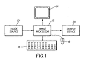
- an image processing system useful in practicing the present invention includes a color digital image source 10, such as a film scanner, digital camera, or digital image storage device such as a compact disc drive with a Picture CD.
- the digital image from the digital image source 10 is provided to an image processor 12, such as a programmed personal computer, or digital image processing workstation such as a Sun Sparc 20 workstation.
- the image processor 12 may be connected to a CRT display 14, and an operator interface such as a keyboard 16 and a mouse 18.
- the processed digital images are sent to an output device 20, such a hard copy printer, a long-term image storage device, a connection to another processor, or an image telecommunication device connected for example to the internet.
- the digital image expressed in a device independent RGB color space such as sRGB color space is first rank order filtered in a rank order filter step 22.
- the rank-order filtering is defined as where is the set of C i ( m,n ) whose value exceeds a predefined threshold T Rank while is the set of the remaining C i ( m,n ) of I .
- This operation is similar to the traditional process of trimmed median filtering. Notice that the purpose of this rank-order filtering is not to improve the visual quality of the input image as traditional image processing does; rather, it is to reduce the influence of the pixels that have very high intensity values on the subsequent statistics gathering stage 24. For instance, in situations such as over exposure, or back lit exposure, pixels with values close to 255 will be altered or excluded in the mean value calculation.
- the next step is to compute the color mean-statistics in a statistics step 24 for each color channel using I R .
- a pre-processing decision step 26 is made upon evaluating the mean statistics ⁇ m i ⁇ . If there exits m i ⁇ T M , then the pre-processing decision is 'Yes', where the threshold T M is an experimentally determined value; for example, for an 8-bit image, a value of 100 has been found to be acceptable.
- the input to the non-linear processing step is the original RGB image I .
- the non-linear processor employed in this invention is color histogram equalization, which is an image processing technique well known to those of skill in this art and thoroughly described in the literature (e.g., see “Digital Image Processing", by Gonzalez and Woods, Addison-Wesley Publishing Company, 1992).
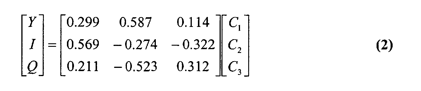
- the input image I is first converted to YIQ space to separate the luminance component and chromaticity components using the standard formula:
- the histogram equalization process is applied to Y only, resulting in an equalized luminance Y' .
- the reverse mapping from the YIQ to RGB is done by
- the original image I is sent to the gRGB conversion step 32.
- the initialization stage 21 sends an image to a skin-color detection stage 35 depending on the pre-processing decision; either the original image I or the histogram-equalized image I' is sent to the gRGB conversion step 32.
- the conversion uses the formula: where C i is the individual color channel (R, G, or B) of the input image. This conversion operation is not valid when , and the output will be set to zero.
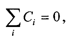
- the resultant three new elements are linearly dependent, that is so that only two elements are needed to effectively form a new space (gRG plane) that is collapsed from three dimensions to two dimensions.
- c 1 and c 2 that is, the generalized R and G, are used in skin color analysis and skin color detection.
- the skin colors in the image I gRGB are detected in a skin color detection step 30 that receives multiple ellipse vectors from an ellipse classifier 31.
- the ellipse classifier 31 is trained on a large population of images beforehand, which will be discussed below with reference to Fig. 7.
- the detected skin colors may then be optionally segmented in a segmentation step 28.
- the skin-color detection step 30 is shown in more detail in Figure 3.
- the generalized RGB image I gRGB is first projected on to the gRG plane in the in a projection step 36. This projection produces a gRG image I gRG .
- the projection is affected by simply removing the component c 3 from the gRGB image.
- the gRG image I gRG with two components c 1 and c 2 is then passed to a first (I) skin color classifier 38 which receives a first ellipse vector (ellipse vector I) as shown in Figure 3.
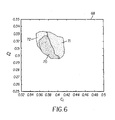
- Figure 4 illustrates an example of an ellipse 58 in gRG color space 56 that is used to designate a region in which skin color pixels are located.
- the dark region 60 in Figure 4 is the actual skin-color pixel area.
- Parameters a, b, ( o 1 , o 2 ), and ⁇ are the constants of the ellipse and define the ellipse vector produced by the ellipse classifier 31.
- Parameters a and b are the ellipse axes length, ( o 1 , o 2 ) is the center coordinates of the ellipse in the ( c 1 , c 2 ) space 56, and ⁇ is the angle between the c 1 axis and the longer axis of the ellipse.
- an intermediate skin-color mask P I ⁇ p I ( i,j ) ⁇ M ⁇ N , that is, an M ⁇ N matrix with elements p ( i,j ).
- the intermediate skin-color mask, P I is passed to an evaluation step 40.
- the evaluation procedure simply computes the ratio, ⁇ I , of the number of detected skin pixels to the image size.
- the evaluation step 40 has two branches. If ⁇ I ⁇ T ⁇ , that is, the evaluation result is 'Good', then the process branches to a skin color region masking step 42.
- the output from the first skin color classification step 38, P I is used for masking the I gRGB in the skin color region masking step 42.
- T ⁇ may take on a range of different values depending on the application, a preferred value for T ⁇ is 0.12.
- the structure and operation of the second (II) skin color classification step 44 is the same as that of the first skin color classification step 38 except it employs a different ellipse vector which determines the position, size and orientation of the ellipse in the ( c 1 , c 2 ) space.
- ellipses E1-E7 there are several possible ellipses E1-E7 that can be generated by the ellipse classifier 31.
- the idea of having multiple ellipses is to reduce false positives while providing a mechanism for detecting skin colors that deviate from a main skin color region, for example E1 in the ( c 1 , c 2 ) space 62.
- E1 in the ( c 1 , c 2 ) space 62 As an illustrative case, the use of only two such ellipses (I and II) is described with reference to Fig. 3, but it will be understood that a larger number of skin color classifiers and ellipses can be employed in the present invention.
- This first skin-color mask, P will be used in the skin color region masking step 42.
- the process branches to another classifier, the second classifier 44 for example, and both the new result and the result from the main classifier (the first classifier 38) will be evaluated and the better (or the best) one will be selected as the first skin color mask to be sent to the masking step 42.
- the evaluation process is to compute the ratio of the number of detected skin pixels to the image size. If the ratio is smaller than a predefined threshold, the classifier ellipse is then expanded, for instance, by 30% or 40% more, to include more colors.
- blond hair colored pixels 72 occur in the same region where the majority of skin colored pixels 71 reside, but next to the skin color region 70 that belong to the people having blond hairs.
- Most currently existing skin detection algorithms do not take the blond hair colored pixels into account. This can cause a problem for image understanding applications that are sensitive to the size of the area of skin color, such as redeye detection algorithms which rely on detecting the actual size of the classified skin color region.
- a technique for removal of blond hair colored pixels is described in the aforementioned copending Serial No. [our Docket No. 81321DMW], entitled “Method of Blond-Hair-Pixel Removal in Image Skin-Color Detection", which is incorporated herein by reference, and briefly summarized below.
- a typical hue conversion is performed as:
- the blond-hair-color pixel removal may take away true skin-color pixels and the resultant second skin-color mask shrinks to an unusable small region.
- the first skin-color mask P will be called back and the second the skin-color mask is discarded.
- This action is performed in an evaluation and selection step 50 following the blond-hair color detection step 52 as shown in Figure 3. If the second skin color image mask is smaller than the first skin color mask by a predetermined amount, the first skin color image mask is selected, otherwise, the second skin color image mask is selected.
- the masked RGB color image is the result of an AND operation of the selected skin color image mask and the original RGB color image I RGB . This operation is performed in a skin color region masking step 48.
- a large image pool 74 containing over a thousand images from different sources is prepared for sample skin color patch collecting. It is not necessary to collect skin patches from all prepared images.
- a set of randomly selected images should be representative enough for the whole image pool, in theory and in practice as well.
- a set of uniformly distributed indices is used to retrieve the images from the image pool and form a set of random selected images 76.
- Sample skin color patches 78 are collected manually from the retrieved images. The collected skin color patches are then converted from the RGB space to the gRGB space 80 using Equation (5) above.
- the gRG data of the gRGB image is then evaluated in term of its distribution density 82 in the gRG plane 84, that is, the ( c 1 , c 2 ) space as described above.
- the distribution density is approximated with the histogram of the gRG data.
- the distribution density is further projected onto the ( c 1 , c 2 ) space after eliminating some of its elements whose height is less than 5% of the distribution density peak.
- the projected cluster 88 forms approximately an ellipse region in the gRG plane 86.
- the final step of the ellipse classifier training is to find the parameters for the ellipse region.
- the best-fit ellipse 92 in the gRG plane 90 is computed on the basis of moments.
- An ellipse is defined by its center ( o 1 , o 2 ), its orientation ⁇ and its minor axis a and major axis b (see Figure 4).
- the orientation ⁇ can be computed by determined the least moment of inertia: where the central moments are calculated as: and finally the length of minor and major axis can be computed as:
- the above computation provides an initial set of ellipse vector [ a , b , o 1 , o 2 , ⁇ ] 94. In practice, manual adjustment is needed to best fit the final ellipse to the gRG data cluster 88.
- the subject matter of the present invention relates to digital image understanding technology, which is understood to mean technology that digitally processes a digital image to recognize and thereby assign useful meaning to human understandable objects, attributes or conditions and then to utilize the results obtained in the further processing of the digital image.
Landscapes
- Engineering & Computer Science (AREA)
- General Physics & Mathematics (AREA)
- Physics & Mathematics (AREA)
- Theoretical Computer Science (AREA)
- Multimedia (AREA)
- Oral & Maxillofacial Surgery (AREA)
- General Health & Medical Sciences (AREA)
- Human Computer Interaction (AREA)
- Health & Medical Sciences (AREA)
- Computer Vision & Pattern Recognition (AREA)
- Image Analysis (AREA)
- Image Processing (AREA)
- Facsimile Image Signal Circuits (AREA)
- Color Image Communication Systems (AREA)
Abstract
Description









Claims (5)
- A method for detecting skin color in a digital image having pixels in an RGB color space, comprising the steps of:a) performing statistical analysis of the digital color image to determine the mean RGB color values;b) if the mean value of any one of the colors is below a predetermined threshold, applying a transformation to the digital image to move skin colors in the image toward a predetermined region of the color space; andc) employing the transformed space to locate the skin color pixels in the digital color image.
- The method as claimed in claim 1 wherein step (c) further comprises the steps of:converting the transformed digital image from the RGB space to a generalized RGB space, to produce a gRGB digital image;detecting skin color pixels within the gRGB digital image;forming a first skin color image mask based on the detected skin color pixels; andemploying the first skin color image mask to locate the skin color pixels in the digital color image.
- The method as claimed in claim 2 wherein step (c) further comprises:forming a second skin color image mask based on the detected skin color pixels;selecting either the first skin color image mask or the second skin color image mask based on predetermined criteria; andemploying the selected skin color image mask to locate the skin color pixels in the digital color image.
- The method as claimed in claim 2 wherein step (c) further comprises the steps of:generating a masked gRGB image using the first skin color image mask;converting the masked gRGB image to a hue image;removing possible blond hair color pixels from the hue image to produce a modified hue image;forming a second skin color image mask based on the skin color pixels in the modified hue image;if the second skin color image mask is smaller than the first skin color image mask by a predetermined amount, selecting the first skin color image mask, otherwise, selecting the second skin color image mask; andemploying the selected skin color image mask to locate the skin color pixels in the digital color image.
- A computer program product for performing the method as claimed in claim 1.
Applications Claiming Priority (2)
| Application Number | Priority Date | Filing Date | Title |
|---|---|---|---|
| US09/692,930 US6690822B1 (en) | 2000-10-20 | 2000-10-20 | Method for detecting skin color in a digital image |
| US692930 | 2000-10-20 |
Publications (3)
| Publication Number | Publication Date |
|---|---|
| EP1223550A2 true EP1223550A2 (en) | 2002-07-17 |
| EP1223550A3 EP1223550A3 (en) | 2004-06-30 |
| EP1223550B1 EP1223550B1 (en) | 2012-12-05 |
Family
ID=24782627
Family Applications (1)
| Application Number | Title | Priority Date | Filing Date |
|---|---|---|---|
| EP01203798A Expired - Lifetime EP1223550B1 (en) | 2000-10-20 | 2001-10-08 | Method for detecting skin color in a digital image |
Country Status (3)
| Country | Link |
|---|---|
| US (1) | US6690822B1 (en) |
| EP (1) | EP1223550B1 (en) |
| JP (1) | JP3775782B2 (en) |
Cited By (6)
| Publication number | Priority date | Publication date | Assignee | Title |
|---|---|---|---|---|
| WO2006041426A3 (en) * | 2004-09-15 | 2006-06-22 | Adobe Systems Inc | Locating a feature in a digital image |
| US7251363B2 (en) | 2003-07-29 | 2007-07-31 | Ventana Medical Systems, Inc. | Method and system for creating an image mask |
| US7444022B2 (en) | 2003-12-09 | 2008-10-28 | Mitsubishi Denki Kabushiki Kaisha | Method and apparatus for separating content types in images |
| US7623707B2 (en) | 2004-09-15 | 2009-11-24 | Adobe Systems Incorporated | Hierarchically locating a feature in a digital image |
| CN104794423A (en) * | 2014-01-21 | 2015-07-22 | 厦门美图网科技有限公司 | Color space-based skin recognition method |
| GB2541865A (en) * | 2015-07-30 | 2017-03-08 | Emerald Medical Applications Ltd | Image processing system and method |
Families Citing this family (42)
| Publication number | Priority date | Publication date | Assignee | Title |
|---|---|---|---|---|
| US7088855B1 (en) * | 2001-01-22 | 2006-08-08 | Adolfo Pinheiro Vide | Method and system for removal of red eye effects |
| EP1229734A1 (en) * | 2001-01-31 | 2002-08-07 | GRETAG IMAGING Trading AG | Automatic colour defect correction |
| JP4086580B2 (en) * | 2002-07-30 | 2008-05-14 | キヤノン株式会社 | Image processing apparatus, program, and method |
| US7039222B2 (en) * | 2003-02-28 | 2006-05-02 | Eastman Kodak Company | Method and system for enhancing portrait images that are processed in a batch mode |
| EP1517542B1 (en) * | 2003-09-01 | 2010-11-10 | Samsung Electronics Co., Ltd. | Method and apparatus for adjusting colors of an image |
| US7577291B2 (en) * | 2005-03-07 | 2009-08-18 | Oplus Technologies Ltd. | Method of color correction |
| KR100695159B1 (en) | 2005-08-04 | 2007-03-14 | 삼성전자주식회사 | Algibi map generation device and method for skin color model and skin color detection device and method using same |
| US7751622B2 (en) * | 2005-08-22 | 2010-07-06 | Carestream Health, Inc. | Method and system for detection of undesirable images |
| US8254630B2 (en) * | 2006-04-28 | 2012-08-28 | Nikon Corporation | Subject extracting method and device by eliminating a background region using binary masks |
| KR100862341B1 (en) * | 2006-11-13 | 2008-10-13 | 삼성전기주식회사 | Human skin region detection device and method |
| FR2910143B1 (en) * | 2006-12-19 | 2009-04-03 | Eastman Kodak Co | METHOD FOR AUTOMATICALLY PREDICTING WORDS IN A TEXT ASSOCIATED WITH A MULTIMEDIA MESSAGE |
| ITVA20060079A1 (en) | 2006-12-19 | 2008-06-20 | St Microelectronics Srl | PIXEL CHROMATIC CLASSIFICATION METHOD AND ADAPTIVE IMPROVEMENT METHOD OF A COLOR IMAGE |
| US8437514B2 (en) * | 2007-10-02 | 2013-05-07 | Microsoft Corporation | Cartoon face generation |
| US8218862B2 (en) * | 2008-02-01 | 2012-07-10 | Canfield Scientific, Incorporated | Automatic mask design and registration and feature detection for computer-aided skin analysis |
| US8027521B1 (en) | 2008-03-25 | 2011-09-27 | Videomining Corporation | Method and system for robust human gender recognition using facial feature localization |
| US8831379B2 (en) * | 2008-04-04 | 2014-09-09 | Microsoft Corporation | Cartoon personalization |
| JP4384240B2 (en) | 2008-05-28 | 2009-12-16 | 株式会社東芝 | Image processing apparatus, image processing method, and image processing program |
| US8406482B1 (en) * | 2008-08-28 | 2013-03-26 | Adobe Systems Incorporated | System and method for automatic skin tone detection in images |
| KR101549824B1 (en) * | 2008-12-11 | 2015-09-03 | 삼성전자주식회사 | Method and apparatus for correcting skin color, digital photographing apparatus using the same |
| US20100158357A1 (en) * | 2008-12-19 | 2010-06-24 | Qualcomm Incorporated | Image processing method and system of skin color enhancement |
| US7916905B2 (en) * | 2009-02-02 | 2011-03-29 | Kabushiki Kaisha Toshiba | System and method for image facial area detection employing skin tones |
| US8319857B2 (en) * | 2009-02-26 | 2012-11-27 | Access Business Group International Llc | Apparatus and method for correcting digital color photographs |
| CN101893481B (en) * | 2009-05-18 | 2014-04-30 | 姜宁 | Method and system for testing and determining color attribute |
| JP2011221812A (en) * | 2010-04-09 | 2011-11-04 | Sony Corp | Information processing device, method and program |
| CN103106386A (en) * | 2011-11-10 | 2013-05-15 | 华为技术有限公司 | Dynamic self-adaption skin color segmentation method and device |
| JP5757259B2 (en) * | 2012-02-28 | 2015-07-29 | ブラザー工業株式会社 | Image processing apparatus and image processing program |
| US9208749B2 (en) | 2012-11-13 | 2015-12-08 | Htc Corporation | Electronic device and method for enhancing readability of an image thereof |
| CN104123698B (en) * | 2013-04-25 | 2018-05-08 | 北京信路威科技股份有限公司 | Nighttime image enhancing method applied to intelligent integral video camera |
| US8983152B2 (en) | 2013-05-14 | 2015-03-17 | Google Inc. | Image masks for face-related selection and processing in images |
| US20150030243A1 (en) | 2013-07-24 | 2015-01-29 | Di Qu | Chart for evaluating skin color and its application to efficacy evaluation of anti-aging and skin lightening products |
| US9196056B2 (en) | 2013-08-19 | 2015-11-24 | Manufacturing Techniques, Inc. | Electro-optical system and method for analyzing images of a scene to identify the presence of a target color |
| GB2519620B (en) * | 2013-10-23 | 2015-12-30 | Imagination Tech Ltd | Skin colour probability map |
| US9256950B1 (en) | 2014-03-06 | 2016-02-09 | Google Inc. | Detecting and modifying facial features of persons in images |
| US9864901B2 (en) | 2015-09-15 | 2018-01-09 | Google Llc | Feature detection and masking in images based on color distributions |
| US9547908B1 (en) | 2015-09-28 | 2017-01-17 | Google Inc. | Feature mask determination for images |
| US10497179B2 (en) | 2018-02-23 | 2019-12-03 | Hong Kong Applied Science and Technology Research Institute Company Limited | Apparatus and method for performing real object detection and control using a virtual reality head mounted display system |
| CN110706187B (en) * | 2019-05-31 | 2022-04-22 | 成都品果科技有限公司 | Image adjusting method for uniform skin color |
| US12014828B2 (en) | 2019-06-18 | 2024-06-18 | Digital Diagnostics Inc. | Using a set of machine learning diagnostic models to determine a diagnosis based on a skin tone of a patient |
| CN111861981B (en) * | 2020-05-29 | 2023-05-30 | 北京工商大学 | A fat point detection and evaluation method in image color space based on point-line-plane |
| JP2024536882A (en) * | 2021-09-29 | 2024-10-08 | フィットスキン インコーポレイテッド | Skin color determination system and method |
| EP4553717A1 (en) * | 2023-11-09 | 2025-05-14 | Siemens Healthineers AG | Method for performing a check of a stacked system |
| CN119942148B (en) * | 2025-01-03 | 2025-08-12 | 山东安迪新型材料有限公司 | Image recognition-based method and system for detecting AS-PH chromaticity of chromatic phenol |
Family Cites Families (11)
| Publication number | Priority date | Publication date | Assignee | Title |
|---|---|---|---|---|
| JPS52156624A (en) | 1976-06-22 | 1977-12-27 | Fuji Photo Film Co Ltd | Detection of skin color of color film |
| JPH0250859A (en) * | 1988-08-11 | 1990-02-20 | Dainippon Screen Mfg Co Ltd | Method and apparatus for setting color separation condition |
| US5128711A (en) | 1989-04-28 | 1992-07-07 | Fuji Photo Film Co., Ltd. | Apparatus for recording position information of principal image and method of detecting principal image |
| US6249317B1 (en) * | 1990-08-01 | 2001-06-19 | Minolta Co., Ltd. | Automatic exposure control apparatus |
| US6072526A (en) * | 1990-10-15 | 2000-06-06 | Minolta Co., Ltd. | Image sensing device that can correct colors corresponding to skin in a video signal |
| US5488429A (en) * | 1992-01-13 | 1996-01-30 | Mitsubishi Denki Kabushiki Kaisha | Video signal processor for detecting flesh tones in am image |
| JP3370770B2 (en) * | 1994-04-15 | 2003-01-27 | 松下電器産業株式会社 | Video signal skin color reproduction circuit |
| US5715377A (en) * | 1994-07-21 | 1998-02-03 | Matsushita Electric Industrial Co. Ltd. | Gray level correction apparatus |
| JP3799633B2 (en) * | 1995-06-16 | 2006-07-19 | セイコーエプソン株式会社 | Face image processing method and face image processing apparatus |
| US6343141B1 (en) * | 1996-10-08 | 2002-01-29 | Lucent Technologies Inc. | Skin area detection for video image systems |
| KR100343223B1 (en) * | 1999-12-07 | 2002-07-10 | 윤종용 | Apparatus for eye and face detection and method thereof |
-
2000
- 2000-10-20 US US09/692,930 patent/US6690822B1/en not_active Expired - Fee Related
-
2001
- 2001-10-08 EP EP01203798A patent/EP1223550B1/en not_active Expired - Lifetime
- 2001-10-19 JP JP2001322732A patent/JP3775782B2/en not_active Expired - Fee Related
Cited By (9)
| Publication number | Priority date | Publication date | Assignee | Title |
|---|---|---|---|---|
| US7251363B2 (en) | 2003-07-29 | 2007-07-31 | Ventana Medical Systems, Inc. | Method and system for creating an image mask |
| US7444022B2 (en) | 2003-12-09 | 2008-10-28 | Mitsubishi Denki Kabushiki Kaisha | Method and apparatus for separating content types in images |
| WO2006041426A3 (en) * | 2004-09-15 | 2006-06-22 | Adobe Systems Inc | Locating a feature in a digital image |
| US7623707B2 (en) | 2004-09-15 | 2009-11-24 | Adobe Systems Incorporated | Hierarchically locating a feature in a digital image |
| US8081818B2 (en) | 2004-09-15 | 2011-12-20 | Adobe Systems Incorporated | Locating a feature in a digital image |
| US8724903B2 (en) | 2004-09-15 | 2014-05-13 | Adobe Systems Incorporated | Locating a feature in a digital image |
| CN104794423A (en) * | 2014-01-21 | 2015-07-22 | 厦门美图网科技有限公司 | Color space-based skin recognition method |
| CN104794423B (en) * | 2014-01-21 | 2019-02-12 | 厦门美图网科技有限公司 | A kind of skin identification method based on color space |
| GB2541865A (en) * | 2015-07-30 | 2017-03-08 | Emerald Medical Applications Ltd | Image processing system and method |
Also Published As
| Publication number | Publication date |
|---|---|
| EP1223550B1 (en) | 2012-12-05 |
| EP1223550A3 (en) | 2004-06-30 |
| JP3775782B2 (en) | 2006-05-17 |
| US6690822B1 (en) | 2004-02-10 |
| JP2002197457A (en) | 2002-07-12 |
Similar Documents
| Publication | Publication Date | Title |
|---|---|---|
| EP1223550B1 (en) | Method for detecting skin color in a digital image | |
| US7343028B2 (en) | Method and apparatus for red-eye detection | |
| US7110575B2 (en) | Method for locating faces in digital color images | |
| EP1700269B1 (en) | Detection of sky in digital color images | |
| US7583294B2 (en) | Face detecting camera and method | |
| US7171044B2 (en) | Red-eye detection based on red region detection with eye confirmation | |
| EP1231565A1 (en) | Image colour correction based on image pattern recognition, the image pattern including a reference colour | |
| US7120279B2 (en) | Method for face orientation determination in digital color images | |
| US6711286B1 (en) | Method for blond-hair-pixel removal in image skin-color detection | |
| JP3373008B2 (en) | Image area separation device | |
| EP1324265B1 (en) | Method and system for sharpening an image based on image content | |
| US7403654B2 (en) | Enhanced automatic red eye removal | |
| US8446494B2 (en) | Automatic redeye detection based on redeye and facial metric values | |
| US8379117B2 (en) | Detecting red eye filter and apparatus using meta-data | |
| JP2002109525A (en) | Image processing path changing method based on saliency and appeal of image | |
| JP2002269558A (en) | A method of calculating noise from digital images using color cross-correlation statistics. | |
| WO2008119368A1 (en) | Method for red eye detection in a digital image |
Legal Events
| Date | Code | Title | Description |
|---|---|---|---|
| PUAI | Public reference made under article 153(3) epc to a published international application that has entered the european phase |
Free format text: ORIGINAL CODE: 0009012 |
|
| AK | Designated contracting states |
Kind code of ref document: A2 Designated state(s): AT BE CH CY DE DK ES FI FR GB GR IE IT LI LU MC NL PT SE TR |
|
| AX | Request for extension of the european patent |
Free format text: AL;LT;LV;MK;RO;SI |
|
| PUAL | Search report despatched |
Free format text: ORIGINAL CODE: 0009013 |
|
| AK | Designated contracting states |
Kind code of ref document: A3 Designated state(s): AT BE CH CY DE DK ES FI FR GB GR IE IT LI LU MC NL PT SE TR |
|
| AX | Request for extension of the european patent |
Extension state: AL LT LV MK RO SI |
|
| RIC1 | Information provided on ipc code assigned before grant |
Ipc: 7G 06T 5/00 A Ipc: 7G 06T 7/40 B Ipc: 7G 06T 5/40 B Ipc: 7H 04N 1/62 B Ipc: 7H 04N 1/60 B |
|
| 17P | Request for examination filed |
Effective date: 20041203 |
|
| AKX | Designation fees paid |
Designated state(s): DE FR GB |
|
| 17Q | First examination report despatched |
Effective date: 20050223 |
|
| GRAP | Despatch of communication of intention to grant a patent |
Free format text: ORIGINAL CODE: EPIDOSNIGR1 |
|
| GRAS | Grant fee paid |
Free format text: ORIGINAL CODE: EPIDOSNIGR3 |
|
| GRAA | (expected) grant |
Free format text: ORIGINAL CODE: 0009210 |
|
| AK | Designated contracting states |
Kind code of ref document: B1 Designated state(s): DE FR GB |
|
| REG | Reference to a national code |
Ref country code: GB Ref legal event code: FG4D |
|
| REG | Reference to a national code |
Ref country code: DE Ref legal event code: R096 Ref document number: 60147451 Country of ref document: DE Effective date: 20130131 |
|
| REG | Reference to a national code |
Ref country code: DE Ref legal event code: R082 Ref document number: 60147451 Country of ref document: DE Representative=s name: MUELLER-BORE & PARTNER PATENTANWAELTE, EUROPEA, DE |
|
| REG | Reference to a national code |
Ref country code: DE Ref legal event code: R082 Ref document number: 60147451 Country of ref document: DE Representative=s name: MUELLER-BORE & PARTNER PATENTANWAELTE, EUROPEA, DE Effective date: 20130430 Ref country code: DE Ref legal event code: R081 Ref document number: 60147451 Country of ref document: DE Owner name: INTELLECTUAL VENTURES FUND 83 LLC (N.D.GES.D.S, US Free format text: FORMER OWNER: EASTMAN KODAK CO., ROCHESTER, US Effective date: 20121205 Ref country code: DE Ref legal event code: R081 Ref document number: 60147451 Country of ref document: DE Owner name: INTELLECTUAL VENTURES FUND 83 LLC (N.D.GES.D.S, US Free format text: FORMER OWNER: EASTMAN KODAK COMPANY, ROCHESTER, US Effective date: 20130430 Ref country code: DE Ref legal event code: R082 Ref document number: 60147451 Country of ref document: DE Representative=s name: MUELLER-BORE & PARTNER PATENTANWAELTE PARTG MB, DE Effective date: 20130430 Ref country code: DE Ref legal event code: R081 Ref document number: 60147451 Country of ref document: DE Owner name: INTELLECTUAL VENTURES FUND 83 LLC (N.D.GES.D.S, US Free format text: FORMER OWNER: EASTMAN KODAK CO., ROCHESTER, N.Y., US Effective date: 20121205 Ref country code: DE Ref legal event code: R081 Ref document number: 60147451 Country of ref document: DE Owner name: INTELLECTUAL VENTURES FUND 83 LLC (N.D.GES.D.S, US Free format text: FORMER OWNER: EASTMAN KODAK COMPANY, ROCHESTER, N.Y., US Effective date: 20130430 |
|
| REG | Reference to a national code |
Ref country code: GB Ref legal event code: 732E Free format text: REGISTERED BETWEEN 20130711 AND 20130717 |
|
| PLBE | No opposition filed within time limit |
Free format text: ORIGINAL CODE: 0009261 |
|
| STAA | Information on the status of an ep patent application or granted ep patent |
Free format text: STATUS: NO OPPOSITION FILED WITHIN TIME LIMIT |
|
| REG | Reference to a national code |
Ref country code: FR Ref legal event code: TP Owner name: INTELLECTUAL VENTURES FUND 83 LLC, US Effective date: 20130919 |
|
| 26N | No opposition filed |
Effective date: 20130906 |
|
| REG | Reference to a national code |
Ref country code: DE Ref legal event code: R097 Ref document number: 60147451 Country of ref document: DE Effective date: 20130906 |
|
| PGFP | Annual fee paid to national office [announced via postgrant information from national office to epo] |
Ref country code: GB Payment date: 20140925 Year of fee payment: 14 |
|
| PGFP | Annual fee paid to national office [announced via postgrant information from national office to epo] |
Ref country code: FR Payment date: 20140924 Year of fee payment: 14 Ref country code: DE Payment date: 20141028 Year of fee payment: 14 |
|
| REG | Reference to a national code |
Ref country code: DE Ref legal event code: R119 Ref document number: 60147451 Country of ref document: DE |
|
| GBPC | Gb: european patent ceased through non-payment of renewal fee |
Effective date: 20151008 |
|
| PG25 | Lapsed in a contracting state [announced via postgrant information from national office to epo] |
Ref country code: GB Free format text: LAPSE BECAUSE OF NON-PAYMENT OF DUE FEES Effective date: 20151008 Ref country code: DE Free format text: LAPSE BECAUSE OF NON-PAYMENT OF DUE FEES Effective date: 20160503 |
|
| REG | Reference to a national code |
Ref country code: FR Ref legal event code: ST Effective date: 20160630 |
|
| PG25 | Lapsed in a contracting state [announced via postgrant information from national office to epo] |
Ref country code: FR Free format text: LAPSE BECAUSE OF NON-PAYMENT OF DUE FEES Effective date: 20151102 |