EP1223104A1 - Procédé de guidage d'un système d'actionneurs gyroscopiques - Google Patents
Procédé de guidage d'un système d'actionneurs gyroscopiques Download PDFInfo
- Publication number
- EP1223104A1 EP1223104A1 EP01403326A EP01403326A EP1223104A1 EP 1223104 A1 EP1223104 A1 EP 1223104A1 EP 01403326 A EP01403326 A EP 01403326A EP 01403326 A EP01403326 A EP 01403326A EP 1223104 A1 EP1223104 A1 EP 1223104A1
- Authority
- EP
- European Patent Office
- Prior art keywords
- configuration
- profile
- gyroscopic
- actuators
- angular momentum
- Prior art date
- Legal status (The legal status is an assumption and is not a legal conclusion. Google has not performed a legal analysis and makes no representation as to the accuracy of the status listed.)
- Granted
Links
- 238000000034 method Methods 0.000 title claims description 28
- 230000008569 process Effects 0.000 title description 11
- 230000007704 transition Effects 0.000 claims abstract description 4
- 230000001133 acceleration Effects 0.000 claims description 23
- 230000003247 decreasing effect Effects 0.000 claims description 4
- 238000002347 injection Methods 0.000 abstract 1
- 239000007924 injection Substances 0.000 abstract 1
- 241000287107 Passer Species 0.000 description 9
- 230000008859 change Effects 0.000 description 7
- 230000006870 function Effects 0.000 description 7
- 238000004364 calculation method Methods 0.000 description 6
- 230000008901 benefit Effects 0.000 description 4
- 230000007423 decrease Effects 0.000 description 3
- 239000011159 matrix material Substances 0.000 description 3
- 238000005259 measurement Methods 0.000 description 2
- 230000003071 parasitic effect Effects 0.000 description 2
- 239000007787 solid Substances 0.000 description 2
- 230000001052 transient effect Effects 0.000 description 2
- 230000033228 biological regulation Effects 0.000 description 1
- 230000005284 excitation Effects 0.000 description 1
- 230000003287 optical effect Effects 0.000 description 1
- 230000004044 response Effects 0.000 description 1
Images


Classifications
-
- B—PERFORMING OPERATIONS; TRANSPORTING
- B64—AIRCRAFT; AVIATION; COSMONAUTICS
- B64G—COSMONAUTICS; VEHICLES OR EQUIPMENT THEREFOR
- B64G1/00—Cosmonautic vehicles
- B64G1/22—Parts of, or equipment specially adapted for fitting in or to, cosmonautic vehicles
- B64G1/24—Guiding or controlling apparatus, e.g. for attitude control
- B64G1/28—Guiding or controlling apparatus, e.g. for attitude control using inertia or gyro effect
- B64G1/286—Guiding or controlling apparatus, e.g. for attitude control using inertia or gyro effect using control momentum gyroscopes (CMGs)
Definitions
- the invention relates to gyroscopic actuator systems used in satellites, and more specifically, a law for guiding an actuator system gyro.
- Gyroscopic actuator systems are used in satellites, which consist of several kinetic wheels driven in rotation.
- the axes of wheels are mounted on universal joints.
- Each actuator keeps its moment constant kinetics in amplitude and generates torque by changing the direction of sound angular momentum in the satellite frame, using the gimbal.
- the movements of system gimbals cause a variation in the total angular momentum of the system; such variations allow the attitude of the satellite to be controlled. So we talk in the sequence either of variation in attitude or variation in angular momentum; the latter term, however, would be the most appropriate term when considering as the actuator system independently of a satellite.
- the angular momentum of an actuator is called, so known per se, a vector whose direction is that of the axis of rotation of the actuator, and whose intensity is equal to the product of the moment of inertia of the actuator by the speed of rotation.
- the meaning of the angular momentum is given by a convention related to the orientation of the coordinate system in space.
- the kinetic moment of a actuator system is equal to the vector sum of the angular moments of different actuators.
- FR-A-2 786 283 describes a method for controlling the attitude of a satellite, by speed control of the gyrodynes gimbals of a cluster of girodynes.
- This document proposes to determine from initial and final conditions in term attitude / angular velocity / time a cluster configuration distant from any singular configuration, and such that the exchange of angular momentum causes the desired maneuver.
- This document then proposes to bring simultaneously and independent the orientation of each universal joint in its set orientation, thanks to an angular position setpoint, sent in open loop in the local servo in angular position of the universal joints.
- the open loop setpoint is almost instantaneous with respect to the response time the closed-loop control of the attitude control system.
- This solution nevertheless induces disturbances in the attitude guidance of the satellite; in fact, the accuracy of the angular position of the gimbals can be worth a few microradians; an open loop, even of short duration, affects the accuracy of the guide.
- this solution involves a significant amount of quiet time; the disturbances caused by the application of the angle setpoint in open loop are still sensitive to the end of the change in attitude.
- this solution implies, for a given guidance strategy, gyroscopic actuators capable of withstand a high gimbal speed - in other words having a torque of high output.
- a finite number of reference configurations allowing all of the possible maneuvers.
- this number is finite, we can store a number also finished continuous and precalculated trajectories, which allow to pass from one reference configuration to another.
- For a maneuver it suffices to identify a reference configuration allowing the maneuver, then if necessary to switch from a current configuration to the reference configuration identified, using a trajectory calculated in advance. It is thus possible before a maneuver to go from a configuration that can cause a singularity during the maneuver to another configuration in the vicinity of which the maneuver can be performed without risk of singularity.
- the gyroscopic actuator system is controlled by a closed loop control system, and the passage step is carried out by injecting a profile in the control system.
- Profile can be defined by gimbal speeds of actuators gyroscopic, by couples of the motors of the cardan shafts of the actuators gyroscopic or by the intensity of the currents applied to the motors of gimbals of gyroscopic actuators.
- the profile has a gimbal speed of the actuators null at the start and at the end of the profile.
- a profile presents an acceleration of the gimbals of the actuators zero at the beginning as at the end in profile. It is also advantageous if the profile has a cardan speed of the actuators increasing then decreasing, the speed reaching the maximum speed accepted in the gyroscopic actuator system. In this case, it is advantageous that the maximum acceleration allowed in the gyroscopic actuator system is reached when the speed is increasing and when the speed is decreasing.
- the passage step can be carried out at the same time as the start of the generation of angular momentum; it can also last less than 20%, preferably less than 10% of the current generation time kinetic.
- the satellite has a closed loop control system for the gyroscopic actuator system and an open loop input applying one of the profiles to the gyroscopic actuator system.
- the profile stored in the satellite can be defined by gimbal speeds gyroscopic actuators, by torques of the motors of the universal joints gyroscopic actuators or by the intensity of the currents applied to gimbal motors of gyroscopic actuators.
- the invention is described with reference to a gyroscopic actuator system having a moment zero kinetics at rest; this is only an example of a classic configuration of a gyroscopic actuator system.
- the invention can also be applied to a system gyroscopic actuators always having a non-zero angular momentum.
- a number of configurations C i are then determined, called in the following reference configurations, which are such that the set of free directions covers all the possible directions.
- the set of free directions covers all the possible directions.
- any maneuver - i.e. any choice of a angular momentum value to generate - is possible from of a reference configuration.
- the problem is to switch to another configuration of reference, which allows the maneuver.
- the invention is based on the observation that it is enough to allow any maneuver without risking singularities, to define a finite number of configurations reference. Since the number of reference configurations is finite, there is no that a finite number of possible passages from a reference configuration to a other. Therefore, it suffices to define in advance a finite number of profiles allowing switch from one reference configuration to another.
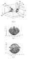
- FIG. 1 shows a schematic representation of the gyroscopic actuator system. Is brought to the represents a direct orthonormal reference (x, y, z); the benchmark is said to be direct in that it defines for the kinetic moment a convention of meaning: a rotation of axis z which brings the x axis on the y axis is represented by a vector which is positive on the z axis. On the face appears in dotted lines the structure 2 of the satellite.
- the actuators are arranged on the faces of a pyramid; for ease of explanation, we considered a pyramid with a pyramidal angle of 45 °; in other words, each side of the pyramid forms with the vertical an angle of 45 °.
- the first actuator gyroscopic 4 has a gimbal 6 movable in rotation about an axis 8 having a director vector (1,0, 1). In the position shown in the figure, the wheel 10 carried by this gimbal 6 is rotated in the plane (x, z) in the direction that takes the unit vector (1, 0, 0) to the unit vector (0, 0, 1). The kinetic moment therefore has a positive value along the y axis, which is represented in the figure by the vector 12.
- the angular momentum vector has coordinates (0, h, 0), with h the product of the moment of inertia of the wheel 10 by the speed of rotation of this wheel.
- the other actuators 14, 16 and 18 of the gyroscopic actuator system have axes of rotation of the universal joints whose respective directions are (0, 1, 1), (-1, 0, 1) and (0, -1, 1).
- the angular moments of the wheels of the four actuators 4, 14, 16 and 18 are worth respectively (0, h, 0), (-h, 0, 0), (0, -h, 0) and (h, 0, 0); here we assume that the four actuators are identical.
- the configuration of the figure is a configuration of zero total angular momentum.
- direction y is not a free direction for the configuration of the gyroscopic actuator system shown in Figure 1.
- the configuration of the gyroscopic actuator system shown in Figure 1 is therefore suitable when one wishes to generate a directed angular momentum along the z axis, or in the vicinity of this axis; however, it is not suitable as starting configuration if one wishes to generate a directed kinetic moment in the plane (x, y).
- We can therefore consider that the directions included in a solid angle containing the z axis are free directions for the configuration of the figure 1.
- a solid angle inside a double cone of revolution of axis z and 45 ° apex angle is suitable.
- a configuration is obtained for the angles ( ⁇ , - ⁇ , ⁇ , - ⁇ ) of the gimbals of the actuators 4, 14, 16 and 18, with ⁇ a non-zero angle less than 90 °.
- the angular moments of the actuators 4 and 16 are directed upwards; the sum of their angular moments is directed upwards along the z axis.
- the moments kinetics of actuators 14 and 18 are directed downwards and the sum of their angular momentum is directed downward along the z axis.
- the total angular moment is zero.
- the direction z is not a free direction.
- the direction (1, 1, 0) is a free direction: it is possible to vary the directions of the actuators, so that the moment total kinetics remains zero along the perpendicular directions (1, -1, 0) and z, and increases in absolute value monotonically along the direction (1, 1, 0), for reach a maximum positive or negative value on this direction.
- This is simply obtained using a law allowing to place an order in attitude to control of the four actuators; this boils down to the inversion of a rectangular matrix.
- This inversion is possible when the determinant is not null - that is to say in the absence of singularity.
- One possible solution is to use the Moore-Penrose pseudo-inverse. This solution is well known to those skilled in the art. specialist trade in gyroscopic actuators. It has the advantage of minimize the energy to reach a given angular moment.
- the direction (1, -1, 0) is a free direction: it is possible to vary the directions of the actuators, so that the moment total kinetics remains zero along the perpendicular directions (1, 1, 0) and z, and increases in absolute value monotonically along the direction (1, -1, 0).
- the choice of the angle ⁇ depends on the structure of the gyroscopic actuator system. For a system with actuators on the walls of a pyramid, a value between 30 ° and 60 ° is appropriate; for a pyramidal angle of 30 °, the value of ⁇ can be chosen at 40 °.
- the choice of a given angle ⁇ depends on the structure of the actuator system, and in particular on the pyramidal angle. In practice, for a pyramidal configuration, a choice of ⁇ slightly greater than the value of the pyramidal angle turns out to be suitable; for example 10 ° more than the pyramidal angle.
- a value of ⁇ too low leads to configurations C + or C - with free directions too close to those of the configuration C 0 ; too large a value of ⁇ approximates a configuration (90 °, -90 °, 90 °, -90 °) which is an internal singularity.
- FIG. 4 shows the free directions for each of these configurations; for the representations of the figures, a system of pyramidal gyroscopic actuators is considered, with a pyramidal angle of 36 ° and an angle ⁇ of 45 °.
- the figures are graduated in Nms, with a kinetic moment H of 19 Nms per actuator.
- Figures 2 to 4 show the angular momentum envelopes for the reference configurations C - , C 0 and C + .
- FIG. 3 shows for example that it is possible in the configuration C 0 to reach maximum angular moments in the direction z, but that the angular moments reached in the plane (x, y) are rather weak.
- Figure 4 shows that one quickly reaches a singularity from the C + configuration, if one seeks to obtain a angular momentum directed towards the positive z axis.
- FIGS. 6 and 9 confirm the discussion of the free directions of the configuration C 0 , mentioned above.
- Figures 8 and 10 confirm that the free directions of configurations C - and C + are indeed the bisectors (1, -1, 0) and (1, 1,0) of the plane (x, y).
- one of the reference configurations C + or C - is used .
- the choice of one or the other of these configurations depends on the azimuth; if the azimuth of the tangent is positive, we can choose the configuration C + and otherwise the direction C - .
- the foregoing discussion relates essentially to maximum values of the angular momentum in a given direction; if the value of the angular momentum to be obtained is low, it may be possible to obtain it from any initial configuration. In this case, any reference configuration is suitable for the operation.
- the configuration C 0 makes it possible to reach kinetic moments in the plane (x, y) without singularity, if they are less than 20 Nms as standard.
- the example in Figure 1 shows, for a given structure of a system of gyroscopic actuators, that it is possible to define configurations of reference; for any direction of angular momentum, there is a configuration of reference from which we can reach a maximum value of the moment kinetics in this given direction, without going through an internal singularity.
- the example in Figure 1 provides the possible configurations for a system pyramidal gyroscopic actuators; it would also be possible to add other configurations to the proposed reference configurations.
- the reference configurations can be determined experimentally for a given gyroscopic actuator system, which would have a different structure.
- a system of actuators gyroscopic it is possible for a system of actuators gyroscopic to define a set of reference configurations, in number finished. Any maneuver - that is to say any generation of a kinetic moment - can be performed from a reference configuration. If the actuator system gyroscopic is not in a configuration close to the configuration of chosen reference, it suffices to switch from the current reference configuration to the configuration chosen; this passage can be carried out as explained with reference to FIG. 15, by injecting a predetermined path into the open loop in the actuator gimbal control system.
- the gyro actuator system is in normal operation in a configuration which is close to a reference configuration; in fact, if we start from a reference configuration, it is possible to revert to such a configuration of reference after generating the angular momentum necessary for the maneuver. This is ensured by the law of guidance chosen; the Moore-Penrose pseudo-inverse ensures a return to the initial configuration: in fact, it minimizes the energy required to go from a zero angular momentum to a given angular momentum; the path reverse therefore takes place at minimum energy, and brings the actuator system back into the same configuration.
- the actuator system at the end of the maneuver is always found in the vicinity of a reference configuration, if it was before the maneuver in the vicinity of this configuration. This means that it is easy to recognize the reference configuration in the vicinity of which the actuator system is at a given time.
- profile 1 makes it possible to pass from the configuration C 0 to the configuration C + ;
- profile 2 allows you to go from configuration C - to configuration C + ;
- profile 3 allows you to go from configuration C - to configuration C 0 .
- each profile has a zero speed at the start and end of the profile; it is also advantageous for each profile to have zero acceleration at the start and end of profile.
- a profile used to go through a gyroscopic actuator from an angle of 0 ° to 40 ° The profile is generated in (1-cos) from the third derivative of the angular position of the gimbal of the actuator.
- the profile parameters are the rise time at maximum torque, maximum acceleration, maximum speed and angular travel desired - 40 ° in the example.
- the profile proposed in the example is also a profile short as possible, in which the maximum permissible values of angular velocity and angular acceleration are reached.
- Such a profile has the advantage of duration as short as possible while respecting the operating constraints of the system; it is then possible without disturbances to apply the profile at the start of each maneuver, superimposed on the maneuver.
- a profile duration of the order of 1 s is typically low compared to the duration of the maneuver, which can be of the order of 5 to 20s. In this case, the duration of the maneuver is less than 20% or even 10% of the duration of the maneuver.
- a angular momentum value low can be obtained from any configuration, without risk of singularity; the corresponding short maneuvers, of a typical duration of 1 or 2 s do not require no change from the reference configuration to another configuration.
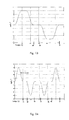
- Figure 14 is a graph of the third derivative of the angle of a gyroscopic actuator. Time is plotted on the x-axis, and the third derivative on the y-axis, in radians / 3 .
- the graph in Figure 14 presents three parts.
- the first part - in the figure between 0 and t 3 - corresponds to the increase in speed to reach the maximum angular speed, which appears in Figure 12; during this first part, the third derivative is successively positive from 0 to t 1 , constant from t 1 to t 2 , then negative from t 2 to t 3 ; as shown in Figure 13, this first part corresponds to an acceleration to a maximum acceleration, then to a deceleration to reach zero acceleration when the speed reaches a maximum speed.
- This first part typically has a duration t 3 of the order of 0.2 to 1 s.
- the first part consists of the concatenation of a function in A (1-cos (t)) between 0 and t 1 , with A real and t time, of a constant and zero function between t 1 and t 2 , and of a function -A (1-cos (tt 2 ) between t 2 and t 3 ; the value of the constant A depends on the maximum acceleration admitted by the system, which is reached at l 'instant t 1.
- the duration t 2 - t 1 depends on the maximum speed allowed, and is adjusted so that the maximum speed is reached at time t 3 .
- the second part of the graph - in the figure between t 3 and t 4 - corresponds to the range of rotation at maximum speed.
- the duration of this range of rotation at maximum speed depends on the angular clearance to be obtained; in other words, once the first and third parts have been determined, the duration of the third part can be adapted according to the angle to be obtained.
- the third part of the graph - between the instants t 4 and t 7 is essentially symmetrical with the first part; it corresponds to deceleration from maximum speed to zero speed; as in the first part, one decelerates to reach the maximum negative allowed value of the acceleration, then one reduces (in absolute value) the acceleration to reach a zero acceleration at the end of the third period.
- Figure 13 shows a graph of angular acceleration, with time on the abscissa and acceleration in radians / s 2 on the ordinate.
- the first part in which the acceleration increases until reaching a maximum value - 4 radians / s 2 in the example - then decreases to a zero value.
- the acceleration is zero.
- the acceleration decreases until reaching a maximum negative value, remains constant then increases until a zero value.
- Figure 12 shows a graph of angular velocity, with time on the abscissa and velocity in radians / s on the ordinate. During the first part, the speed increases to reach the maximum speed; the gimbal moves at the maximum speed between t 3 and t 4 , then the speed decreases between t 4 and t 7 to zero speed.
- Figure 11 shows a graph of the angle versus time. The angle increases monotonously from 0 ° to 40 °. Note on the graphs of Figures 12 and 13 that the speed and the acceleration are zero both at the start of the profile and at the end of the profile.
- Figures 1 to 14 show only one example of a profile. It is notably possible to obtain a profile presenting at the beginning as at the end speeds and zero accelerations with a function other than the 1-cos (t) function proposed in the Figure 14; we could for example use a polynomial function to generate the curve of figure 14, then integrate it to obtain the curves of figures 11, 12 and 13.
- Figures 11 to 14 only show a curve for moving a actuator with an angle of around 40 °. It is possible to use a similar curve to move the actuator at an angle of -40 °, taking simply the opposite of the proposed curve.
- the figures offer an example a profile allowing to pass from a configuration to another configuration.
- the parameters proposed with reference to these figures make it possible to vary the profile to adapt it to the desired angular variation, at the speed maximum actuator, maximum acceleration or profile duration.
- the curve can be stored as a table of speed values for different times; we can also store the curve in an analytical form. This can be particularly interesting when the parameters of the curve - and including angular travel - may vary. Defining in advance profiles and their storage allows to embed all the parameters of navigation, while avoiding singularities. Compared to the guidance solution continuous global, the process described above does not involve heavy calculation: it suffices to determine the closest reference configuration, choose the configuration of reference according to the maneuver to come, and to apply a predefined profile. he it is therefore also not necessary to download the results of a calculation, and the elements necessary for guidance can be loaded. Unlike the solution of local guidance of the state of the art, the proposed method makes it possible to avoid effectively the singularities, and has a real predictive aspect.
- the method described above does not involve sudden changes in speed and actuator angles.
- the process is simpler to implement, since it does not imply a calculation of the final configuration or the initial configuration; he just identify for example in a table the reference configuration adapted to maneuver, determine the current reference configuration, and read in a profile table allowing to pass from one to the other.
- the method proposes to continuously follow a satellite profile, without generating any parasitic kinetic moments. At any time in the profile allowing to pass from one reference configuration to another reference configuration, the moment total kinetics of the system is zero. This is not the case in the solution proposed in FR-A-2 786 283: variations of angles are applied to the actuators which generate necessarily parasitic angular moments; these cannot be overlooked - according to this document - only because of their short duration. This explains why the process described here does not involve tranquilization like the solution proposed in FR-A-2 786,283.
- FR-A-2 786 283 involves high cardanic speeds; the actuator system is not only dimensioned by the torques to be produced, but also by the need to allow high cardan speeds during the reconfiguration of the gimbals. These high speeds are equivalent to a capacity to produce a significant torque.
- the system is oversized to allow re setup.
- the process described here does not assume high speeds; it is interesting to limit the duration of the reconfiguration, but it is not essential.
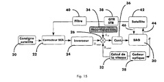
- FIG. 6 An example of a control loop is described with reference to FIG. 6 for a gyroscopic actuator system of the type of that of FIG. 1.
- Is applied to the loop 20 input a satellite setpoint - for example a quaternion and speed guidance.
- This instruction is applied to a corrector of the attitude control system 22.
- This corrector also receives a signal measure described below. From the setpoint and the measurement signal, the corrector calculates an error signal; this error signal is always in quaternion and quickly; it is applied to an inverter 24.
- the inverter 24 calculates from the signal error command angles to apply to different actuators. We can use for the inverter 24 an algorithm based on the Moore-Penrose pseudo-inverse.
- the inverter outputs speed signals target angle for the different actuators. These signals are applied to a summation input of a subtractor 26. This also receives on an input subtracting an estimated angular speed of the different actuators. Speed angle can be estimated using an optical encoder 28 measuring the angles of the system 30 actuators; the measured angle values are then applied to a speed computer 32 and output at the subtraction input of the subtractor 26.
- the subtracter also receives on another summing input the signals of profile 34; these signals are therefore injected into the system regulation loop of gyroscopic actuators.
- the signals of the profile are injected, at the start of maneuver or before the start of the maneuver, when it is detected that the current configuration of the gyroscopic actuator system does not allow the maneuver without risk of singularity - in other words, the angular moment at generate is not in a free direction for the most basic reference configuration close to the current configuration.
- the sum of the reconfiguration profile signals and the difference between the guidance law signals and the estimated angular velocity signals is applied to the actuators of the system 30, through a gimbal controller 36.
- the estimate of the real state of the satellite, applied to the corrector 22, comes from the combined measurements of a gyrostellar system 38; this one serves as satellite attitude sensor. Its output signal is applied to the corrector through a filter 40.
- FIG. 15 again schematically shows the satellite 42; arrow 44 indicates the torque applied to the satellite by the actuator system; arrow 46 indicates the torque applied to the gimbals of the gyroscopic actuator system by changes in attitude of the satellite.
- the command in Figure 15 is just an example of an command possible; we will simply note that it is proposed to inject in open loop, in this command of the gyroscopic actuator system, the profile of re setup. This profile is applied without the need to deactivate the satellite attitude control, as proposed in document FR-A-2 786,283.
- a satellite implementing the method described here therefore comprises a gyroscopic actuator system, which presents a set of configurations of reference, as explained above.
- the satellite has a memory or another means of storage; the memory contains the angle variation profiles actuators for switching from one reference configuration to another.
- the satellite also advantageously has a control loop of the type of that of FIG. 15, with an entry for applying a profile.
- the present invention is not limited to the examples and modes described and represented, but it is likely to be numerous variants accessible to those skilled in the art.
- we considered a four actuator system it is of course possible to change the number actuators, as well as their configuration.
- the feedback loop for control actuators shown in Figure 15 can be changed; finally, although the configuration change profile can be overlaid at the start of the maneuver, it is also possible to change the reconfiguration with the start of the maneuver.
Landscapes
- Engineering & Computer Science (AREA)
- Remote Sensing (AREA)
- Chemical & Material Sciences (AREA)
- Combustion & Propulsion (AREA)
- Radar, Positioning & Navigation (AREA)
- Aviation & Aerospace Engineering (AREA)
- Control Of Position, Course, Altitude, Or Attitude Of Moving Bodies (AREA)
- Gyroscopes (AREA)
- Constituent Portions Of Griding Lathes, Driving, Sensing And Control (AREA)
Abstract
Description
- la définition de configurations de référence, un moment cinétique pouvant être généré sans passer par une singularité à partir d'au moins une configuration de référence;
- la définition de profils permettant de passer d'une configuration de référence à une autre;
- pour générer un moment cinétique, le choix d'une configuration de référence à partir de laquelle le moment cinétique peut être généré sans passer par une singularité; et
- si la configuration courante du système d'actionneurs gyroscopiques n'est pas proche de la configuration de référence, le passage de la configuration actuelle à la configuration de référence à l'aide d'un profil.
- un système d'actionneurs gyroscopiques, ayant un ensemble de configurations de référence, un moment cinétique pouvant être généré sans passer par une singularité à partir d'au moins une configuration de référence;
- des profils permettant de passer d'une configuration de référence à une autre, les profils étant stockés dans le satellite.
- figure 1, une représentation schématique d'un système d'actionneurs gyroscopiques;
- figures 2 à 4, des enveloppes de moment cinétique pour des configurations de référence du système de la figure 1;
- figures 5 à 10, des coupes dans différents plans des enveloppes des figures 2 à 4;
- figure 11, un graphe du profil de guidage en position d'un actionneur gyroscopique;
- figure 12, un graphe de vitesse du profil de la figure 11 ;
- figure 13, un graphe de l'accélération du profil de la figure 11 ;
- figure 14, un graphe de la dérivée troisième du profil de la figure 11;
- figure 15, une représentation schématique de la boucle de commande de l'actionneur.
- des composantes du moment cinétique constamment nulles suivant les directions x et y;
- une composante du moment cinétique suivant la direction z qui croít de façon monotone.
- faire tourner l'actionneur 4 d'un quart de tour pour qu'il présente un moment cinétique (h/√2, 0, -h/√2);
- retourner l'actionneur 14 pour qu'il présente un moment cinétique (h, 0, 0);
- faire tourner l'actionneur 16 d'un quart de tour pour qu'il présente un moment cinétique (h/√2, 0, h/√2); et
- ne pas faire bouger l'actionneur 18.
- pour l'actionneur 4 : (-sinα/√2, cosα, sinα/√2)
- pour l'actionneur 14 : (-cosα, -sinα/√2, sinα/√2)
- pour l'actionneur 16 : (sinα/√2, -cosα, sinα/√2)
- pour l'actionneur 18 : (cosα, sinα/√2, sinα/√2)
| Conf. Initiale | Configuration finale | ||
| C+ | C0 | C- | |
| C+ | - | Opposé du profil 1 | Opposé du profil 2 |
| C0 | Profil 1 | - | Opposé du profil 3 |
| C- | Profil 2 | Profil 3 | - |
- pour l'actionneur 4, de passer d'un angle de 0° à un angle α voisin de 40°;
- pour l'actionneur 14, de passer d'un angle de 0° à un angle α voisin de -40°;
- pour l'actionneur 16, de passer d'un angle de 0° à un angle α voisin de 40°;
- pour l'actionneur 18, de passer d'un angle de 0° à un angle α voisin de -40°.
Claims (16)
- Un procédé de guidage d'un système d'actionneurs gyroscopiques comprenant:la définition de configurations de référence, un moment cinétique pouvant être généré sans passer par une singularité à partir d'au moins une configuration de référence;la définition de profils permettant de passer d'une configuration de référence à une autre;pour générer un moment cinétique, le choix d'une configuration de référence à partir de laquelle le moment cinétique peut être généré sans passer par une singularité; etsi la configuration courante du système d'actionneurs gyroscopiques n'est pas proche de la configuration de référence, le passage de la configuration actuelle à la configuration de référence à l'aide d'un profil.
- Le procédé de la revendication 1, caractérisé en ce que le système d'actionneurs gyroscopiques est piloté par un système de contrôle en boucle fermé, et en ce que l'étape de passage s'effectue en injectant un profil en dans le système de contrôle.
- Le procédé de la revendication 1 ou 2, caractérisé en ce qu'un profil est défini par des vitesses des cardans des actionneurs gyroscopiques.
- Le procédé de la revendication 1 ou 2, caractérisé en ce qu'un profil est défini par des couples des moteurs des cardans des actionneurs gyroscopiques.
- Le procédé de la revendication 1 ou 2, caractérisé en ce qu'un profil est défini par des intensité des courants appliqués aux moteurs des cardans des actionneurs gyroscopiques.
- Le procédé de l'une des revendications 1 à 5, caractérisé en ce qu'un profil présente une vitesse des cardans des actionneurs nulle en début comme en fin de profil.
- Le procédé de l'une des revendications 1 à 6, caractérisé en ce qu'un profil présente une accélération des cardans des actionneurs nulle en début comme en fin de profil.
- Le procédé de l'une des revendication 1 à 7, caractérisé en ce que le profil présente une vitesse des cardans des actionneurs croissante puis décroissante, la vitesse atteignant la vitesse maximale admise dans le système d'actionneurs gyroscopiques.
- Le procédé de la revendication 8, caractérisé en ce que l'accélération maximale admise dans le système d'actionneurs gyroscopiques est atteinte lorsque la vitesse est croissante et lorsque la vitesse est décroissante.
- Le procédé de l'une des revendications 1 à 9, caractérisé en ce que l'étape de passage s'effectue en même temps que le début de la génération du moment cinétique.
- Le procédé de l'une des revendications 1 à 10, caractérisé en ce que l'étape de passage présente une durée inférieure à 20%, de préférence inférieure à 10% de la durée de génération du moment cinétique.
- Un satellite présentantun système d'actionneurs gyroscopiques (4, 14, 16, 18), ayant un ensemble de configurations de référence, un moment cinétique pouvant être généré sans passer par une singularité à partir d'au moins une configuration de référence;des profils permettant de passer d'une configuration de référence à une autre, les profils étant stockés dans le satellite.
- Le satellite de la revendication 12, caractérisé en ce qu'il présente un système de contrôle en boucle fermée pour le système d'actionneurs gyroscopiques et une entrée en boucle ouverte appliquant un des profils au système d'actionneurs gyroscopiques.
- Le satellite de la revendication 12 ou 13, caractérisé en ce qu'un profil est défini par des vitesses des cardans des actionneurs gyroscopiques.
- Le satellite de la revendication 12 ou 13, caractérisé en ce qu'un profil est défini par des couples des moteurs des cardans des actionneurs gyroscopiques.
- Le satellite de la revendication 12 ou 13, caractérisé en ce qu'un profil est défini par des intensité des courants appliqués aux moteurs des cardans des actionneurs gyroscopiques.
Applications Claiming Priority (2)
| Application Number | Priority Date | Filing Date | Title |
|---|---|---|---|
| FR0100462 | 2001-01-15 | ||
| FR0100462A FR2819597B1 (fr) | 2001-01-15 | 2001-01-15 | Procede de guidage d'un systeme d'actionneurs gyrospcopiques |
Publications (2)
| Publication Number | Publication Date |
|---|---|
| EP1223104A1 true EP1223104A1 (fr) | 2002-07-17 |
| EP1223104B1 EP1223104B1 (fr) | 2007-09-26 |
Family
ID=8858805
Family Applications (1)
| Application Number | Title | Priority Date | Filing Date |
|---|---|---|---|
| EP01403326A Expired - Lifetime EP1223104B1 (fr) | 2001-01-15 | 2001-12-20 | Procédé de guidage d'un système d'actionneurs gyroscopiques |
Country Status (5)
| Country | Link |
|---|---|
| EP (1) | EP1223104B1 (fr) |
| AT (1) | ATE374147T1 (fr) |
| DE (1) | DE60130627T2 (fr) |
| ES (1) | ES2293968T3 (fr) |
| FR (1) | FR2819597B1 (fr) |
Cited By (1)
| Publication number | Priority date | Publication date | Assignee | Title |
|---|---|---|---|---|
| FR3169147A1 (fr) * | 2024-12-04 | 2026-06-05 | Airbus Defence And Space Sas | Procédé de commande d'une grappe d'actionneurs gyroscopiques pour la réalisation d'un moment cinétique |
Families Citing this family (3)
| Publication number | Priority date | Publication date | Assignee | Title |
|---|---|---|---|---|
| FR2846107B1 (fr) * | 2002-10-21 | 2005-06-24 | Cit Alcatel | Dispositif de controle d'attitude d'un satellite geostationnaire |
| CN107804487B (zh) * | 2017-10-16 | 2020-09-01 | 中国西安卫星测控中心 | 一种基于自适应偏差控制的跳跃式再入返回落点预报方法 |
| RU2723239C1 (ru) * | 2019-07-31 | 2020-06-09 | Общество с ограниченной ответственностью "ДВИЖЕНИЕ РЕАЛЬНОСТЬ" (ООО "ДВИЖЕНИЕ РЕАЛЬНОСТЬ") | Система получения реалистичной модели местности для виртуального мира и способ ее работы |
Citations (2)
| Publication number | Priority date | Publication date | Assignee | Title |
|---|---|---|---|---|
| FR2786283A1 (fr) | 1998-11-19 | 2000-05-26 | Matra Marconi Space France | Procede et dispositif de pilotage de l'attitude d'un satellite |
| FR2796172A1 (fr) * | 1999-07-08 | 2001-01-12 | Cit Alcatel | Systeme pour le controle d'un satellite en attitude et procede corespondant |
-
2001
- 2001-01-15 FR FR0100462A patent/FR2819597B1/fr not_active Expired - Fee Related
- 2001-12-20 DE DE60130627T patent/DE60130627T2/de not_active Expired - Lifetime
- 2001-12-20 AT AT01403326T patent/ATE374147T1/de not_active IP Right Cessation
- 2001-12-20 EP EP01403326A patent/EP1223104B1/fr not_active Expired - Lifetime
- 2001-12-20 ES ES01403326T patent/ES2293968T3/es not_active Expired - Lifetime
Patent Citations (2)
| Publication number | Priority date | Publication date | Assignee | Title |
|---|---|---|---|---|
| FR2786283A1 (fr) | 1998-11-19 | 2000-05-26 | Matra Marconi Space France | Procede et dispositif de pilotage de l'attitude d'un satellite |
| FR2796172A1 (fr) * | 1999-07-08 | 2001-01-12 | Cit Alcatel | Systeme pour le controle d'un satellite en attitude et procede corespondant |
Non-Patent Citations (5)
| Title |
|---|
| HARUHISA KUROKAWA: "Constrained Steering Law of Pyramid-Type Control Moment Gyros and Ground Tests", JOURNAL OF GUIDANCE AND CONTROL AND DYNAMICS, AIAA. NEW YORK, US, vol. 20, no. 3, May 1997 (1997-05-01), pages 445 - 449, XP002112653, ISSN: 0731-5090 * |
| KUHNS M D, RODRIGUEZ A A: "A Preferred Trajectory Tracking Steering Law for Spacecraft with Redundant CMGs", PROCEEDINGS OF THE 1995 AMERICAN CONTROL CONFERENCE, vol. 5, June 1995 (1995-06-01), pages 3111 - 3115, XP002179400 * |
| KUHNS MARK D ET AL: "Singularity Avoidance Control Laws for a Multiple CMG Spacecraft Attitude Control System", PROCEEDINGS OF THE AMERICAN CONTROL CONFERENCE, XX, XX, vol. 3, no. 3, 1994, pages 2892 - 2893, XP002107732 * |
| VADALI S R ET AL: "SUBOPTIMAL COMMAND GENERATION FOR CONTROL MOMENT GYROSCOPES AND FEEDBACK CONTROL OF SPACECRAFT", JOURNAL OF GUIDANCE AND CONTROL AND DYNAMICS, AIAA. NEW YORK, US, vol. 18, no. 6, 1 November 1995 (1995-11-01), pages 1350 - 1354, XP000558647, ISSN: 0731-5090 * |
| VADALI S R, OH H-S, WALKER S R: "Preferred Gimbal Angles for Single Gimbal Control Moment Gyros", JOURNAL OF GUIDANCE, CONTROL AND DYNAMICS, vol. 13, no. 6, November 1990 (1990-11-01) - December 1990 (1990-12-01), pages 1090 - 1095, XP001024700 * |
Cited By (2)
| Publication number | Priority date | Publication date | Assignee | Title |
|---|---|---|---|---|
| FR3169147A1 (fr) * | 2024-12-04 | 2026-06-05 | Airbus Defence And Space Sas | Procédé de commande d'une grappe d'actionneurs gyroscopiques pour la réalisation d'un moment cinétique |
| WO2026119910A1 (fr) * | 2024-12-04 | 2026-06-11 | Airbus Defence And Space Sas | Procédé de commande d'une grappe d'actionneurs gyroscopiques pour la réalisation d'un moment cinétique |
Also Published As
| Publication number | Publication date |
|---|---|
| DE60130627T2 (de) | 2008-07-17 |
| FR2819597A1 (fr) | 2002-07-19 |
| ES2293968T3 (es) | 2008-04-01 |
| DE60130627D1 (de) | 2007-11-08 |
| FR2819597B1 (fr) | 2003-04-11 |
| EP1223104B1 (fr) | 2007-09-26 |
| ATE374147T1 (de) | 2007-10-15 |
Similar Documents
| Publication | Publication Date | Title |
|---|---|---|
| EP1002716B1 (fr) | Procédé et dispositif de pilotage de l'attitude d'un satellite | |
| EP0435708B1 (fr) | Procédé de contrôle d'attitude en roulis et en lacet d'un satellite | |
| EP1407335B1 (fr) | Procede et dispositif de pilotage de l'attitude et de guidage d'un satellite par grappe de gyrodynes | |
| CA2192050C (fr) | Procede de commande d'attitude d'un satellite en orbite basse, a acquisition solaire | |
| WO2015193499A1 (fr) | Procédé de contrôle d'orbite d'un satellite en orbite terrestre, satellite et système de contrôle d'orbite d'un tel satellite | |
| CA2057720A1 (fr) | Systeme de controle d'attitude pour satellite stabilise 3-axes, sur orbite a faible inclinaison | |
| EP2181923A1 (fr) | Procédé et système de désaturation des roues d'inertie d'un engin spatial | |
| EP0209429B1 (fr) | Procédé et dispositif d'injection de satellite sur orbite géostationnaire avec stabilisation suivant les trois axes | |
| EP0678732B1 (fr) | Procédé et appareil de calibration des gyromètres d'un satellite stabilisé 3-axes | |
| EP1223104B1 (fr) | Procédé de guidage d'un système d'actionneurs gyroscopiques | |
| WO2014067856A1 (fr) | Procédé de commande de magnéto-coupleurs d'un système de contrôle d'attitude d'un véhicule spatial | |
| EP1067446B1 (fr) | Système pour le contrôle d'un satellite en attitude et procédé correspondant | |
| CA1267949A (fr) | Procedure de repointage rapide des satellites a pointage terrestre, et notamment des satellites geostationnaires de telecommunication a stabilisation par volant d'inertie | |
| FR2761338A1 (fr) | Procede de pilotage d'un engin spatial avec perfectionnement du systeme de pointage et engin spatial ainsi pilote | |
| EP2552782B1 (fr) | Procédé de commande d'un système de contrôle d'attitude et système de contrôle d'attitude d'un véhicule spatial | |
| FR2981050A1 (fr) | Commande d'actionneur gyroscopique par formulation directe, pour pilotage d'attitude de satellite agile | |
| EP1570326A2 (fr) | Procede et dispositif de pilotage d un engin orientable au m oyen d un actionneur asservi en attitude sur une trajectoire | |
| EP2397882B1 (fr) | Dispositif de balayage rapide double étage pour système d'observation à distance | |
| EP2522956B1 (fr) | Procédé de gestion automatique d'un gyromètre longitudinal monté sur un engin volant | |
| FR2970702A1 (fr) | Procede et systeme de pilotage d'un engin volant a propulseur arriere | |
| FR3050982A1 (fr) | Module de pilotage de desaturation des roues, dispositif de controle d'attitude d'un engin spatial et procede de desaturation des roues associe | |
| FR2686858A1 (fr) | Procede pour commander la position relative entre deux engins se deplacant au voisinage l'un de l'autre, en particulier entre deux satellites, et systeme de mise en óoeuvre. | |
| EP1602993A2 (fr) | Procédé de commande d'un organe au moyen d'une consigne de position | |
| FR2937124A1 (fr) | Procede de stabilisation d'un mobile roulant,notamment un robot mono-roue et dispositif associe. |
Legal Events
| Date | Code | Title | Description |
|---|---|---|---|
| PUAI | Public reference made under article 153(3) epc to a published international application that has entered the european phase |
Free format text: ORIGINAL CODE: 0009012 |
|
| AK | Designated contracting states |
Kind code of ref document: A1 Designated state(s): AT BE CH CY DE DK ES FI FR GB GR IE IT LI LU MC NL PT SE TR |
|
| AX | Request for extension of the european patent |
Free format text: AL;LT;LV;MK;RO;SI |
|
| 17P | Request for examination filed |
Effective date: 20030117 |
|
| AKX | Designation fees paid |
Designated state(s): AT BE CH CY DE DK ES FI FR GB GR IE IT LI LU MC NL PT SE TR |
|
| GRAP | Despatch of communication of intention to grant a patent |
Free format text: ORIGINAL CODE: EPIDOSNIGR1 |
|
| RAP1 | Party data changed (applicant data changed or rights of an application transferred) |
Owner name: ALCATEL LUCENT |
|
| GRAS | Grant fee paid |
Free format text: ORIGINAL CODE: EPIDOSNIGR3 |
|
| GRAA | (expected) grant |
Free format text: ORIGINAL CODE: 0009210 |
|
| RAP1 | Party data changed (applicant data changed or rights of an application transferred) |
Owner name: THALES |
|
| AK | Designated contracting states |
Kind code of ref document: B1 Designated state(s): AT BE CH CY DE DK ES FI FR GB GR IE IT LI LU MC NL PT SE TR |
|
| REG | Reference to a national code |
Ref country code: GB Ref legal event code: FG4D Free format text: NOT ENGLISH |
|
| REG | Reference to a national code |
Ref country code: CH Ref legal event code: EP |
|
| REF | Corresponds to: |
Ref document number: 60130627 Country of ref document: DE Date of ref document: 20071108 Kind code of ref document: P |
|
| REG | Reference to a national code |
Ref country code: IE Ref legal event code: FG4D Free format text: LANGUAGE OF EP DOCUMENT: FRENCH |
|
| REG | Reference to a national code |
Ref country code: SE Ref legal event code: TRGR |
|
| PG25 | Lapsed in a contracting state [announced via postgrant information from national office to epo] |
Ref country code: FI Free format text: LAPSE BECAUSE OF FAILURE TO SUBMIT A TRANSLATION OF THE DESCRIPTION OR TO PAY THE FEE WITHIN THE PRESCRIBED TIME-LIMIT Effective date: 20070926 |
|
| PG25 | Lapsed in a contracting state [announced via postgrant information from national office to epo] |
Ref country code: AT Free format text: LAPSE BECAUSE OF FAILURE TO SUBMIT A TRANSLATION OF THE DESCRIPTION OR TO PAY THE FEE WITHIN THE PRESCRIBED TIME-LIMIT Effective date: 20070926 |
|
| NLV1 | Nl: lapsed or annulled due to failure to fulfill the requirements of art. 29p and 29m of the patents act | ||
| REG | Reference to a national code |
Ref country code: ES Ref legal event code: FG2A Ref document number: 2293968 Country of ref document: ES Kind code of ref document: T3 |
|
| PG25 | Lapsed in a contracting state [announced via postgrant information from national office to epo] |
Ref country code: NL Free format text: LAPSE BECAUSE OF FAILURE TO SUBMIT A TRANSLATION OF THE DESCRIPTION OR TO PAY THE FEE WITHIN THE PRESCRIBED TIME-LIMIT Effective date: 20070926 Ref country code: GR Free format text: LAPSE BECAUSE OF FAILURE TO SUBMIT A TRANSLATION OF THE DESCRIPTION OR TO PAY THE FEE WITHIN THE PRESCRIBED TIME-LIMIT Effective date: 20071227 |
|
| REG | Reference to a national code |
Ref country code: IE Ref legal event code: FD4D |
|
| PG25 | Lapsed in a contracting state [announced via postgrant information from national office to epo] |
Ref country code: PT Free format text: LAPSE BECAUSE OF FAILURE TO SUBMIT A TRANSLATION OF THE DESCRIPTION OR TO PAY THE FEE WITHIN THE PRESCRIBED TIME-LIMIT Effective date: 20080226 |
|
| PG25 | Lapsed in a contracting state [announced via postgrant information from national office to epo] |
Ref country code: DK Free format text: LAPSE BECAUSE OF FAILURE TO SUBMIT A TRANSLATION OF THE DESCRIPTION OR TO PAY THE FEE WITHIN THE PRESCRIBED TIME-LIMIT Effective date: 20070926 Ref country code: MC Free format text: LAPSE BECAUSE OF NON-PAYMENT OF DUE FEES Effective date: 20071231 |
|
| REG | Reference to a national code |
Ref country code: CH Ref legal event code: PL |
|
| PLBE | No opposition filed within time limit |
Free format text: ORIGINAL CODE: 0009261 |
|
| STAA | Information on the status of an ep patent application or granted ep patent |
Free format text: STATUS: NO OPPOSITION FILED WITHIN TIME LIMIT |
|
| 26N | No opposition filed |
Effective date: 20080627 |
|
| PG25 | Lapsed in a contracting state [announced via postgrant information from national office to epo] |
Ref country code: LI Free format text: LAPSE BECAUSE OF NON-PAYMENT OF DUE FEES Effective date: 20071231 Ref country code: IE Free format text: LAPSE BECAUSE OF FAILURE TO SUBMIT A TRANSLATION OF THE DESCRIPTION OR TO PAY THE FEE WITHIN THE PRESCRIBED TIME-LIMIT Effective date: 20070926 Ref country code: CH Free format text: LAPSE BECAUSE OF NON-PAYMENT OF DUE FEES Effective date: 20071231 |
|
| PG25 | Lapsed in a contracting state [announced via postgrant information from national office to epo] |
Ref country code: CY Free format text: LAPSE BECAUSE OF FAILURE TO SUBMIT A TRANSLATION OF THE DESCRIPTION OR TO PAY THE FEE WITHIN THE PRESCRIBED TIME-LIMIT Effective date: 20070926 |
|
| PG25 | Lapsed in a contracting state [announced via postgrant information from national office to epo] |
Ref country code: LU Free format text: LAPSE BECAUSE OF NON-PAYMENT OF DUE FEES Effective date: 20071220 |
|
| PG25 | Lapsed in a contracting state [announced via postgrant information from national office to epo] |
Ref country code: TR Free format text: LAPSE BECAUSE OF FAILURE TO SUBMIT A TRANSLATION OF THE DESCRIPTION OR TO PAY THE FEE WITHIN THE PRESCRIBED TIME-LIMIT Effective date: 20070926 |
|
| REG | Reference to a national code |
Ref country code: FR Ref legal event code: PLFP Year of fee payment: 15 |
|
| REG | Reference to a national code |
Ref country code: FR Ref legal event code: PLFP Year of fee payment: 16 |
|
| REG | Reference to a national code |
Ref country code: FR Ref legal event code: PLFP Year of fee payment: 17 |
|
| PGFP | Annual fee paid to national office [announced via postgrant information from national office to epo] |
Ref country code: DE Payment date: 20171212 Year of fee payment: 17 |
|
| PGFP | Annual fee paid to national office [announced via postgrant information from national office to epo] |
Ref country code: SE Payment date: 20181211 Year of fee payment: 18 |
|
| PGFP | Annual fee paid to national office [announced via postgrant information from national office to epo] |
Ref country code: GB Payment date: 20181212 Year of fee payment: 18 Ref country code: FR Payment date: 20181127 Year of fee payment: 18 Ref country code: BE Payment date: 20181126 Year of fee payment: 18 |
|
| PGFP | Annual fee paid to national office [announced via postgrant information from national office to epo] |
Ref country code: ES Payment date: 20190102 Year of fee payment: 18 Ref country code: IT Payment date: 20181220 Year of fee payment: 18 |
|
| REG | Reference to a national code |
Ref country code: DE Ref legal event code: R119 Ref document number: 60130627 Country of ref document: DE |
|
| PG25 | Lapsed in a contracting state [announced via postgrant information from national office to epo] |
Ref country code: DE Free format text: LAPSE BECAUSE OF NON-PAYMENT OF DUE FEES Effective date: 20190702 |
|
| REG | Reference to a national code |
Ref country code: SE Ref legal event code: EUG |
|
| REG | Reference to a national code |
Ref country code: BE Ref legal event code: MM Effective date: 20191231 |
|
| GBPC | Gb: european patent ceased through non-payment of renewal fee |
Effective date: 20191220 |
|
| PG25 | Lapsed in a contracting state [announced via postgrant information from national office to epo] |
Ref country code: FR Free format text: LAPSE BECAUSE OF NON-PAYMENT OF DUE FEES Effective date: 20191231 Ref country code: IT Free format text: LAPSE BECAUSE OF NON-PAYMENT OF DUE FEES Effective date: 20191220 Ref country code: SE Free format text: LAPSE BECAUSE OF NON-PAYMENT OF DUE FEES Effective date: 20191221 Ref country code: GB Free format text: LAPSE BECAUSE OF NON-PAYMENT OF DUE FEES Effective date: 20191220 |
|
| PG25 | Lapsed in a contracting state [announced via postgrant information from national office to epo] |
Ref country code: BE Free format text: LAPSE BECAUSE OF NON-PAYMENT OF DUE FEES Effective date: 20191231 |
|
| REG | Reference to a national code |
Ref country code: ES Ref legal event code: FD2A Effective date: 20210524 |
|
| PG25 | Lapsed in a contracting state [announced via postgrant information from national office to epo] |
Ref country code: ES Free format text: LAPSE BECAUSE OF NON-PAYMENT OF DUE FEES Effective date: 20191221 |