EP1222962B1 - Electrostatic coater with power transmission frequency adjuster - Google Patents
Electrostatic coater with power transmission frequency adjuster Download PDFInfo
- Publication number
- EP1222962B1 EP1222962B1 EP01948043A EP01948043A EP1222962B1 EP 1222962 B1 EP1222962 B1 EP 1222962B1 EP 01948043 A EP01948043 A EP 01948043A EP 01948043 A EP01948043 A EP 01948043A EP 1222962 B1 EP1222962 B1 EP 1222962B1
- Authority
- EP
- European Patent Office
- Prior art keywords
- frequency
- voltage
- electrostatic painting
- painting device
- current
- Prior art date
- Legal status (The legal status is an assumption and is not a legal conclusion. Google has not performed a legal analysis and makes no representation as to the accuracy of the status listed.)
- Expired - Lifetime
Links
- 230000005540 biological transmission Effects 0.000 title claims description 12
- 238000010422 painting Methods 0.000 claims description 32
- 230000005856 abnormality Effects 0.000 claims description 5
- 230000002159 abnormal effect Effects 0.000 claims 2
- 239000007921 spray Substances 0.000 description 12
- 230000010355 oscillation Effects 0.000 description 10
- 238000001514 detection method Methods 0.000 description 5
- 239000006185 dispersion Substances 0.000 description 5
- 238000004519 manufacturing process Methods 0.000 description 5
- 239000000463 material Substances 0.000 description 5
- 238000000034 method Methods 0.000 description 4
- 238000012544 monitoring process Methods 0.000 description 4
- 230000000737 periodic effect Effects 0.000 description 4
- 238000010586 diagram Methods 0.000 description 3
- 239000010409 thin film Substances 0.000 description 2
- 238000000889 atomisation Methods 0.000 description 1
- 239000011248 coating agent Substances 0.000 description 1
- 238000000576 coating method Methods 0.000 description 1
- 230000002950 deficient Effects 0.000 description 1
- 238000007599 discharging Methods 0.000 description 1
- 230000005611 electricity Effects 0.000 description 1
- 239000003973 paint Substances 0.000 description 1
- 239000002245 particle Substances 0.000 description 1
- 230000010363 phase shift Effects 0.000 description 1
- 230000003068 static effect Effects 0.000 description 1
Images


Classifications
-
- B—PERFORMING OPERATIONS; TRANSPORTING
- B05—SPRAYING OR ATOMISING IN GENERAL; APPLYING FLUENT MATERIALS TO SURFACES, IN GENERAL
- B05B—SPRAYING APPARATUS; ATOMISING APPARATUS; NOZZLES
- B05B5/00—Electrostatic spraying apparatus; Spraying apparatus with means for charging the spray electrically; Apparatus for spraying liquids or other fluent materials by other electric means
- B05B5/025—Discharge apparatus, e.g. electrostatic spray guns
- B05B5/053—Arrangements for supplying power, e.g. charging power
- B05B5/0531—Power generators
Definitions
- the present invention relates to an electrostatic coater (or painting device) with a transmission frequency adjustment device, having a high-voltage booster circuit provided inside the body of the electrostatic painting device to rectify a high-frequency low-voltage and generate a DC high voltage for electrostatic painting, a high-frequency low-voltage generator provided independently of said body of said electrostatic painting device to generate said high-frequency low-voltage, and a low-voltage cable connecting said high-frequency low-voltage generator to said high-voltage booster circuit.
- an internal booster-type electrostatic spray gun incorporating a high-voltage booster circuit has been developed as an electrostatic painting device.
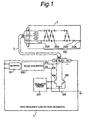
- Such an electrostatic painting device as is schematically described in Fig. 1, consists of a high-frequency low-voltage generator 1, an electrostatic spray gun (electrostatic painting device body) 2, a low-voltage cable 3, an air supplier (which is not shown) and a paint material supplier (which is not shown).
- a high-voltage booster circuit 201 comprises a transformer 202, a multiple voltage rectifier circuit 203, a resistor 204 and an output terminal 205.
- the high-frequency low-voltage generator 1 converts a voltage from a commercial alternating-current power supply to a DC voltage of 12V via a rectifier 101 and DC-DC converter 102.
- the thus obtained DC voltage is supplied to the intermediate point of the primary side coil of the transformer 202 via a line 103 and low-voltage cable 3.
- the ends of the primary side coil are connected to the collectors of transistors 104 and 105 respectively via the low-voltage cable 3 and their emitters are grounded by a common line 106.
- From an oscillation control circuit 107 to the bases of the transistors 104 and 105 are provided driving signals which are in 180-degree phase shift with each other, whereby the transistors 104 and 105 are turned on alternately at frequencies of the driving signals.
- the multiple voltage rectifier circuit 203, resistor 204 and output terminal 205 are connected to the secondary side coil of the transformer 202.
- the transformer 202 boosts the primary side voltage by dozens times, which is further boosted by the multiple voltage rectifier circuit 203 (by ten times in this example) to obtain a DC voltage of - 40kv ⁇ - 90kv.
- the high-voltage booster circuit incorporated in the internal booster-type spray gun has an intrinsic parallel resonance frequency (frequency at which a consumed current becomes minimum: hereafter referred to as an antiresonant frequency) attributable to its unique hardware structure, and when a voltage of such an antiresonant frequency is supplied to a high-voltage booster circuit, power can be converted to high voltages most efficiently.
- an antiresonant frequency frequency at which a consumed current becomes minimum
- power can be converted to high voltages most efficiently.
- a voltage of an antiresonant frequency when a voltage of an antiresonant frequency is supplied, a current consumed at a high-voltage booster circuit is small, whereby a life of a transformer can be maximized while a load to be caused on the spray gun can be minimized.
- efficient utilization of a voltage becomes viable.
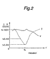
- Fig. 2 is a graph representing a change in current I consumed by a high-voltage booster circuit of an electrostatic spray gun when frequency f of an alternating-current low voltage sent from a high-frequency low-voltage generator to the high-voltage booster circuit is varied and a change in boosted negative DC voltage V.
- the DC voltage V does not change much in the neighborhood of the antiresonant frequency whereas the current I changes significantly.
- the transformer is likely to be damaged by heat. Therefore, it is ideal that the device be driven at driving frequency f 0 at which the consumed current I becomes minimum, that is, about 0.2A.
- Dispersion arising during the manufacture of high voltage booster circuits sometimes results in disadvantageous fluctuation of an intrinsic antiresonant frequency of a high-voltage booster circuit.
- voltage supply from a high-frequency low voltage generator shifts from a high-voltage booster circuit for generating a voltage of, for example, - 40kv to a high-voltage booster circuit for generating a voltage of, for example, - 90kv
- an optimum transmission frequency cannot be specified.
- a technical specification of a high-voltage booster circuit per se is changed, for example, a transformer thereof is improved or modified with a view to cost reduction, etc., an antiresonant frequency specific to the high-voltage booster circuit also changes.
- a volume for adjusting a frequency may be attached to the oscillation control circuit 107 of the high frequency low voltage generator 1 indicated in Fig. 1 to initialize an oscillation frequency at the time of assembly of the high frequency low voltage generator 1.
- an ammeter When antiresonant frequencies specific to high voltage booster circuits disperse, an ammeter is connected to the line 103 of the high frequency low voltage generator 1 and a volume is adjusted by monitoring a current value read by the ammeter to set, as an intrinsic antiresonant frequency, a frequency at which the current value becomes minimum.
- initialization or resetting of a frequency while monitoring an ammeter can be troublesome.
- US-A-5, 703, 770 shows a method and apparatus for generating a high voltage by converting input power at a low voltage to output power at a high voltage, by: supplying input power to a low voltage unit to produce a periodic signal having a frequency; supplying the periodic signal to a rectifier voltage multiplier of a specific type to cause the rectifier voltage multiplier to produce the output power at a high voltage, wherein the ratio of output power to input power is a function of the frequency of the periodic signal; identifying the type of the rectifier voltage multiplier; and continually adjusting the frequency of the periodic signal toward a value which maximizes the ratio of output power to input power.
- US-A-5,939,993 shows method and device for monitoring the production of a high voltage for use in electrostatic application of a coating product, the high voltage being produced by a generator and the monitoring being performed by a circuit for measuring an electrical parameter associated with the high voltage, together with verifying operation of the circuit immediately following start-ups of the generator.
- an object of the present invention to provide an electrostatic painting device with a transmission frequency adjustment device which can automatically adjust a transmission frequency such that a consumed current running in the high voltage booster circuit does not exceed a certain value.
- the frequency control means exercises control for determining a driving frequency to the high voltage booster circuit such that a value of a current detected by the current sensor means becomes a minimum value.
- the current sensor means is installed in the high frequency low voltage generator to detect a current guided to the low voltage cable.
- the frequency control means can operate either when a power switch of the electrostatic painting device is closed or at the set times.
- the electrostatic painting device is further provided with an abnormality indication means for indicating abnormality when a value of a current detected by the current sensor means exceeds a predetermined value.
- the frequency control means adjusts a frequency of a high frequency low voltage when abnormality is indicated.
- Fig. 3 is a schematic system diagram indicating an electrostatic painting device provided with a transmission frequency adjustment device of the present invention.
- the current detection sensor 11 is connected to the line 103 applying a 12V output from the DC-DC converter 102 to the low voltage cable 3.
- the current detection sensor 11 may be a search coil, etc., and anything can be used as the current detection sensor 11 in so far as it can detect a value proportional to a value of a current flowing in the line 103.
- a current flowing in the line 103 is a current on the primary side of the transformer 202 of the high voltage booster circuit 201 and corresponds to a current consumed by the high voltage booster circuit 201.
- a value of a current detected by the current detection sensor 111 is converted to a digital signal by an A/D (analog/digital) converter to be output to the frequency control circuit 112.
- the frequency control circuit 112 stores a frequency adjusting program, in accordance with which a signal of an input current value is processed. If it transpires that the thus processed signal exceeds a threshold, a warning indication signal is output to warning indication means 113. In response to an output of the warning indication signal, the warning indication means 113 turns on a warning lamp and/or sounds alarm.
- the frequency control circuit 112 adjusts an increase/decrease in an oscillation frequency of the oscillation control circuit 107 in accordance with the frequency adjusting program.
- the search start button 114 is connected to the frequency control circuit 112, and when the search start button 114 is operated, a predetermined sub-routine of the frequency adjusting program starts to perform an operation for searching an optimum driving frequency.
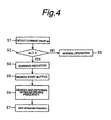
- Fig. 4 is a flow chart depicting a processing operation performed in accordance with the frequency adjusting program stored in the frequency control circuit 112.
- the frequency control circuit 112 receives a current value a 0 detected by the current detection sensor 111.
- the current value a 0 is compared with a threshold A representing a safe driving boundary of the frequency. If the current value a 0 is less than the threshold A, it is determined that the current oscillation frequency of the oscillation control circuit 107 is adequate and the processing operation proceeds to step S3, where the high voltage booster circuit 201 is driven at the current oscillation frequency to operate the electrostatic spray gun.
- step S2 determines whether the current value a 0 has exceeded the threshold A. If it transpires at step S2 that the current value a 0 has exceeded the threshold A, the processing operation proceeds to step S4, where the oscillation control circuit 107 outputs a warning signal to the warning indication means 113 to indicate warning.
- step S5 the processing operation proceeds to step S5, where an operator finds abnormality of a driving frequency from the warning indication and presses the search start button 114 to output a search start signal to the frequency control circuit 112.
- step S6 a frequency adjusting program receives a search start signal and starts an operation for searching an optimum driving frequency.
- the above embodiment employs a manner for obtaining detected current values corresponding to a plurality of driving frequencies to determine an optimum driving frequency.
- the present invention is not limited to the above manner and other known methods for determining an optimum driving frequency such as a method for estimating an optimum driving frequency from a driving frequency - consumed current characteristic curve, at which a current value becomes the smallest, etc. may be employed.
- a processing operation in accordance with the frequency adjusting program may be performed when a power switch of the high-frequency low-voltage generator 1 is closed or at the times pre-set by the oscillation control circuit 107 or when the high voltage booster circuit 201 is exchanged, modified, etc.
- An electrostatic painting device of the present invention is designed such that an optimum frequency at which a minimum consumed current value specific to a high-voltage booster circuit incorporated in the electrostatic painting device or permissible consumed current value is obtained can be automatically generated at a high-frequency low-voltage generator. Therefore, frequencies affected by dispersion arising during manufacture of high voltage booster circuits can be easily adjusted to be an optimum frequency to compensate for manufacturing dispersion. Further, if a new spray gun provided with a high voltage booster circuit of a different voltage specification is employed at a job site, the same high frequency low voltage generator as used for the old spray gun can be employed as it is to readily adjust a frequency of the high voltage booster circuit of the new spray gun to an optimum frequency. Thus, an electrostatic painting device of the present invention is always driven at an optimum frequency, which prolongs a life of the apparatus and improves quality of products manufactured by the apparatus.
- an electrostatic spray gun for atomizing a painting material by compressed air and charging particles of the material is described as an embodiment of an optimum electrostatic painting device.
- the present invention is in no way restricted by the above embodiment and is applicable to, for example, an electrostatic rotary atomization type painting device for discharging a painting material in the form of a thin film from the rim of a cup rotating at a high speed by means of a centrifugal force of the cup and atomizing the material in the form of a thin film by means of repulsion of static electricity instead of utilizing compressed air.
Landscapes
- Electrostatic Spraying Apparatus (AREA)
- Application Of Or Painting With Fluid Materials (AREA)
Description
Claims (6)
- An electrostatic painting device with a transmission frequency adjustment device, comprising
high-voltage booster circuit (201) provided inside the body (2) of the electrostatic painting device to rectify a high-frequency low-voltage and generate a DC high voltage for electrostatic painting,
high-frequency low-voltage generator (1) provided independently of said body (2) of said electrostatic painting device to generate said high-frequency low-voltage,
and a low-voltage cable (3) connecting said high-frequency low-voltage generator (1) to said high-voltage booster circuit (201);
the electrostatic painting device being characterized by comprising:current sensor means (111) for detecting a current value of a primary side of a transformer (202) corresponding to an intrinsic consumed current at said high-voltage booster circuit(201); andfrequency control means (112) for adjusting a frequency of said high-frequency low-voltage in such a manner that a current value detected by said current sensor means (111) does not exceed a prescribed value. - The electrostatic painting device as defined in Claim 1, wherein said frequency control means (112) exercises control to determine a frequency of said high-frequency low-voltage in such a manner that a current value detected by said current sensor means (111) becomes the smallest.
- The electrostatic painting device as defined in Claim 1 or 2, wherein said current sensor means (111) is provided in said high-frequency low-voltage generator to detect a current supplied to said low-voltage cable.
- The electrostatic painting device as defined in Claim 1 or 2, wherein said frequency control means (112) performs an operation for adjusting a frequency of said high-frequency low-voltage when the power switch of the electrostatic painting device is closed.
- The electrostatic painting device as defined in Claim 1 or 2, wherein said frequency control means (112) performs an operation for adjusting a frequency of said high-frequency low-voltage at the set times.
- The electrostatic painting device as defined in one of Claims 1 - 5, further comprising an abnormality indication means (113) for indicating an abnormal state when a current value detected by said current sensor means (111) exceeds a predetermined value, said frequency control means (112) performing an operation for adjusting a frequency of said high-frequency low-voltage when an abnormal state is indicated.
Applications Claiming Priority (3)
| Application Number | Priority Date | Filing Date | Title |
|---|---|---|---|
| JP2000219974A JP2002035647A (en) | 2000-07-21 | 2000-07-21 | Electrostatic coating equipment with power transmission frequency adjustment device |
| JP2000219974 | 2000-07-21 | ||
| PCT/JP2001/006175 WO2002007895A1 (en) | 2000-07-21 | 2001-07-17 | Electrostatic coater with power transmission frequency adjuster |
Publications (3)
| Publication Number | Publication Date |
|---|---|
| EP1222962A1 EP1222962A1 (en) | 2002-07-17 |
| EP1222962A4 EP1222962A4 (en) | 2003-09-17 |
| EP1222962B1 true EP1222962B1 (en) | 2005-03-30 |
Family
ID=18714660
Family Applications (1)
| Application Number | Title | Priority Date | Filing Date |
|---|---|---|---|
| EP01948043A Expired - Lifetime EP1222962B1 (en) | 2000-07-21 | 2001-07-17 | Electrostatic coater with power transmission frequency adjuster |
Country Status (5)
| Country | Link |
|---|---|
| US (1) | US6790285B2 (en) |
| EP (1) | EP1222962B1 (en) |
| JP (1) | JP2002035647A (en) |
| DE (1) | DE60109723T2 (en) |
| WO (1) | WO2002007895A1 (en) |
Cited By (1)
| Publication number | Priority date | Publication date | Assignee | Title |
|---|---|---|---|---|
| JP2002035647A (en) * | 2000-07-21 | 2002-02-05 | Anest Iwata Corp | Electrostatic coating equipment with power transmission frequency adjustment device |
Families Citing this family (15)
| Publication number | Priority date | Publication date | Assignee | Title |
|---|---|---|---|---|
| FR2818463B1 (en) * | 2000-12-18 | 2003-02-28 | Eisenmann France Sarl | HIGH VOLTAGE GENERATOR FOR ELECTROSTATIC PAINT EQUIPMENT |
| EP1797962B1 (en) * | 2004-08-10 | 2012-06-06 | Abb K.K. | Electrostatic coating apparatus |
| US8770496B2 (en) * | 2008-03-10 | 2014-07-08 | Finishing Brands Holdings Inc. | Circuit for displaying the relative voltage at the output electrode of an electrostatically aided coating material atomizer |
| US7926748B2 (en) * | 2008-03-10 | 2011-04-19 | Illinois Tool Works Inc. | Generator for air-powered electrostatically aided coating dispensing device |
| US8016213B2 (en) * | 2008-03-10 | 2011-09-13 | Illinois Tool Works Inc. | Controlling temperature in air-powered electrostatically aided coating material atomizer |
| US8496194B2 (en) | 2008-03-10 | 2013-07-30 | Finishing Brands Holdings Inc. | Method and apparatus for retaining highly torqued fittings in molded resin or polymer housing |
| USD608858S1 (en) | 2008-03-10 | 2010-01-26 | Illinois Tool Works Inc. | Coating material dispensing device |
| US7988075B2 (en) | 2008-03-10 | 2011-08-02 | Illinois Tool Works Inc. | Circuit board configuration for air-powered electrostatically aided coating material atomizer |
| US8590817B2 (en) * | 2008-03-10 | 2013-11-26 | Illinois Tool Works Inc. | Sealed electrical source for air-powered electrostatic atomizing and dispensing device |
| US7918409B2 (en) * | 2008-04-09 | 2011-04-05 | Illinois Tool Works Inc. | Multiple charging electrode |
| US8154891B1 (en) * | 2008-05-19 | 2012-04-10 | Raytheon Company | Methods and apparatus for selectable output DC/DC converter |
| US8225968B2 (en) | 2009-05-12 | 2012-07-24 | Illinois Tool Works Inc. | Seal system for gear pumps |
| JP6890978B2 (en) * | 2017-01-11 | 2021-06-18 | 日本電波株式会社 | High voltage power supply for electrostatic coating equipment |
| JP6856833B2 (en) * | 2017-01-25 | 2021-04-14 | 日本電波株式会社 | High voltage controller |
| CN113396969B (en) * | 2021-05-26 | 2022-09-16 | 江苏大学 | Flexible electrostatic spraying equipment and method based on fruit electrical characteristics |
Family Cites Families (10)
| Publication number | Priority date | Publication date | Assignee | Title |
|---|---|---|---|---|
| JPS6355792U (en) * | 1986-09-26 | 1988-04-14 | ||
| JPH0757330B2 (en) * | 1990-10-23 | 1995-06-21 | 旭サナック株式会社 | Spark prevention device in electrostatic coating equipment |
| DE4232026C2 (en) * | 1992-09-24 | 1996-10-24 | Wagner Int | Electrostatic coating gun and method for generating a high voltage |
| EP0626208B2 (en) * | 1993-04-08 | 2004-09-29 | Nordson Corporation | Power supply for an electrostatic spray gun |
| JP2596595Y2 (en) * | 1993-05-26 | 1999-06-14 | 菊水電子工業株式会社 | Parallel resonant converter |
| FR2724786B1 (en) * | 1994-09-16 | 1996-12-20 | Sames Sa | HIGH-VOLTAGE PROCESS AND DEVICE, PARTICULARLY FOR THE ELECTROSTATIC APPLICATION OF COATING PRODUCTS |
| FR2736773B1 (en) * | 1995-07-10 | 1997-08-22 | Sames Sa | HIGH-VOLTAGE PROCESSING PROCESS AND ELECTROSTATIC PROJECTION DEVICE OF COATING PRODUCT |
| JP3530323B2 (en) * | 1996-10-28 | 2004-05-24 | オリジン電気株式会社 | DC high voltage generator for electrostatic coating |
| JPH10202151A (en) * | 1997-01-08 | 1998-08-04 | Illinois Tool Works Inc <Itw> | Electrostatic coating system and method |
| JP2002035647A (en) * | 2000-07-21 | 2002-02-05 | Anest Iwata Corp | Electrostatic coating equipment with power transmission frequency adjustment device |
-
2000
- 2000-07-21 JP JP2000219974A patent/JP2002035647A/en active Pending
-
2001
- 2001-07-17 WO PCT/JP2001/006175 patent/WO2002007895A1/en not_active Ceased
- 2001-07-17 DE DE60109723T patent/DE60109723T2/en not_active Expired - Fee Related
- 2001-07-17 EP EP01948043A patent/EP1222962B1/en not_active Expired - Lifetime
- 2001-07-17 US US10/070,924 patent/US6790285B2/en not_active Expired - Fee Related
Cited By (1)
| Publication number | Priority date | Publication date | Assignee | Title |
|---|---|---|---|---|
| JP2002035647A (en) * | 2000-07-21 | 2002-02-05 | Anest Iwata Corp | Electrostatic coating equipment with power transmission frequency adjustment device |
Also Published As
| Publication number | Publication date |
|---|---|
| WO2002007895A1 (en) | 2002-01-31 |
| JP2002035647A (en) | 2002-02-05 |
| EP1222962A4 (en) | 2003-09-17 |
| EP1222962A1 (en) | 2002-07-17 |
| US20020148405A1 (en) | 2002-10-17 |
| DE60109723D1 (en) | 2005-05-04 |
| DE60109723T2 (en) | 2006-02-09 |
| US6790285B2 (en) | 2004-09-14 |
Similar Documents
| Publication | Publication Date | Title |
|---|---|---|
| US6790285B2 (en) | Electrostatic coater with power transmission frequency adjuster | |
| Lahyani et al. | Failure prediction of electrolytic capacitors during operation of a switchmode power supply | |
| US9662669B2 (en) | Electrostatic coating apparatus | |
| CN103001496B (en) | Switch power supply and image processing system | |
| HU203994B (en) | Electronical high voltage generator for electrostatic atomizers | |
| US6924627B1 (en) | Method of reactive power regulation and aparatus for producing electrical energy in an electrical network | |
| JP4111348B2 (en) | Static eliminator | |
| US5812905A (en) | Method and apparatus for controlling a charge voltage of an OPC drum to be an optimum value | |
| JPS63178718A (en) | High voltage generator and method for protecting the generator from electric arc | |
| KR20060103404A (en) | Method of arc detection | |
| CA2171253C (en) | Electrostatic spray-coating apparatus | |
| US5703770A (en) | Method and apparatus for generating a high voltage | |
| JP5559457B2 (en) | Piezoelectric transformer type high voltage power supply device and image forming apparatus | |
| US5939993A (en) | Method for developing a high voltage and device for electrostatic coating product spraying | |
| JP4638976B2 (en) | Spray painting equipment | |
| JP3328393B2 (en) | Electrostatic powder coating gun and high voltage generation method | |
| KR100243126B1 (en) | Method for controlling transfer voltage of an image forming apparatus and an apparatus thereof | |
| JP2018121436A (en) | High voltage control device | |
| JPS6150310B2 (en) | ||
| JP2001025249A (en) | High voltage generator | |
| US20020191357A1 (en) | Current regulated voltage limited high voltage power supply for corona charger | |
| JP6890978B2 (en) | High voltage power supply for electrostatic coating equipment | |
| JP3396017B2 (en) | Piezoelectric transformer DC power supply | |
| JPH0663507A (en) | Piezoelectric vibrator driving circuit | |
| US4374346A (en) | Voltage detection circuits for a-c power supplies |
Legal Events
| Date | Code | Title | Description |
|---|---|---|---|
| PUAI | Public reference made under article 153(3) epc to a published international application that has entered the european phase |
Free format text: ORIGINAL CODE: 0009012 |
|
| 17P | Request for examination filed |
Effective date: 20020403 |
|
| AK | Designated contracting states |
Kind code of ref document: A1 Designated state(s): DE FR GB |
|
| A4 | Supplementary search report drawn up and despatched |
Effective date: 20030801 |
|
| 17Q | First examination report despatched |
Effective date: 20031202 |
|
| GRAP | Despatch of communication of intention to grant a patent |
Free format text: ORIGINAL CODE: EPIDOSNIGR1 |
|
| GRAS | Grant fee paid |
Free format text: ORIGINAL CODE: EPIDOSNIGR3 |
|
| GRAA | (expected) grant |
Free format text: ORIGINAL CODE: 0009210 |
|
| AK | Designated contracting states |
Kind code of ref document: B1 Designated state(s): DE FR GB |
|
| REG | Reference to a national code |
Ref country code: GB Ref legal event code: FG4D |
|
| REF | Corresponds to: |
Ref document number: 60109723 Country of ref document: DE Date of ref document: 20050504 Kind code of ref document: P |
|
| PLBI | Opposition filed |
Free format text: ORIGINAL CODE: 0009260 |
|
| PLAX | Notice of opposition and request to file observation + time limit sent |
Free format text: ORIGINAL CODE: EPIDOSNOBS2 |
|
| 26 | Opposition filed |
Opponent name: J. WAGNER AG Effective date: 20051230 |
|
| ET | Fr: translation filed | ||
| PLAF | Information modified related to communication of a notice of opposition and request to file observations + time limit |
Free format text: ORIGINAL CODE: EPIDOSCOBS2 |
|
| PLBB | Reply of patent proprietor to notice(s) of opposition received |
Free format text: ORIGINAL CODE: EPIDOSNOBS3 |
|
| PLAB | Opposition data, opponent's data or that of the opponent's representative modified |
Free format text: ORIGINAL CODE: 0009299OPPO |
|
| R26 | Opposition filed (corrected) |
Opponent name: J. WAGNER AG Effective date: 20051230 |
|
| PLCK | Communication despatched that opposition was rejected |
Free format text: ORIGINAL CODE: EPIDOSNREJ1 |
|
| PLBN | Opposition rejected |
Free format text: ORIGINAL CODE: 0009273 |
|
| STAA | Information on the status of an ep patent application or granted ep patent |
Free format text: STATUS: OPPOSITION REJECTED |
|
| 27O | Opposition rejected |
Effective date: 20080626 |
|
| PGFP | Annual fee paid to national office [announced via postgrant information from national office to epo] |
Ref country code: FR Payment date: 20090729 Year of fee payment: 9 |
|
| PGFP | Annual fee paid to national office [announced via postgrant information from national office to epo] |
Ref country code: DE Payment date: 20090821 Year of fee payment: 9 Ref country code: GB Payment date: 20090730 Year of fee payment: 9 |
|
| GBPC | Gb: european patent ceased through non-payment of renewal fee |
Effective date: 20100717 |
|
| REG | Reference to a national code |
Ref country code: FR Ref legal event code: ST Effective date: 20110331 |
|
| PG25 | Lapsed in a contracting state [announced via postgrant information from national office to epo] |
Ref country code: DE Free format text: LAPSE BECAUSE OF NON-PAYMENT OF DUE FEES Effective date: 20110201 |
|
| REG | Reference to a national code |
Ref country code: DE Ref legal event code: R119 Ref document number: 60109723 Country of ref document: DE Effective date: 20110201 |
|
| PG25 | Lapsed in a contracting state [announced via postgrant information from national office to epo] |
Ref country code: FR Free format text: LAPSE BECAUSE OF NON-PAYMENT OF DUE FEES Effective date: 20100802 |
|
| PG25 | Lapsed in a contracting state [announced via postgrant information from national office to epo] |
Ref country code: GB Free format text: LAPSE BECAUSE OF NON-PAYMENT OF DUE FEES Effective date: 20100717 |