Technical Field
The present invention relates to a compression molded
product, more particularly to a compression molded product
having an outer shell with an abrasion resistance, and to a method
for producing such a compression molded product.
Further, the present invention relates to a compression
molded product, more specifically to a compression molded
product in which viable bacteria are contained without any
damages and the surface of the compression molded product has
an abrasion resistance, and to a method for producing such a
compression molded product.
Furthermore, the present invention relates to a compression
molded product, more specifically to a compression molded
product in which microcapsules are contained without any damages
and the surface of the compression molded product has an
attrition resistance, and to a method for producing such a
compression molding material.
Background Art
Tablets are handy for carrying and easy for dosing as
compared to injection drugs and other pharmaceutical drugs.
Therefore, the form of tablets is widely used for medicament
containing active ingredient or food dosage form which contains
some ingredients good for health, viable bacteria such as
acidophilus, chlorella, beta-carotene, or several vitamins or
some ingredient for nutritional supplement.
Such tablets are generally produced by compressing a molding
material by a tabletting machine.
In case of compressing a molding material, a lubricant is
added in the material for the purpose of preventing tabletting
problems such as sticking, laminating and capping caused when
the molding material attaches on material contacting surfaces
of a die, a lower punch and an upper punch of the tabletting
machine and preventing grinding of the die, the lower punch and
the upper punch of the tabletting machine when the molding
material is compressed.
Stearic acid, stearic acid metal salt such as magnesium
stearate and calcium stearate are used as a lubricant for
producing pharmaceutical tablets. Sucrose esters of fatty acid
powders, glycerine fatty acid ester powders, and hardened oil
are used for producing food tablets.
An internal lubrication method is generally used for
producing tablets by compressing a molding material in which
a lubricant is added in advance.
Chewable tablets are widely used for pharmaceutical tablets
and food tablets considering ease of dosing, because they may
be taken with water or without water, namely by chewing in the
oral cavity to be dissolved with a saliva.
However, tablets are produced by such an internal
lubrication method, a relatively large amount of lubricant
should be added in the molding material so as to prevent the
molding material from adhering on each material contacting
surface of the die, upper punch and lower punch of the tabletting
machine.
If a lubricant is added considerably, the dissolving time
and disintegration time of the tablets become slow because of
the repellency of the lubricant, thereby causing problems such
as deteriorated absorption in the body and delayed appearance
of the effect.
Further, if the tablets are uncoated tablets, there has been
a problem that the surfaces of tablets apt to be chipped by the
vibration applied on the tablets from outside in case of storage
or transportation.
In particular the surfaces of the tablets are easily chipped
when they are packed in a bottle.
For preventing such a chip, it is generally considered that
shells such as sugar coatings, glue coatings and film coatings
are applied on the surfaces of the tablets (uncoated tablets)
produced by compression using a coating machine. However, for
this purpose, a coating process is further required to be added
to a compression process of the molding material of a tablet
production process. Further, if coatings are executed, such
tablets can't be called naked tablets.
For example, if coated chewable tablets are chewed in the
oral cavity, tastes of the outer shell and the inner shell are
noticeably different or some of the outer shell are remained
in the mouth, thereby making a person uncomfortable. Therefore,
uncoated tablets are desired.
Further, the lubricant becomes a cause of bitter taste
because of its hydrophobic property.
Therefore, the chewable tablets produced by the prior
internal lubrication method arise a problem of bitter taste
caused by the lubricant contained in the tablet when they are
chewed in the mouth.
Recently viable bacteria containing tablets (compression
molded product) including viable bacteria such as
bifidobacteria, acidophilus and yeast have been developed using
a freeze dry technology.
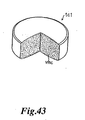
Fig.43 is a perspective view diagrammatically showing one
embodiment of a prior viable bacteria containing tablet of which
one part is cutaway.
Viable bacteria vmc··· are dispersed in the tablet tc1.
According to such a viable bacteria containing tablet tc1,
viable bacteria vmc··· are of course contained in the molding
material to be compressed. If the molding material including
viable bacteria vmc··· is compressed by means of dies and punches,
the force of compression is applied on the viable bacteria vmc···
and a part of them contained in the tablet tc1 is damaged to
be annihilated.
In order to solve the above-mentioned problems, chlorella
powders are used as an excipient so as to have practical hardness
of the produced tablets when the molding material including
viable bacteria is tabletted (compressed) at a low pressure (see
JP-A-8-80007).
A method using magnesium aluminometasilicate, calcium
citrate or calcium dihydrogen phosphate as an excipient has been
already proposed (see JP-A-8-143463).
Further a method using a saccharide (mannitol, lactose,
sucrose, glucose, galactose or fructose) as an excipient has
been also proposed (see JP-B-6-53658).
However, even if the molding material including viable
bacteria is tabletted (compressed) at a low pressure, it can't
be avoided that the viable bacteria vmc included in the molding
material are annihilated by the compression force applied on
the molding material.
Furthermore, if an excipient is devised, tablets
(compression molded products) produced at a low pressure are
apt to be chipped or worn away during storage or transportation.
In order to prevent extinction of viable bacteria vmc
contained in the molding material by devising an excipient, the
material of an excipient is limited and its selection range
becomes small in case of producing viable bacteria containing
tablets.
Recently, several types of tablets (compression molded
product) have been developed applying DDS (Drug Delivery
System).
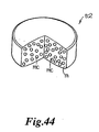
Fig.44 is a perspective view of one embodiment of a prior
microcapsule containing tablet of which one part is cutaway.
The tablet tc2 is generally called as a spacetab in which
microcapsules mc··· are dispersed in the matrix m (connected
part).
Fig.45 is a sectional view diagrammatically showing
microcapsule mc.
Liquid lipid micro dews d··· are contained to be pulverized
as powders in an inclusion matrix.
The tablet tc2 including microcapsules mc has some
advantages, for example, control-releasing so as to release
slowly at the targeting rate hydrophobic perfume ingredient or
physiologically active substance dissolved in the liquid lipid
micro dews d···, improvement of storage of micro dews d··· which
are dispersed in a microcapsule mc as the result of preventing
oxidation of lipid which comprises the micro dews d··· as the
result in making the inclusion matrix mp use of a barrier for
the movement of oxygen, masking of bitter taste so that the bitter
ingredient does not stimulate taste bud directly in the result
in enclosing such bitter ingredient of the physiological active
ingredient or dews d··· in the inclusion matrix mp, in case the
physiological active ingredient which is dissolved in the liquid
lipid dew d··· or the dew d··· has bitter taste in themselves,
good carriage to the targeting intestinal absorption part by
preventing the physiological active ingredient from dissolving
by digestive enzyme with lipid, when the tablet tc2 is
administered, when the physiological active ingredient is
dissolved in the lipid which comprises the micro dews d··· which
are dispersed in the microcapsules mc, or, improvement of
handling a molding material in case of producing tablet in the
result that the lipid with viscidity property is powdered by
encapsulation. As mentioned above, the tablets tc2 are widely
used in the field of drugs including several types of active
agents and in the field of foods (for example health foods and
specified health foods).
However, when such tablets tc2 are produced, microcapsules
mc··· are naturally contained in the molding material to be
compressed. If such a material is compressed with the die and
the punches, the compression force applied on the material is
also applied on the microcapsules mc··· contained in the molding
material so that the microcapsules mc··· are damaged. If micro
dews d··· contained in the microcapsule mc is liquid such as
beta-carotene, the liquid is run out of the capsule mc and
oxidized, thereby deteriorating its potency.
In order to solve the above-mentioned problems, even if a
molding material using chlorella powders as an excipient is
tabletted (compressed) at a low pressure, all kinds of things
to give a practical hardness to the tablets are done in the prior
arts (see JP-A-8-80007).
A method using magnesium aluminometasilicate, calcium
citrate or calcium dihydrogen phosphate as an excipient has been
already proposed (see JP-A-8-143463).
Further a method using a saccharide (mannitol, lactose,
sucrose, glucose, galactose or fructose) as an excipient has
been also proposed (see JP-B-6-53658).
Furthermore, if an excipient is devised, tablets
(compressed product) produced at a low pressure are apt to be
chipped or worn away.
Disclosure of the Invention
The first object of the present invention to solve the
above-mentioned problems is to provide a compression molded
product which doesn't make its dissolving time and
disintegration time prolong, doesn't cause the tablet surface
to be chipped during storage or transportation, and doesn't give
harsh flavor when the tablet is chewed in the mouth and also
to provide a method for producing such a compression molded
product.
The second object of the present invention is to provide
a compression molded product including viable bacteria which
doesn't use a special excipient, doesn't cause damages on the
viable bacteria vmc··· included in the molding material when
normal tabletting pressure is applied, and further doesn't cause
chipping or wear-out of tablets (compression molded product)
during storage or transportation and to provide a method for
producing such a compression molded product.
The inventors of the present invention have found that the
viable bacteria vmc··· contained in a tablet are damaged even
if a molding material including viable bacteria vmc··· is
tabletted (compressed) at a low pressure and also have found
that there are any causes of damages on the viable bacteria other
than the tabletting pressure applied on the molding material.
The inventors have worked out the means to solve the
above-mentioned problems for a long time and have found that
one of the reasons generating damages on the viable bacteria
vmc··· even at a low tabletting pressure exists in a lubricant
contained in the molding material.
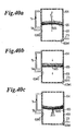
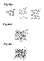
Fig.46 explains how damages are generated on the viable
bacteria vmc··· contained in the molding material to be
compressed at a low tabletting pressure.
For producing tablets (compression molded products)
including viable bacteria vmc···, viable bacteria vmc···, an
excipient V, a lubricant L and other materials (not shown) if
required are prepared as shown in Fig.46a and then they are mixed
to be a molding material M (see Fig.46b).
The lubricant L is added in the molding material for
preventing the molding material from adhering on a die surface
(inner circumferential wall), a lower punch surface (upper face)
and an upper punch surface (lower face), preventing the produced
tablets (compression molded product) from causing tabletting
problems such as sticking, laminating and capping and preventing
the dies, the upper punches and the lower punches from grinding.
A great deal of lubricant L is added in the molding material
M.
Stearic acid, stearic acid metal salt (Al, Mg, K, Ca, Na)
are often used as a lubricant for producing pharmaceutical
tablets (compression molded product). Sucrose fatty acid ester
is often used as a lubricant for producing food tablets
(compression molded product).
Thus produced molding material M is sequentially tabletted
(compressed) by means of the dies, the lower punch and the upper
punch of the tabletting machine to produce a tablet (compression
molded product).
In this compression and molding process, the molding
material to be tabletted takes on heat during compression. When
the lubricant L contained in the molding material is melted by
this heat to cause the melted lubricant L adhere to the viable
bacteria vmc··· and the excipient V··· around thereof and cause
the lubricant L adhere each other.
Tabletting (compression) of the molding material M is
processed under such a condition, damages are caused for the
viable bacteria vmc··· contained in the molding material.
When the viable bacteria vmc··· are thus damaged, the
survival rate of the viable bacteria vmc··· in the tablet tc are
reduced.
The inventors of the present invention have found that if
the lubricant L isn't added in the molding material, the viable
bacteria vmc··· aren't damaged when the molding material is
tabletted (compressed) with a normal tabletting pressure. And
further if a lubricant which is dissolved by the heat caused
by the molding material under tabletting is applyed on the die
surface (inner circumferential wall), the lower punch surface
(upper face) and the upper punch surface (lower face) and a
molding material excluding a lubricant and including viable
bacteria is tabletted (compressed) by means of such lubricated
dies, lower punches and upper punches. The molding material
isn't adhered to the die surface, the upper punch surface and
the lower punch surface, thus preventing tabletting problems
such as sticking, laminating and capping of the produced tablets
(compression molded product) and preventing grinding of the dies,
the lower punch and the upper punch, thereby they have found
that tablets including viable bacteria can be produced at high
productivity and melted lubricant is transferred on the tablet
surface to make an outer shell having wear resistance on the
tablet surface.
The third object of the present invention is to provide a
microcapsule containing compression molded product wherein a
general excipient is used, microcapsules mc··· contained in the
molding material aren't damaged when normal tabletting pressure
is applied, and tablets (compression molded product) aren't
chipped or worn out during storage or transportation and to
provide a method for producing such a microcapsule containing
compression molded product.
The inventors of the present invention have found that the
microcapsules mc··· contained in a tablet are damaged even if
a molding material including the microcapsules mc··· is
tabletted (compressed) at a low pressure and also have found
that there are any causes of damages on the microcapsules mc···
other than the tabletting pressure applied on the molding
material.
The inventors have worked out the means to solve the
above-mentioned problems for a long time and have found that
one of the reasons generating damages on the microcapsules mc···
even at a low tabletting pressure exists in a lubricant contained
in the molding material.
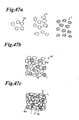
Fig.47 explains how damages are generated on the
microcapsules mc··· contained in the molding material to be
compressed at a low tabletting pressure.
For producing tablets (compression molded product)
including microcapsules mc···, microcapsules mc···, an excipient
V, a lubricant L and other materials (not shown) if required
are prepared as shown in Fig.47a and then they are mixed to be
a molding material M (see Fig.47b).
The lubricant L is added in the molding material for
preventing the molding material from adhering on a die surface
(inner circumferential wall), a lower punch surface (upper face)
and an upper punch surface, preventing the produced tablets
(compression molded product) from causing tabletting problems
such as sticking, laminating and capping and preventing the dies,
the upper punches and the lower punches from grinding. A great
deal of lubricant L is added in the molding material M.
Stearic acid, stearic acid metal salt (Al, Mg, K, Ca, Na)
are often used as a lubricant for producing pharmaceutical
tablets (compression molded product). Sucrose fatty acid ester
is often used as a lubricant for producing food tablets
(compression molded product).
Thus produced molding material M is sequentially tabletted
(compressed) by means of the dies, the lower punch and the upper
punch of the tabletting machine to produce a tablet (compression
molded product).
In this compression and molding process, the molding
material to be tabletted takes on heat during compression and
the lubricant L contained in the molding material is melted to
cause the melted lubricant L adhere to the microcapsules mc···
and the excipient V··· around thereof and cause the lubricant
L adhere each other.
Tabletting (compression) of the molding material is
processed under such a condition, damages are caused for the
microcapsules mc··· contained in the molding material (see
Fig.47c).
The inventors of the present invention have found that if
the lubricant L isn't added in the molding material, the
microcapsules mc··· aren't damaged when the molding material is
tabletted (compressed) with a normal tabletting pressure. And
further if a lubricant which is dissolved by the heat caused
by the molding material under tabletting is applyed on the die
surface (inner circumferential wall), the lower punch surface
(upper face) and the upper punch surface (lower face) and a
molding material excluding a lubricant and including
microcapsules is tabletted (compressed) by means of such
lubricated dies, lower punches and upper punches. The molding
material isn't adhered to the die surface, the upper punch
surface and the lower punch surface, thus preventing tabletting
problems such as sticking, laminating and capping of the
produced tablets (compression molded product) and preventing
grinding of the dies, the lower punch and the upper punch, thereby
they have found that tablets including microcapsules can be
produced at high productivity and the melted lubricant is
transferred on the tablet surface to make an outer shell having
wear resistance on the tablet surface.
According to one aspect of the present invention, a
compression molded product is constructed with a compression
molded product body and an outer shell provided on the surface
of the body and the outer shell at least includes a part where
at least the outer shell material powders thermally melted are
solidified each other.
The term "compression molded product" used in the
specification of the present invention includes oral
administration type tablets and also tablets other than oral
administration type and includes medical tablets and food
tablets such as nutritional supplements. Also the term includes
tablets for human being and for animals and agriculture.
Further "compression molded product" includes uncoated
tablets, chewable tablets, foaming tablets and long active
tablets.
The term "thermally melted" used in the specification of
the present invention means being melted thermally by the heat
generated when a molding material is compressed with the die,
the lower punch and the upper punch.
The phrase "the outer shell at least includes a part where
the outer shell material powders are solidified each other"
means that the outer shell material powders thermally melted
at the outer shell formed on the surface of the compression molded
product body are solidified each other. As far as there are
any parts where the thermally melted outer shell material
powders are solidified, this invention includes the compression
molded product in which the surface of the compression molded
product body is formed with the outer shell further including
a part where thermally melted outer shell material powders and
not thermally melted outer shell material powders are solidified,
and the compression molded product in which the outer shell
further including where thermally melted outer shell material
powders are solidified to the particles comprising the
compression molded product body is formed on the surface of the
compression molded product body.
If the compression molded product is medical tablets, animal
drug tablets and agricultural chemical tablets, several
materials such as active ingredients, excipient such as lactose,
supplements and adjuvant may be included in the "compression
molded product body" but lubricants aren't preferably included.
It is because lubricants aren't required to be contained
in the molding material and they are required to exist between
the molding material to be compressed and the material
contacting surfaces of the dies, the lower punches and the upper
punches in order to prevent the molding material adhering to
those surfaces. Further, if lubricant powders are added, the
dissolving time and disintegration time of the tablets are
delayed because of the water repellency of the lubricant so that
absorption into the human body is deteriorated or appearance
of effect is delayed.
Further, if the compression molded product is a chewable
tablet, when the tablet is chewed and dissolved with the saliva
in the mouth, a person dosing the tablet feels unpleasant taste
(bitter taste) because of the water repellency of the lubricant
if lubricant powders are included in the compression molded
product body.
In addition, the "compression molded product body" may
preferably include components which are considered to be good
for health like viable bacteria such as acidophilus (freeze dry
pulverized product), chlorella (freeze dry pulverized product),
beta-carotene, and several kinds of vitamin; nutritional
supplements; excipients such as a saccharide like mannitol and
sugar alcohol; supplements; and adjuvants, but may not include
sucrose esters of fatty acid powders, glycerine fatty acid ester
powders, hydrogenate oil and fat when the compression molded
product is food tablets.
Such food tablets which may be swallowed together with water
or may be chewable tablets chewed to be dissolved with saliva
in the mouth without requiring water. If sucrose esters of fatty
acid powders, glycerine fatty acid ester powders, hydrogenate
oil and fat powders are added, the dissolving time and
disintegration time of the compression molded product are
delayed because of their repellency, thereby deteriorating
absorption of the component which is considered to be good for
health and the active ingredients of nutritional supplement into
the human body and delaying the appearance of effects.
Several kinds of "outer shell material powders" may be used,
but a material which has a function of a lubricant and generates
thermofusion caused in case of compression of the molding
material with the die, the lower punch and the upper punch is
preferable.
The particle diameter of the "outer shell material powders"
isn't specifically limited, but it may be preferably a little
larger than that of the lubricant powders added in the molding
material. Namely, the particle diameter of the outer shell
material powders is preferably within the range of 5µm to 50
µm, more preferably from 10µm to 20µm, furthermore preferably
from 10µm to 15µm.
It is because if the outer shell material powders having
too little particle diameter are used, the outer shell is
constructed to be too dense after a part of the powders is
thermally melted to form an outer shell, therefore the
physicality of the compression molded product body and that of
the outer shell are considerably different and the
characteristic as an uncoated tablets is damaged.
Further, if the outer shell material powders having too
large particle diameter are used, the surface of the compression
molded product becomes coarse to make the wear resistance of
the outer shell damaged.
According to the compression molded product of the present
invention, the outer shell including a part where the outer shell
material powders are thermally melted and the thermally melted
powders are solidified each other is formed thereon, thereby
hardly causing chipping during storage or transportation.
On the other hand, the outer shell formed on the compression
molded product body is constructed with so as to include a part
where thermally melted outer shell material powders are
solidified each other. Comparing with the tablets having shells
formed by spraying a coating liquid on the surface of the uncoated
tablets, the tablets of the present invention are fragile and
are easily destroyed when they are chewed in the mouth.
Therefore, there is no uncomfortable feeling caused by the
difference of physical properties of the compression molded
product body (tablet body) and the outer shell when the tablet
is chewed in the mouth and the tablet is like a naked tablet,
thereby such a tablet is suitable for a chewable tablet.
Furthermore, only the outer shell is formed on the surface
of the compression molded product so that such product has a
rapid dissolving time and disintegration time and can be
immediately dissolved in a desired part if a lubricant isn't
included in the compression molded product body.
Therefore, such a compression molded product is rapidly
absorbed in the human body and has a rapid action if a lubricant
isn't contained.
Still further, if such a compression molded product is a
chewable tablet without including a lubricant in the compression
molded product body, the chewable tablet doesn't give unpleasant
taste (bitter taste) to a person chewing the tablet in the mouth
because a lubricant isn't included.
According to another aspect of the present invention, the
outer shell has an abrasion resistance.
The term "abrasion resistance" means that the technical
range of the present invention includes a compression molded
product of which shell has a higher hardness than the compression
molded product body as far as outer shell material powders are
thermally melted to be solidified each other at least at a part
of the compression molded product body surface.
According to such a compression molded product, the outer
shell including a part where the outer shell material powders
are thermally melted to be solidified each other has abrasion
resistance, thereby preventing chipping during storage or
transportation.
According to still another aspect of the present invention,
the outer shell material powders have a function of a lubricant,
and they are powders at a room temperature and are melted by
the heat generated when the compression molding step is
executed.
Because the outer shell material powders of the compression
molded product has a function of lubricant, if they are applied
on the die surface, the upper punch surface and the lower punch
surface in case of producing the compression molded product,
the compression molded product doesn't have tabletting
problems.
In addition, they are powders in a room temperature, thereby
achieving an abrasion resistance after being formed into the
outer shell.
According to still another aspect of the present invention,
a melting point of the outer shell material powders is greater
than or equal to 30°C and less than or equal to 80°C.
More preferably, it is greater than or equal to 40°C and less
than or equal to 78°C.
The heat generated in case of compressing the material by
means of dies, lower punches and upper punches varies depending
on the tabletting pressure of compression, the amount of
material to be molded, and the component and composition of the
molding material. However, the dies, lower punches and upper
punches generate heat from 30°C to 80°C in case of tabletting.
Accordingly, if the outer shell material powders having a
melting point (m.p.) in the above-mentioned temperature range,
the outer shell including a part where a part of the outer shell
material powders is thermally melted and the thermally melted
powders are solidified each other on the compression molded
product body surface is formed.
The outer shell formed on the compression molded product
body surface doesn't melt less than 30°C so that it is solid at
a room temperature (1°C~30°C) and cool place (less than 15°C),
thereby preventing chipping of the compression molded product
surface in case of storage or transportation.
When such a compression molded product having relatively
low melting point of the outer shell material powder within the
above-mentioned range is taken in the mouth, the outer shell
quickly melts therein like an uncoated tablet so that it can
be used as a chewable tablet.
According to another aspect of the present invention, the
outer shell material powders are powders selected from a group
consisting of fatty acid, fatty acid metallic salt and fatty
acid ester.
There are sucrose esters of fatty acid and glycerine fatty
acid ester as fatty acid ester.
There are a saccharide like glucose and sucrose, a sugar
alcohol like sorbitol and mannitol as a sugar of sucrose esters
of fatty acid.
Further there is saturated fatty acid of which carbon number
is equal to or more than 12 and equal to or less than 22 such
as dodecanoic acid, tridecanoic acid, tetradecanoic acid,
pentadecanic acid, hexadecanoic acid, heptadecanic acid,
octadecanoic acid (stearic acid), nonadecylic acid, icosanic
acid, henicosanic acid, docosanic acid (their melting points
(m.p) are within the range of 44.2°C to 79.9°C) as fatty acid
component of fatty acid, fatty acid metal salt or sucrose esters
of fatty acid.
Metal salt component of fatty acid metal salt is for example
aluminum (Al), sodium (Na), pottasium (K), calcium (Ca), and
magnesium (Mg).
Specifically, there is stearic acid metal salt (Al, Na, K,
Ca, Mg) as fatty acid metal salt.
Sucrose esters of fatty acid has the melting point (m.p.)
of within the range of about 52°C to 62°C, is superior in safety,
is easily obtainable and achieves excellent abrasion resistance
function as an outer shell, thereby being suitable for the shell
material.
Further glycerine fatty acid ester has the melting point
(m.p.) of within the range of about 62°C to 68°C, is superior
in safety, is easily obtainable and achieves excellent abrasion
resistance function as an outer shell, thereby being suitable
for the shell material.
Furthermore, hydrogenate oil and fat has the melting point
(m.p.) of within the range of about 40°C to 48°C, is superior
in safety, is easily obtainable and achieves excellent abrasion
resistance function as an outer shell, thereby being suitable
for the shell material.
Still further, stearic acid has the melting point (m.p.)
of within the range of about 56°C to 72°C, is superior in safety,
is easily obtainable and achieves excellent abrasion resistance
function as an outer shell, thereby being suitable for the shell
material.
Because sucrose esters of fatty acid, glycerine fatty acid
ester, hydrogenate oil and fat and stearic acid have a function
of lubricant (molding lubricant), when a molding material is
compressed using dies, upper punches and lower punches on which
material contacting surfaces are applied with them, the molding
material doesn't adhere on the surfaces because they functions
as a lubricant. As a result, frequency of tabletting problems
such as sticking, laminating and capping is reduced when the
compression molded product is produced, thereby achieving high
productivity (industrially profitable).
According to such a compression molded product, the outer
shell material powders which are superior in safety, are easily
obtainable, bring out abrasion resistance and function as a
lubricant are used so that such a product has advantages such
that it is superior in safety, hardly causes chipping on the
surface and is easily produced.
Further, if a large amount of sucrose esters of fatty acid,
glycerine fatty acid ester powders, hydrogenate oil and fat is
taken in, there is no problem, therefore, they can be used as
a shell material of medical tablets and food tablets without
considering the intake amount a day. However, if stearic acid
is used, it isn't required to consider the intake amount a day
if it is used for medical tablets of which amount taken per a
day is just a little, but it is necessary to observe the intake
amount doesn't exceed the maximum amount a day if it is used
for food tablets because they are taken 50 tablets or 100 tablets
per day.
According to another aspect of the present invention, the
compression molded product body includes viable bacteria and
pharmaceutical powders, and the pharmaceutical powders are
substantially comprising pharmaceutical powders having a higher
melting point than the heat generated when the compression
molding step is executed.
The term "viable bacteria" means powders in which effective
enteric bacteria such as lactic acid bacteria and bifidobacteria
and effective bacteria such as bacillus natto and are
freeze-dried and pulverized.
The "pharmaceutical powders having a higher melting point
than the heat generated when the compression molding step is
executed" are preferably made of a powdered or granular material
of which melting point is equal to or larger than 50°C, more
preferably above 70°C, and still more preferably above 80°C.
The phrase "substantially comprising pharmaceutical
powders having a higher melting point than the heat generated
when the compression molding step is executed" means that a
minute amount of powders having a lower melting point than the
above-mentioned range may be added in the pharmaceutical
powders.
According to the compression molded product (viable
bacteria containing compression molded product), because the
pharmaceutical powders are substantially comprised of a
material having higher melting point than the heat generated
at a time of compression molding, the component which melts by
the heat generated at a time of compression isn't included in
the pharmaceutical powders. As a result, the viable bacteria
contained in the compression molded product (viable bacteria
containing tablet), are hardly damaged.
Consequently, the compression molded product (viable
bacteria containing tablet) has a higher effectiveness because
the survival rate of the viable bacteria in the tablet is high.
Further, the outer shell including a part where the outer
shell material powders are thermally melted to be solidified
each other is formed on the surface, thereby hardly causing
chipping during storage or transportation.
The outer shell formed on the surface of the compression
molded product includes a part where outer shell material
powders are thermally melted to be solidified each other.
Comparing with the outer shell formed by spraying a coating
liquid on the uncoated tablet's surface to be dried, the
compression molded product of the present invention is fragile
and easily disintegrated when being chewed in the mouth.
Therefore, there arises no uncomfortable feeling caused by the
difference of the physical properties of the compression molded
product body (tablet body) and the outer shell when the product
body is chewed in the mouth, thereby suitable for chewable
tablets.
According to another aspect of the present invention, the
compression molded product body includes microcapsules and
pharmaceutical powders, and the pharmaceutical powders are
substantially comprising pharmaceutical powders having a higher
melting point than the heat generated when the compression
molding step is executed.
The "pharmaceutical powders having a higher melting point
than the heat generated when the compression molding step is
executed" are preferably made of a powdered or granular material
having a melting point of over 50°C, more preferably above 70°C
and still more preferably above 80°C.
The phrase "substantially comprising pharmaceutical
powders having a higher melting point than the heat generated
when the compression molding step is executed" means that a
minute amount of material under the above-mentioned melting
point may be added in the pharmaceutical powders.
According to the compression molded product (microcapsule
containing tablet), because the pharmaceutical powders are
comprised of a material having higher melting point than the
heat generated at a time of compression molding, the component
which melts by the heat generated at a time of compression isn't
included in the pharmaceutical powders. As a result, the
microcapsules contained in the tablet, compression molded
product (microcapsule containing tablet), are hardly damaged.
Further, the outer shell including a part where the outer
shell material powders are thermally melted to be solidified
each other is formed on the surface of the product, thereby hardly
causing chipping during storage or transportation.
The outer shell formed on the surface of the compression
molded product includes a part where outer shell material
powders are thermally melted to be solidified each other.
Comparing with the outer shell formed by spraying a coating
liquid on the uncoated tablet's surface to be dried, the
compression molded product of the present invention is fragile
and easily disintegrated when being chewed in the mouth.
Therefore, there arises no uncomfortable feeling caused by the
difference of the physical properties of the compression molded
product body (tablet body) and the outer shell when the product
body is chewed in the mouth, thereby suitable for chewable
tablets.
According to another aspect of the present invention, a
method for producing a compression molded product comprises the
steps of: applying outer shell material powders on each material
contacting surface of a die, a lower punch and an upper punch;
and compressing materials to be molded by means of the die, the
lower punch and the upper punch, each material contacting
surface thereof being previously applied with the outer shell
material powders, thereby producing a compression molded
product body. At least a part of the outer shell material
powders applied onto the material contacting surfaces of the
die, the lower punch and/or the upper punch, are respectively
transferred from the material contacting surfaces thereof into
the surface of the compression molded product body, with the
outer shell material powders melted by the heat generated when
the die, the lower punch and the upper punch are cooperatively
employed for producing the compression molded product by
compressing the materials, thereby forming the outer shell on
the peripheral surface of the compression molded product body.
The term "material contacting surface" used in the
specification means the surfaces of the die, the lower punch
and the upper punch which are used in combination for compressing
the molding material and contact with the molding material.
More specifically, "the material contacting surface of the
die" means the inner circumference of the die above the material
contacting surface (upper face) of the lower punch which is
inserted into a predetermined position in the die, the die being
at a outer shell material powders spraying position.
"The material contacting surface of the lower punch" means
the surface (upper face) of the lower punch on which a mold face
of the compression molded product to be manufactured is formed.
"The material contacting surface of the upper punch" means
the surface (lower face) of the upper punch on which a mold face
of the compression molded product to be manufactured is formed.
According to the method for producing a compression molded
product, a molding material is compressed by means of the die,
the lower punch and the upper punch of which material contacting
surfaces are applyed with the outer shell material powders and
compression molded product bodies are produced. At the same
time, at least a part of the outer shell material powders applied
on the material contacting surface of the die, a part of the
outer shell material powders applied on the material contacting
surface of the lower punch, and/or a part of the outer shell
material powders applied on the material contacting surface of
the upper punch are thermally melted and the outer shell is formed
on the surface of the compression molded product body by
transposing the thermally melted material on the material
contacting surfaces of the die, the lower punch and the upper
punch.
Thus a part of the outer shell material powders applied on
the material contacting surfaces is thermally melted by the heat
generated in case of compression, the thermally melted outer
shell material powders are solidified each other and/or
thermally melted outer shell material powders and non-thermally
melted ones are solidified each other.
Then the outer shell material powders thermally melted to
be solidified by the heat generated by the compression are
transferred on the surface of the compression molded product
body from the material contacting surfaces of the dies, the lower
punches and/or the upper punches. Accordingly the compression
molded product wherein the outer shell including a part where
the outer shell material powders are thermally melted to be
solidified each other at a part thereof is formed on the surface
of the compression molded product body can be manufactured.
According to such a production method of the compression
molded product, when the molding material is compressed by the
die, the lower punch and the upper punch to produce a compression
molded product body, the outer shell is simultaneously formed
on the surface of the compression molded product body.
Therefore, a coating procedure isn't required wherein an outer
shell is formed on the surface of the uncoated tablets obtained
by compression by means of coating means. Accordingly the
production line doesn't need to be provided with two lines, a
compression molding procedure and a coating procedure so that
a compression molded product having an outer shell can be
manufactured only by a compression molding procedure.
Hence, according to such a production method of a
compression molded product which can manufacture the
compression molded product with the outer shell only by a
compression molding procedure, the production procedure is
extremely simplified, thereby enabling its manufacturer's cost
to be reduced.
In addition, the outer shell formed on the compression
molded product surface by the compression molded product
manufacturing method of the present invention includes a part
where a part of the outer shell material powders is thermally
melted and the thermally melted powders are solidified each
other. The compression molded product body is covered with the
outer shell including a part where some of the outer shell
material powders are thermally melted to be solidified each
other, not the outer shell formed only by compressing the outer
shell material powders to be engaged and bonded. Therefore,
the outer shell of the compression molded product of the present
invention has a higher mechanical strength and hardly causes
chipping during storage or transportation comparing with the
outer shell formed only by compression.
The outer shell formed on the surface of the compression
molded product includes a part where some of the outer shell
material powders are thermally melted to be solidified each
other. Comparing with the outer shell formed by spraying a
coating liquid on the uncoated tablet's surface to be dried,
the compression molded product of the present invention is
fragile and easily disintegrated when being chewed in the mouth.
Therefore, there arises no uncomfortable feeling caused by the
difference of the physical properties of the compression molded
product body (tablet body) and the outer shell when the product
body is chewed in the mouth, thereby suitable for chewable
tablets.
In order to prevent the compression molded product' s surface
from causing chipping, the outer shell formed on the surface
of the compression molded product body is preferably formed
uniformly and evenly on the surface body.
For this purpose, a predetermined amount of outer shell
material powders is required to be uniformly applied on the
material contacting surfaces of the die, the lower punch and
the upper punch.
The following compression molded product manufacturing
methods propose a technique for uniformly applying a
predetermined amount of outer shell material powders on the
material contacting surfaces of the die, the lower punch and
the upper punch.
According to still another aspect of the present invention,
a process for applying the outer shell material powder on the
material contacting surfaces of the die, the upper punch, and
the lower punch is a process for spraying the outer shell material
powders mixed with a positive pulsating vibration air and
dispersed on the material contacting surfaces of the die, the
upper punch and the lower punch.
According to this method, the outer shell material powders
dispersed in a positive pulsating vibration air are used for
applying on the material contacting surfaces of the die, the
lower punch, and the upper punch.
Here "pulsating vibration air" used in this specification
has an air wave in which high pressure parts (slow air current
speed) and low pressure parts (fast air current speed) are
alternately appeared in an air flow.
The term "positive" used in this specification means the
air pressure in the instrument for executing the compression
molded products manufacturing method is higher than that outside
thereof.
The term "positive pulsating vibration air" includes a
positive pulsating vibration air of which valley amplitude is
almost the same as an atmospheric pressure and of which peak
amplitude is positive and a positive pulsating vibration air
of which valley amplitude and peak amplitude are positive.
The positive pulsating vibration air used for this
production method is set at a frequency, wavelength, wave shape
and amplitude suitable for mixing and dispersing the outer shell
material powders in the air.
In this production method, a positive pulsating vibration
air with suitable frequency, wavelength, wave shape and
amplitude is used depending on the physical properties
(component, composition, average particle diameter and particle
size distribution) of the using outer shell material powders.
Accordingly, the outer shell material powders are easily
mixed with such a pulsating vibration air and hardly separated
from air to be accumulated like the powders dispersed with a
steady flow air.
Hence, approximately a fixed amount of outer shell material
powders can be kept being mixed and dispersed in the positive
pulsating vibration air for a long time comparing with the
powders mixed with a steady flow air.
Further, because high pressure parts (slow air current
speed) and low pressure parts (fast air current speed) are
alternately appeared in the positive pulsating vibration flow,
even if extra outer shell material powders are adhered and
accumulated on the material contacting surface of the lower
punch (upper face of the lower punch) on which they are apt to
be accumulated by gravity, high pressure parts and low pressure
parts are alternately sprayed, then the extra powders are blown
out of the lower punch's material contacting surface.
Consequently, a minimum amount of outer shell material powders
is uniformly applied on the material contacting surface of the
lower punch (the upper face of the lower punch) on which extra
powders are apt to be deposited.
The outer shell material powders which has been sprayed on
the lower punch's material contacting surface (the upper face
of the lower punch) and blown out thereof adhere on the material
contacting surface of the die (the inner circumference wall of
the die). Even if extra powders are adhered and accumulated
on the die's material contacting surface, high pressure parts
(slow air current speed) and low pressure parts (fast air current
speed) are alternately sprayed on the surface, as a result, extra
powders are blown out. Finally a minimum amount of outer shell
material powders is uniformly applied on the material contacting
surface of the die (the inner circumference of the die).
Although the outer shell material powders are hardly adhered
and accumulated on the material contacting surface of the upper
punch (the lower face of the upper punch) by gravity, they are
sprayed together with a positive pulsating vibration air so that
a minimum amount of powders can be uniformly applied on the upper
punch's material contacting surface.
According to other embodiment of the present invention, the
step of applying the outer shell material powders onto the
material contacting surfaces of a die, a lower punch and an upper
punch comprises the steps of: spraying the outer shell material
powders onto the material contacting surface of the lower punch,
after the lower punch is inserted into a predetermined position
in the die, and the outer shell material powders are mixed with
a positive pulsating vibration air and dispersed; blowing off
the extra powders of the outer shell material powders depositing
on the lower punch under gravity by the positive pulsating
vibration air, thus spraying the outer shell material powders
onto the material contacting surface of the lower punch, and
further applying the extra powders of the outer shell material
powders blown off from the material contacting surface onto the
material contacting surface of the die by the positive pulsating
vibration air; and spraying the further extra powders of the
outer shell material powders which are mixed with a positive
pulsating vibration air and dispersed, and are not used on the
material contacting surfaces of the lower punch and the die onto
the upper punch over a relatively long period, thus applying
outer shell material powders onto the upper punch.
The applying time of the outer shell material powders on
the material contacting surface of the upper punch is preferably
more than twice as long as the time for applying the outer shell
material powders on the material contacting surfaces of the
lower punch and the die, more preferably more than five times,
still more preferably more than ten times when the time for
applying them on the surfaces of the lower punch and the die
is set as 1.
The maximum time for applying the outer shell material
powders on the material contacting surface of the upper punch
isn't limited, however considering productivity in
manufacturing, the time is preferably less than fifty times as
long as the time applying the powders on the material contacting
surfaces of the lower punch and the die is set as 1.
This production method is characterized in that the time
for applying the outer shell material powders on the material
contacting surface of the lower punch (upper face of the lower
punch) on which extra powders are apt to be deposited under
gravity and the time for applying the powders on the material
contacting surface of the upper punch on which they are hardly
applied by gravity are differed.
According to the production method of the present invention,
the outer shell material powders are applied on the material
contacting surface of the upper punch (the lower face of the
upper punch) on which powders are hardly applied by gravity for
a longer time than that for applying the powders on the material
contacting surface of the lower punch (the upper face of the
lower punch) on which extra powders are apt to be deposited by
gravity. Therefore, the amount of powders applied on the lower
face of the upper punch and that applied on the upper face of
the lower punch are controlled so as to be almost the same.
Hence, a minimum amount of outer shell material powders can
be uniformly applied on the material contacting surface of the
upper punch on which the powders are hardly applied by gravity
according to the production method of the present invention.
And the tablet surface which is a surface of the compression
molded product doesn't cause tabletting problems such as
sticking, laminating and capping and the compression molded
product formed with the outer shell including a part where some
outer shell material powders are thermally melted to be
solidified each other on a part of the compression molded product
body surface can be produced.
According to the other aspect of the present invention, the
outer shell material powders have a function of a lubricant,
and they are powders at room temperature and are melted by the
heat generated when the compression molding step is executed.
In this production method, since the outer shell material
powders have a function of a lubricant, tabletting problems
aren't generated for the compression molded product when the
outer shell material powders are applied on the surfaces of the
die, the upper punch and the lower punch which are used for
compression.
In addition, the outer shell material powders are powder
condition in a room temperature so that the outer shell of the
compression molded product produced by this method brings out
a wear resistance.
According to the further aspect of the present invention,
a melting point of the outer shell material powders is greater
than or equal to 30°C and less than or equal to 80°C.
The heat generated in case of compressing the material by
means of dies, lower punches and upper punches varies depending
on the tabletting pressure of compression, the amount of
material to be molded, and the component and composition of the
molding material. However, the dies, lower punches and upper
punches generate heat from 30°C to 80°C in case of tabletting.
Therefore, if the outer shell material powders with a
melting point (m.p.) in the above-mentioned temperature range
are used, the outer shell including a part where some of the
powders are thermally melted to be solidified each other is
formed on the surface of the compression molded product body.
In this method, the outer shell material powders with a
melting point from 30°C to 80°C are used so that the outer shell
including a part where some of the powders are thermally melted
to be solidified each other is formed on the surface of the
compression molded product body.
The outer shell formed on the compression molded product
surface according to this production method doesn't melt under
30°C, therefore, it is solid under room temperature (1°C - 30°C)
and in a cool place (under 15°C), thereby preventing chipping
while storage or transportation as far as the products are stored
and transported under room temperature or in cool places.
Further, when the outer shell material powders with a
relatively low melting point within the above-mentioned range
are used and its compression molded product is taken in the mouth,
the outer shell is easily dissolved therein and has the same
characteristic as uncoated tablets, thereby the product doesn't
give unpleasant feeling as a chewable tablet.
According to the still further aspect of the present
invention, the outer shell material powders are powders selected
from a group consisting of fatty acid, fatty acid metallic salt
and fatty acid ester.
This method uses the outer shell material powders which are
superior in safety, are easily obtainable, bring out a wear
resistance and have a function as a lubricant (molding
lubricant), the compression molded product which is superior
in safety and hardly causes chipping on the surface thereof
during storage or transportation can be produced at a high
productivity in manufacturing.
According to the other aspect of the present invention, the
compression molded product body includes viable bacteria and
pharmaceutical powders, the pharmaceutical powders being
substantially comprising powders having a higher melting point
than the heat generated when the compression molding step is
executed.
According to this method for producing compression molded
product (viable bacteria containing compression molded product),
because pharmaceutical powders are made of a material having
higher melting point than the heat generated at a time of
compression molding, the component which melts by the heat
generated at a time of compression isn't included in the
pharmaceutical powders. As a result, the viable bacteria
contained in the tablet (viable bacteria containing compression
molded product) are hardly damaged.
Consequently, the compression molded product (viable
bacteria containing compression molded product) has a higher
effectiveness because the survival rate of the viable bacteria
in the tablet is high.
According to the method for producing a compression molded
product (viable bacteria containing compression molded product),
a molding material including viable bacteria and pharmaceutical
powders having a melting point higher than the heat temperature
generated at a time of compression is compressed by means of
the die, the lower punch and the upper punch of which material
contacting surfaces are applyed with the outer shell material
powders and compression molded product bodies are produced. At
the same time, at least a part of the outer shell material powders
applied on the material contacting surface of the die, a part
of the outer shell material powders applied on the material
contacting surface of the lower punch, and/or a part of the outer
shell material powders applied on the material contacting
surface of the upper punch are thermally melted and the outer
shell is formed on the surface of the compression molded product
body by transposing the thermally melted materials on the
material contacting surfaces of the die, the lower punch and
the upper punch.
Thus a part of the outer shell material powders applied on
the material contacting surfaces is thermally melted by the heat
generated in case of compression, the thermally melted outer
shell material powders are solidified each other and/or the
thermally melted outer shell material powders and non-thermally
melted ones are solidified each other.
Then the outer shell material powders thermally melted to
be solidified by the heat generated by the compression are
transferred on the surface of the compression molded product
body from the material contacting surfaces of the dies, the lower
punches and/or the upper punches. Accordingly the viable
bacteria containing compression molded product wherein the
outer shell including a part where some outer shell material
powders are thermally melted to be solidified each other is
formed on the surface of the compression molded product body.
According to such a production method of the compression
molded product(viable bacteria containing compression molded
product), when the molding material is compressed by the die,
the lower punch and the upper punch to produce a compression
molded product body, the outer shell is simultaneously formed
on the surface of the compression molded product body.
Therefore, a coating procedure isn't required wherein an outer
shell is formed on the surface of the uncoated tablets obtained
by compression by means of coating means. Accordingly the
production line doesn't need to be provided with two lines, a
compression molding procedure and a coating procedure, so that
a compression molded product (viable bacteria containing
compression molded product) having an outer shell can be
manufactured only by a compression molding procedure.
Hence, according to such a production method of compression
molded product (viable bacteria containing compression molded
product) which can manufacture the compression molded product
with the outer shell only by a compression molding procedure,
the production procedure is extremely simplified, thereby
enabling its manufacturer's cost to be reduced.
In addition, the outer shell formed on the compression
molded product surface by the viable bacteria containing
compression molded product manufacturing method of the present
invention includes a part where some of the outer shell material
powders are thermally melted and the thermally melted powders
are solidified each other. The compression molded product body
is covered with the outer shell including a part where some outer
shell material powders are thermally melted to be solidified
each other, not the outer shell formed only by compressing the
outer shell material powders to be engaged and bonded.
Therefore, the outer shell of the compression molded product
of the present invention has a higher mechanical strength and
hardly causes chipping during storage or transportation
comparing with the outer shell formed only by compression.
The outer shell formed on the surface of the compression
molded product (viable bacteria containing compression molded
product) includes a part where some outer shell material powders
are thermally melted to be solidified each other. Comparing
with the outer shell formed by spraying a coating liquid on the
naked tablet's surface to be dried, the compression molded
product is fragile and easily disintegrated when being chewed
in the mouth. Therefore, there arises no uncomfortable feeling
caused by the difference of the physical properties of the
compression molded product body (tablet body) and the outer
shell when the product is chewed in the mouth, thereby suitable
for chewable tablets.
According to still other aspect of the present invention,
the compression molded product body includes microcapsules and
pharmaceutical powders, the pharmaceutical powders being
substantially comprising powders having a higher melting point
than the heat generated when the compression molding step is
executed.
According to this method for producing compression molded
product (microcapsule containing compression molded product),
because pharmaceutical powders are substantially comprised of
a material having higher melting point than the heat generated
at a time of compression molding, the component which melts by
the heat generated at a time of compression isn't included in
the pharmaceutical powders. As a result, the microcapsule
contained in the tablet (microcapsule containing compression
molded product) are hardly damaged.
According to the method for producing a compression molded
product (microcapsule containing compression molded product),
a molding material including microcapsules and pharmaceutical
powders having a melting point higher than the heat temperature
generated at a time of compression is compressed by means of
the die, the lower punch and the upper punch of which material
contacting surfaces are sprayed with the outer shell material
powders and compression molded product bodies are produced. At
the same time, at least a part of the outer shell material powders
applied on the material contacting surface of the die, a part
of the outer shell material powders applied on the material
contacting surface of the lower punch, and/or a part of the outer
shell material powders applied on the material contacting
surface of the upper punch are thermally melted and the outer
shell is formed on the surface of the compression molded product
body by transposing the thermally melted materials on the
material contacting surfaces of the die, the lower punch and
the upper punch.
Thus a part of the outer shell material powders applied on
the material contacting surfaces is thermally melted by the heat
generated in case of compression, the thermally melted outer
shell material powders are solidified each other and/or the
thermally melted outer shell material powders and non-thermally
melted ones are solidified each other.
Then the outer shell material powders thermally melted to
be solidified by the heat generated by the compression are
transferred on the surface of the compression molded product
body from the material contacting surfaces of the dies, the lower
punches and/or the upper punches. Accordingly the microcapsule
containing compression molded product wherein the outer shell
including a part where some outer shell material powders are
thermally melted to be solidified each other is formed on the
surface of the compression molded product body.
According to such a production method of the compression
molded product (microcapsule containing compression molded
product), when the molding material is compressed by the die,
the lower punch and the upper punch to produce a compression
molded product body, the outer shell is simultaneously formed
on the surface of the compression molded product body.
Therefore, a coating procedure isn't required wherein an outer
shell is formed on the surface of the uncoated tablets obtained
by compression by means of coating means. Accordingly the
production line doesn't need to be provided with two lines, a
compression molding procedure and a coating procedure so that
a compression molded product (microcapsule containing
compression molded product) having an outer shell can be
manufactured only by a compression molding procedure.
Hence, according to such a production method of compression
molded product (microcapsule containing compression molded
product) which can manufacture the compression molded product
with the outer shell only by a compression molding procedure,
the production procedure is extremely simplified, thereby
enabling its manufacturer's cost to be reduced.
In addition, the outer shell formed on the compression
molded product surface by the microcapsule containing
compression molded product manufacturing method of the present
invention includes a part where some of the outer shell material
powders are thermally melted and the thermally melted powders
are solidified each other. The compression molded product body
is covered with the outer shell including a part where some of
the outer shell material powders are thermally melted to be
solidified each other, not the outer shell formed only by
compressing the outer shell material powders to be engaged and
bonded. Therefore, the outer shell of the compression molded
product of the present invention has a higher mechanical
strength and hardly causes chipping during storage or
transportation comparing with the outer shell formed by
compression.
The outer shell formed on the surface of the compression
molded product (microcapsule containing compression molded
product) includes a part where some of the outer shell material
powders are thermally melted to be solidified each other.
Comparing with the outer shell formed by spraying a coating
liquid on the naked tablet's surface to be dried, the compression
molded product of the present invention is fragile and easily
disintegrated when being chewed in the mouth. Therefore, there
arises no uncomfortable feeling caused by the difference of the
physical properties of the compression molded product body
(tablet body) and the outer shell when the product is chewed
in the mouth, thereby suitable for chewable tablets.
Brief Description of Drawings
Fig.1 is an explanatory view showing one embodiment of the
compression molded product according to the present invention,
Fig.1a is its perspective view, and Fig.1b is its sectional view.
Fig.2 is an explanatory view showing an enlarged
construction of the outer shell formed on the compression molded
product body shown in Fig.1, Fig.2a is its plan view, and Fig.2b
is its sectional view.
Fig.3 shows procedures explaining one embodiment of the
production method of the compression molded product of the
present invention.
Fig.4 is an explanatory view showing "a positive pulsating
vibration air" used in the compression molded product
manufacturing method of the present invention, Fig.4a is an
example of the pulsating vibration air of which amplitude peak
is higher than the atmospheric pressure and of which amplitude
valley is equal to or almost equal to the atmospheric pressure,
and Fig.4b is an example of the pulsating vibration air of which
amplitude peak and amplitude valley are higher than the
atmospheric pressure.
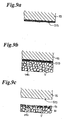
Fig.5 diagrammatically shows a phenomenon caused on the
outer shell material powders applied on the material contacting
surface of the die, a phenomenon caused on the outer shell
material powders applied on the material contacting surface of
the lower punch, and a phenomenon caused on the outer shell
material powders applied on the material contacting surface of
the upper punch when a molding material is compressed with the
die, the upper punch and the lower punch of which material
contacting surfaces are applied with the outer shell material
powders according to the present invention.
Fig.6 is an explanatory view showing one embodiment of the
compression molded product (viable bacteria containing
compression molded product) according to the present invention,
Fig.6a is its perspective view, and Fig.6b is its sectional view.
Fig.7 is an explanatory view showing an enlarged
construction of the outer shell formed on the compression molded
product body (viable bacteria containing compression molded
product body) shown in Fig.6, Fig.7a is its plane view, and Fig.7b
is its sectional view.
Fig.8 shows procedures explaining one embodiment of the
production method of the compression molded product (viable
bacteria containing compression molded product) of the present
invention.
Fig.9 diagrammatically shows a phenomenon caused on the
outer shell material powders applied on the material contacting
surface of the die, a phenomenon caused on the outer shell
material powders applied on the material contacting surface of
the lower punch, and a phenomenon caused on the outer shell
material powders applied on the material contacting surface of
the upper punch when a molding material is compressed with the
die, the upper punch and the lower punch of which material
contacting surfaces are applied with the outer shell material
powders according to the production method of viable bacteria
containing compression molded product of the present invention.
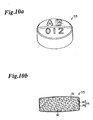
Fig.10 is an explanatory view showing one embodiment of the
compression molded product (microcapsule containing
compression molded product) according to the present invention,
Fig.10a is its perspective view, and Fig.10b is its sectional
view.
Fig.11 is an explanatory view showing an enlarged
construction of the outer shell formed on the body of the
compression molded product (microcapsule containing
compression molded product) shown in Fig.10, Fig.11a is its plan
view, and Fig.11b is its sectional view.
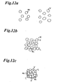
Fig.12 shows procedures explaining one embodiment of the
production method of the compression molded product
(microcapsule containing compression molded product) of the
present invention.
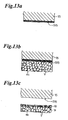
Fig.13 diagrammatically shows a phenomenon caused on the
outer shell material powders applied on the material contacting
surface of the die, a phenomenon caused on the outer shell
material powders applied on the material contacting surface of
the lower punch, and a phenomenon caused on the outer shell
material powders applied on the material contacting surface of
the upper punch when a molding material is compressed with the
die, the upper punch and the lower punch of which material
contacting surfaces are applied with the outer shell material
powders according to the production method of microcapsule
containing compression molded product of the present invention.
Fig.14 shows one embodiment of the outer shell material
powders spray means used for the compression molded product
manufacturing means of the present invention.
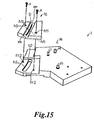
Fig.15 shows an exploded perspective view showing a concept
of one embodiment of the outer shell material powders spray means
used for the compression molded product manufacturing method
of the present invention.
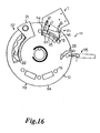
Fig.16 is a plane view showing where the outer shell material
powder spray means used for the compression molded product
manufacturing method of the present invention is installed.
Fig.17 is an enlarged plane view showing how the outer shell
material powder spray means is attached to a spray point of the
outer shell material powders of a rotary type tabletting machine
used for the compression molded product manufacturing method
of the present invention.
Fig.18 shows a diagrammatical section of the outer shell
material powder spray means along the line XVIII - XVIII in Fig.17
used for the compression molded product manufacturing method
of the present invention.
Fig.19 is a plane view diagrammatically showing one
embodiment of the outer shell material powders spray unit for
upper punch which is used for the outer shell material powder
spray means used for the compression molded product
manufacturing method of present invention.
Fig.20 is a plane view diagrammatically showing other
embodiment of the outer shell material powders spray unit for
upper punch which is used for the outer shell material powder
spray means used for the compression molded product
manufacturing method of the present invention.
Fig.21 is a plane view diagrammatically showing still other
embodiment of the outer shell material powders spray unit for
upper punch which is used for the outer shell material powder
spray means used for the compression molded product
manufacturing method of the present invention.
Fig.22 is a plane view diagrammatically showing still other
embodiment of the outer shell material powders spray unit for
upper punch which is used for the outer shell material powder
spray means used for the compression molded product
manufacturing method of the present invention.
Fig.23 is a plane view diagrammatically showing still other
embodiment of the outer shell material powders spray unit for
upper punch which is used for the outer shell material powder
spray means used for the compression molded product
manufacturing method of the present invention.
Fig.24 is an explanatory view diagrammatically showing the
principle of operation of the outer shell material powder spray
means used for the compression molded product manufacturing
method of the present invention.
Fig.25 is a time chart diagrammatically showing a spraying
method (operation and principle) of the shell material (powders)
on an inner circumference of a die, an upper face of a lower
punch and a lower face of an upper punch by the shell material
spray means used for the compression molded product
manufacturing method of the present invention.
Fig.26 shows an entire construction of an externally
lubricating type tabletting machine provided with the outer
shell material powder spray means used for the compression
molded product manufacturing method of the present invention.
Fig.27 shows a construction of a quantitative feeder which
is preferably used with the outer shell material powder spray
means according to the compression molded product manufacturing
method of the present invention.
Fig.28 is an explanatory view showing a powder storage
hopper which is preferably used with the outer shell material
powder spray means according to the compression molded product
manufacturing method of present invention, Fig.28a is a
partially cut-away perspective view of the hopper, and Fig.28b
is a plan view of the hopper.
Fig.29 is a plane view of one embodiment of an elastic
membrane used for the quantitative feeder of Fig.27.
Fig.30 is a plane view of another embodiment of an elastic
membrane used for the quantitative feeder of Fig.27.
Fig.31 is a perspective view diagrammatically showing
elastic membrane installation means used for the quantitative
feeder shown in Fig.27 and shows where the elastic membrane is
already attached.
Fig.32 is an exploded perspective view diagrammatically
showing the construction of the elastic membrane installation
means shown in Fig.27.
Fig.33 is a sectional view diagrammatically showing the
construction of the elastic membrane installation means in
Fig.27.
Fig.34 is a plane view showing the direction of an attachment
position of a pulsating vibration air supply port provided for
a dispersion chamber when the dispersion chamber of Fig.27 is
seen from the top, Fig.34a is an explanatory view showing a
direction of a preferable attachment position of the pulsating
vibration air supply port against the dispersion chamber, and
Fig.34b is an explanatory view showing a direction of a practical
attachable position of the pulsating vibration air supply port
against the dispersion chamber.
Fig.35 is a plane view showing the direction of an attachment
position of a pulsating vibration air supply port and a pulsating
vibration air discharge port provided for a dispersion chamber
when the dispersion chamber of Fig.27 is seen from the top,
Fig.35a is an explanatory view showing a direction of a
preferable attachment position of the pulsating vibration air
supply port and the pulsating vibration air discharge port
against the dispersion chamber, and Fig.35b is an explanatory
view showing a direction of a practical attachable position of
the pulsating vibration air supply port and the pulsating
vibration air discharge port against the dispersion chamber.
Fig.36 is a diagrammatical sectional view showing the
construction of pulsating vibration air generation means
suitably used with the outer shell material powder spray means
around pulsating vibration air conversion means according to
the production method of the compression molded product of the
present invention.
Fig.37 shows a diagrammatical enlarged construction around
the concentration measuring means of a shell material of Fig.26.
Fgi.38 is a flow chart diagrammatically showing an operation
program of an externally lubricating type tabletting machine
which is in advance stored in a memory of a processing unit of
the tabletting machine provided with the outer shell material
powder spray means according to the compression molded product
manufacturing means of the present invention.
Fig.39 is an explanatory view diagrammatically showing
operations of gas injection nozzle means and operations of a
material feed valve, both of which are provided with a powder
material storing hopper of a quantitative feeder of an
externally lubricating type tabletting machine providing the
outer shell material powder spray means according to the
compression molded product manufacturing means of the present
invention.
Fig.40 explains operations of an elastic member of a
quantitative feeder suitably used with outer shell material
powder spray means according to the compression molded product
manufacturing method of the present invention.
Fig.41 is a partially cut-away view showing another
construction of pulsating vibration air generation means
preferably used with outer shell material powder spray means
according to the compression molded product manufacturing
method of the present invention.
Fig.42 is an exploded perspective view showing other
construction of pulsating vibration air generation means
preferably used with the outer shell material powder spray means
according to the compression molded product manufacturing
method of the present invention.
Fig.43 is a partially cut-away diagrammatical perspective
view showing one embodiment of the prior viable bacteria
containing tablet.
Fig.44 is a partially cut-away diagrammatical perspective
view showing one embodiment of the prior microcapsule containing
tablet.
Fig.45 is a diagrammatical sectional view of the prior
microcapsule.
Fig.46 is an explanatory view showing how damages are
generated for viable bacteria contained in a molding material
to be compressed even at a low tabletting pressure according
to a prior method for manufacturing viable bacteria containing
tablet.
Fig.47 is an explanatory view showing how damages are
generated for microcapsules contained in a molding material to
be compressed even at a low tabletting pressure according to
a prior method for manufacturing microcapsule containing
tablet.
Best Mode for Carrying Out the Invention
Now, embodiments of the compression molded product of the
present invention will be more detailed referring to the
attached drawings.
(Embodiment 1)
Fig.1 is an explanatory view diagrammatically explaining
the compression molded product of the present invention, Fig.1a
is its perspective view and Fig.1b is its sectional view.
The compression molded product (tablet) ti1 has a
compression molded product body (tablet body) ta and an outer
shell tb formed on the surface of the body ta.
When the compression molded product (tablet) ti1 is a
medical tablet, an animal drug tablet, an agricultural tablet,
the compression molded product body (tablet body) ta is
comprised by compressing powder mixture of an active agent, an
excipient such as lactose, a supplement, an adjuvant and other
material if necessary.
The compression molded product body (tablet body) ta
preferably doesn't include a lubricant.
It is because lubricants aren't required to be contained
in the molding material and they are required to exist between
the molding material to be compressed and the material
contacting surfaces of the dies, the lower punches and the upper
punches in order to prevent the molding material from adhering
to those surfaces. Further, if lubricant powders are added,
the dissolving time and disintegration time of the compression
molded product (tablet) ti1 are delayed because of the water
repellency of the lubricant so that absorption into the human
body is deteriorated or appearance of effect is delayed.
If the compression molded product (tablet) ti1 is a chewable
tablet and is chewed in the mouth to be dissolved with saliva,
a person feels unpleasant taste (bitter taste) because of the
repellency of the lubricant in case that lubricant powders are
included in the compression molded product body (tablet body)
ta.
In addition, when the compression molded product (tablet)
ti1 is a food tablet, the compression molded product body (tablet
body) ta is comprised by compressing powders mixed with
components which are considered to be good for health like viable
bacteria such as acidophilus (freeze dry pulverized product),
chlorella (freeze dry pulverized product), beta-carotene, and
several kinds of vitamin; nutritional supplements; excipients
such as a saccharide like mannitol and sugar alcohol; if
necessary supplements; and adjuvants.
However, the compression molded product body (tablet body)
ta is preferable not to include sucrose esters of fatty acid
powders, glycerine fatty acid ester powders, hydrogenate oil
and fat powders.
Such a compression molded product (tablet) ti1 for food may
be swallowed together with water or may be a chewable tablet
which is chewed to be dissolved with saliva in the mouth without
requiring water. If sucrose esters of fatty acid powders,
glycerine fatty acid ester powders, hydrogenate oil and fat
powders are added in the compression molded product body (tablet
body) ta, the dissolving time and disintegration time of the
compression molded product (tablet) ti1 are delayed because of
their repellency, thereby deteriorating absorption of the
component which is considered to be good for health and/or the
active ingredients of nutritional supplement into the human body
and delaying the appearance of effects.
The outer shell tb is comprised of a material having higher
hardness than the compression molded product body (tablet body)
ta. Therefore, the outer shell tb brings out a wear resistance
so that the compression molded product (tablet) til is prevented
from chipping the surface thereof during storage or
transportation.
Fig.2 is an explanatory view showing an enlarged
construction of the outer shell tb formed on the body (tablet
body) ta of the compression molded product (tablet) ti1 shown
in Fig.1, Fig.2a is its plan view, and Fig.2b is its sectional
view.
The outer shell tb includes parts ptc··· where some outer
shell material powders are thermally melted to be solidified
each other.
As far as the outer shell tb includes the parts ptc···, it
may include parts where thermally melted outer shell material
powders are solidified to non-thermally melted powders.
Further, for example, the outer shell tb may include the
particles of the powders comprising the compression molded
product body (tablet body) ta or parts where the thermally melted
outer shell material powders are solidified to the particles
of the powders comprising the compression molded product body.
The particle diameter of the outer shell material powders
isn't specifically limited, but it may be preferably a little
larger than that of the lubricant powders added in the molding
material. Namely, the particle diameter of the outer shell
material powders is preferably within the range of 5µm to 50
µm, more preferably from 10µm to 20µm, furthermore preferably
from 10µm to 15µm.
It is because if outer shell material powders having too
little particle diameter are used, the outer shell tb is
constructed to be too dense after a part of the powders is
thermally melted to form the outer shell tb, therefore the
physicalities of the compression molded product body (tablet
body) ta and that of the outer shell tb are considerably different
and the characteristic as uncoated tablets is damaged.
Further, if outer shell material powders having too large
particle diameter are used, the surface of the compression
molded product ti1 becomes coarse to make the wear resistance
of the outer shell tb being damaged.
A melting point of the material powders of the outer shell
tb is preferably greater than or equal to 30°C and less than or
equal to 80°C, more preferably, greater than or equal to 40°C
and less than or equal to 78°C.
It is because the heat generated in case of compressing the
material by means of the dies, the lower punches and the upper
punches varies depending on the tabletting pressure of
compression, the amount of material to be molded, and the
component and composition of the molding material. However,
the dies, the lower punches and the upper punches generate heat
from 30°C to 80°C in case of tabletting.
Accordingly, if the outer shell material powders having a
melting point (m.p.) in the above-mentioned temperature range
are used , the outer shell tb including parts ptc··· where some
outer shell material powders are thermally melted to be
solidified each other on the surface of the compression molded
product body (tablet body) ta is formed.
Next, a preferable embodiment of the material powders of
the outer shell tb will be explained.
The material powders of the outer shell tb are preferably
fatty acid ester, fatty acid metallic salt and fatty acid ester.
There are sucrose esters of fatty acid and glycerine fatty
acid ester as fatty acid ester.
There are a saccharide such as glucose, sucrose, a sugar
alcohol such as sorbitol and mannitol as a sugar of sucrose esters
of fatty acid.
Further there is saturated fatty acid of which carbon number
is equal to or more than 12 and equal to or less than 22 such
as dodecanoic acid, tridecanoic acid, tetradecanoic acid,
pentadecanic acid, hexadecanoic acid, heptadecanic acid,
octadecanoic acid (stearic acid), nonadecylic acid, icosanic
acid, henicosanic acid, docosanic acid (there melting points
(m.p) are within the range of 44.2°C to 79.9°C) as fatty acid
component of fatty acid, fatty acid metal salt or sucrose esters
of fatty acid.
Metal salt component of fatty acid metal salt is for example
aluminum (Al), sodium (Na), pottasium (K), calcium (Ca),
magnesium (Mg).
Specifically, there is stearic acid metal salt (Al, Na, K,
Ca, Mg) as fatty acid metal salt.
More specifically, powders of sucrose ester of fatty acid,
glycerine fatty acid ester powders, hydrogenate oil and fat
powders or stearic acid powders are used as preferable
embodiments of the material powders of the outer shell tb.
Sucrose esters of fatty acid has the melting point (m.p.)
within the range of about 52°C to 62°C, is superior in safety,
is easily obtainable and achieves excellent abrasion resistance
function as an outer shell, thereby being suitable for the shell
material.
Further glycerine fatty acid ester has the melting point
(m.p.) within the range of about 62°C to 68°C, is superior in
safety, is easily obtainable and achieves excellent abrasion
resistance function as an outer shell, thereby being suitable
for the shell material.
Furthermore, hydrogenate oil and fat has the melting point
(m.p.) within the range of about 40°C to 48°C, is superior in
safety, is easily obtainable and achieves excellent abrasion
resistance function as an outer shell, thereby being suitable
for the shell material.
Still further, stearic acid has the melting point (m.p.)
within the range of about 56°C to 72°C, is superior in safety,
is easily obtainable and achieves excellent abrasion resistance
function as an outer shell, thereby being suitable for the shell
material.
Because sucrose esters of fatty acid, glycerine fatty acid
ester, hydrogenate oil and fat and stearic acid have a function
of a lubricant (molding lubricant), when a molding material is
compressed using dies, upper punches and lower punches on which
material contacting surfaces are applied with them, the molding
material doesn't adhere on the surfaces because they functions
as a lubricant. As a result, the frequency of the tabletting
problems such as sticking, laminating and capping is reduced
when the compression molded product is produced, thereby
achieving high productivity (industrially profitable).
The compression molded product (tablet) til is formed with
the outer shell tb including parts ptc··· where some outer shell
material powders are thermally melted to be solidified each
other, thereby preventing chipping during storage or
transportation.
More specifically, the compression molded product (tablet)
ti1 is covered with the outer shell tb including the parts ptc···
where some outer shell material powders are thermally melted
to be solidified each other, not the shell formed only by
compressing the outer shell material powders to be engaged and
bonded. Therefore, the outer shell tb of the compression molded
product body (tablet) ti1 of the present invention has a higher
mechanical strength and hardly causes chipping during storage
or transportation comparing with the outer shell formed by
compression.
On the other hand, the outer shell tb formed on the surface
of the compression molded product (tablet) ti1 includes the
parts ptc··· where some outer shell material powders are
thermally melted to be solidified each other. Comparing with
the outer shell formed by spraying a coating liquid on the naked
tablet's surface to be dried, the compression molded product
ti1 is fragile and easily disintegrated when being chewed in
the mouth. Therefore, there arises no uncomfortable feeling
caused by the difference of the physical properties of the
compression molded product body (tablet body) ta and the outer
shell tb when the product t11 is chewed in the mouth, thereby
suitable for chewable tablets.
Furthermore, only the outer shell tb is formed on the
compression molded product (tablet) ti1 so that such product
ti1 has rapid dissolving time and disintegration time so as to
be immediately dissolved in a desired part if a lubricant isn't
included in the compression molded product body (tablet body)
ta.
Therefore, such a compression molded product (tablet) ti1
is rapidly absorbed in the human body and has a rapid action
if a lubricant isn't contained in the compression molded product
body (tablet body) ta.
Still further, if such a compression molded product (tablet)
ti1 is a chewable tablet without including lubricant in the
compression molded product body (tablet body) ta, the chewable
tablet doesn't give an unpleasant taste (bitter taste) to a
person chewing the tablet in the mouth because a lubricant isn't
included in the compression molded product body (tablet body)
ta. Therefore, the product ti1 has a superior taste as a
chewable tablet when a lubricant isn't included in the
compression molded product body (tablet body) ta.
The outer shell tb formed on the surface of the compression
molded product body (tablet body) ta doesn't melt under 30°C
so that it is solid at a room temperature (1°C~30°C) and a cool
place (less than 15°C), thereby preventing chipping of the
surface of the compression molded product (tablet) ti1 in case
of storage or transportation.
When such a compression molded product (tablet) ti1 having
the outer shell material powder with a relatively low melting
point within the above-mentioned range is taken in the mouth,
the outer shell tb quickly melts therein like an uncoated tablet
so that it can be used as a chewable tablet.
Next, a production method of the compression molded product
(tablet) ti1 will be explained.
Fig.3 shows procedures explaining one embodiment of the
production method of the compression molded product (tablet)
ti1.
A tabletting machine is prepared for producing the
compression molded product (tablet) ti1. Fig.3a is a sectional
view diagrammatically showing a die 13, corresponding lower
punch 14 and corresponding upper punch 15. The member indicated
by the numeral 12 in Fig.3a is a part of a turntable of the
tabletting machine. The die 13 is formed on the turntable 12.
Then, the lower punch 14 is inserted in a predetermined
position in the die 13.
A molding material contacting surface S13 of the die 13 is
defined by the position of a molding material contacting surface
S14 (upper face) of the lower punch 14 inserted in the die 13.
Namely the surface S13 is a part above the surface S14 of
the lower punch 14 in the inner circumference of the die 13.
The material powders for the outer shell tb are uniformly
sprayed with a predetermined thickness on the molding material
contacting surface S13 of the die 13, the surface S14 (upper
face) of the upper punch 14 and the surface S15 (lower face)
of the upper punch 15.
The outer shell material powders which have a function of
a lubricant (molding lubricant) and has a melting point (m.p.)
of greater than or equal to 30°C and less than or equal to 80°C,
more preferably, greater than or equal to 40°C and less than or
equal to 78°C is preferably used.
Specifically, powders of sucrose esters of fatty acid,
glycerine fatty acid ester powders, hydrogenate oil and fat
powders or stearic acid powders are used.
The particle diameter of the outer shell material powders
isn't specifically limited, but it may be preferably a little
larger than that of the lubricant powders added in the molding
material. Namely, the particle diameter of the outer shell
material powders is preferably within the range of 5µm to 50
µm, more preferably from 10µm to 20µm, furthermore preferably
from 10µm to 15µm.
It is because if outer shell material powders having too
little particle diameter are used, the outer shell tb is
constructed to be too dense after a part of the powders is
thermally melted to form the outer shell tb, therefore the
physicalities of the compression mold product body (tablet body)
ta and that of the outer shell tb are considerably different
and the characteristic as naked tablets is damaged.
Further, if outer shell material powders having too large
particle diameter are used, the surface of the compression
molded product (tablet) ti1 becomes coarse to make the wear
resistance of the outer shell tb being damaged.
There are several kinds of methods for uniformly spraying
the outer shell material powders comprising the outer shell tb
at a predetermined thickness on the material contacting surfaces
S13 of the die 13, the surface S14 (upper face) of the lower
punch 14 and the surface S15 (lower face) of the upper punch
15. One preferable method is that the outer shell material
powders mixed and dispersed with a positive pulsating vibration
air and is sprayed together with the positive pulsating
vibration air from nozzle means (not shown) to the surfaces S13,
S14 and S15.
The "pulsating vibration air" means an air wave in which
high pressure parts (low air current speed) and low pressure
parts (high air current speed) are alternately appeared in an
air flow in a predetermined cycle.
The term "positive" means the air pressure in the instrument
for executing the compression molded product manufacturing
method is higher than the air pressure outside thereof.
Fig.4a and Fig.4b are explanatory views showing an example
of the positive pulsating vibration air used for spraying the
outer shell material powders on the material contacting surface
S13 of the die 13, the surface (upper face) S14 of the lower
punch 14 and the surface (lower face) S15 of the upper punch
15.
Such a positive pulsating vibration air may be a pulsating
vibration air of which amplitude peak is higher than the
atmospheric pressure and of which amplitude valley is almost
equal to the atmospheric pressure as shown in Fig.4a, and a
pulsating vibration air of which amplitude peak and amplitude
valley are higher than the atmospheric pressure as shown in
Fig.4b.
The positive pulsating vibration air used for this
production method is set at a frequency, wavelength, wave shape
and amplitude suitable for mixing and dispersing the outer shell
material powders with the air.
In this production method, a positive pulsating vibration
air with a suitable frequency, wavelength, wave shape and
amplitude is used depending on the physical properties
(component, composition, average particle diameter and particle
size distribution) of the using outer shell material powders.
Accordingly, the outer shell material powders are easily
mixed with such a pulsating vibration air and hardly separated
to be accumulated like the powders dispersed with a steady flow
air.
Hence, approximately a fixed amount of outer shell material
powders can be kept being mixed and dispersed with the positive
pulsating vibration air for a long time comparing with the
powders mixed with a steady flow air.
Further, because high pressure parts (low air current speed)
and low pressure parts (high air current speed) are alternately
appeared in the positive pulsating vibration flow, even if extra
outer shell material powders are adhered and accumulated on the
material contacting surface S14 (upper face) of the lower punch
14 on which the powders are apt to be accumulated by gravity,
high pressure parts and low pressure parts are alternately
sprayed, then the extra powders are blown out of the lower punch's
material contacting surface S14. Consequently, a minimum
amount of outer shell material powders is uniformly applied on
the material contacting surface S14 (upper face) of the lower
punch 14 on which extra powders are apt to be deposited.
The outer shell material powders which have been sprayed
on the lower punch's material contacting surface S14 (upper
face) and blown out thereof adhere on the material contacting
surface of the die S13 (the inner circumference wall). Even
if extra powders are adhered and accumulated on the die's
material contacting surface S13, high pressure parts (low air
current speed) and low pressure parts (high air current speed)
are alternately sprayed on the surface S13, as a result, extra
powders are sprayed therefrom. Finally a minimum amount of
outer shell material powders is uniformly applied on the
material contacting surface S13 (inner circumferential wall)
of the die 13.
Although the outer shell material powders have difficulty
in adhering and accumulating on the material contacting surface
S15 (lower face) of the upper punch 15 by gravity, they are
sprayed together with a positive pulsating vibration air so that
a minimum amount of powders can be uniformly applied on the upper
punch's material contacting surface S15.
As shown in Fig.3c, a molding material is charged in the
space formed in the die 13 wherein the space is comprised of
the material contacting surface S13 (inner circumference) of
the die and the material contacting surface S14 (upper face)
of the lower punch 14 which is inserted in a predetermined place
in the die 13, and the surfaces S13 and S14 are applied with
the outer shell material powders.
If the compression molded product (tablet) ti1 is medical
tablets, animal drug tablets and agricultural chemical tablets,
several materials such as active agent powders, excipient
powders such as lactose, if necessary supplement powders and
adjuvant powders may be included in the molding material.
However, lubricants aren't preferably included in the
molding material.
It is because, as mentioned above, the outer shell material
powders have a function of a lubricant (molding lubricant), and
the material contacting surface S13 (inner circumference) of
the die 13, the material contacting surface S14 (upper face)
of the lower punch 14 and the material contacting surface S15
(lower face) of the upper punch 15 are applied with such powders.
Therefore, the molding material doesn't adhere on the surfaces
S13, S14 and S15 during compression even if a lubricant isn't
added therein so that tabletting problems such as sticking,
laminating and capping aren't caused for the produced
compression molded product (tablet) ti1 and grinding is hardly
caused for the die 13, the lower punch 14 and the upper punch
15.
Further, if lubricant powders are added in the molding
material, the dissolving time and disintegration time of the
compression molded product (tablet) ti1 are delayed because of
their repellency, thereby deteriorating absorption of the
active ingredients into the human body and delaying the
appearance of effects.
Still further, if the compression molded product (tablet)
ti1 is a chewable tablet and is chewed in the mouth to be dissolved
with saliva, a person feels unpleasant taste (bitter taste)
because of the repellency of a lubricant in case that lubricant
powders are included in the compression molded product body
(tablet body) ta.
In addition, when the compression molded product (tablet)
ti1 is a food tablet, powders mixed with components which are
considered to be good for health like viable bacteria such as
acidophilus (freeze dry pulverized product), chlorella (freeze
dry pulverized product), beta-carotene, and several kinds of
vitamin; and/or nutritional supplements; excipients such as a
saccharide like mannitol and sugar alcohol; if necessary
supplements; and adjuvants.
However, the molding material is preferable not to include
powders of sucrose ester of fatty acid, glycerine fatty acid
ester powders, hydrogenate oil and fat. Further, it is better
not to include a lubricant.
It is because such a compression molded product (tablet)
ti1 for food products may be swallowed together with water or
may be a chewable tablet which is chewed to be dissolved with
saliva in the mouth without requiring water. If sucrose esters
of fatty acid powders, glycerine fatty acid ester powders,
hydrogenate oil and fat are added in the compression molded
product body (tablet body) ta, the dissolving time and
disintegration time of the compression molded product (tablet)
ti1 are delayed because of their repellency, thereby
deteriorating absorption of the component which is considered
to be good for health and the active ingredients of nutritional
supplement into the human body and delaying the appearance of
effects.
As shown in Fig.3d, a molding material charged in the space
formed by the die 13 and the lower punch 14 is compressed by
means of the die 13 having the material contacting surface S13
(inner circumference) and the lower punch 14 having the material
contacting surface S14 (upper face) and the upper punch 15 having
the material contacting surface S15 (lower face), on those
surfaces being applied with the outer shell material powders.
Fig.5 diagrammatically shows a phenomenon caused on the
outer shell material powders applied on the material contacting
surface S13 (inner circumference) of the die 13, a phenomenon
caused on the outer shell material powders applied on the
material contacting surface S14 (upper face) of the lower punch
14, and a phenomenon caused on the outer shell material powders
applied on the material contacting surface S15 (upper face) of
the upper punch 15 when a molding material is compressed with
the die, the upper punch and the lower punch of which material
contacting surfaces are applied with the outer shell material
powders.
In the figure, the phenomenon caused on each material
contacting surface of the die 13, the lower punch 14 and the
upper punch 15 is almost the same, therefore, only the phenomenon
caused on the outer shell material powders on the material
contacting surface (lower face) S15 of the upper punch 15 is
shown and each phenomenon caused on the powders on the material
contacting surfaces S13 and S14 is omitted to be shown.
The outer shell material powders applied on the material
contacting surface (lower face) S15 of the upper punch 15 adhere
thereon while being absorbed each other as shown in Fig.5a.
Compression of a molding material is started by means of
the die 13 having the material contacting surface S13 (inner
circumference), the lower punch 14 having the material
contacting surface S14 (upper face) and the upper punch 15 having
the material contacting surface S15 (lower face), on those
surfaces being applied with the outer shell material powders.
Then the material contacting surface S15 is pushed into the
surface of the molding material to be compressed so that the
material contacting surface (lower face) S15 of the upper punch
15 gets in touch with the molding material surface (see Fig.5b).
Next, when the molding material is molded by means of the
die 13 having the material contacting surface S13 (inner
circumference), the lower punch 14 having the material
contacting surface S14 (upper face) and the upper punch 15 having
the material contacting surface S15 (lower face), on those
surfaces being applied with the outer shell material powders,
the molding material generates heat by being compressed with
the die, the lower punch 14 and the upper punch 15.
Further the outer shell material powders applied on the
material contacting surface S13 of the die 13, the surface S14
(upper face) of the lower punch 14 and the surface S15 (lower
face) of the upper punch 15 are compressed to generate heat.
Then some of the outer shell material powders applied on
the material contacting surface (inner circumference) S13 of
the die 13 are thermally melted, the thermally melted powders
are solidified each other, the thermally melted powders and
non-thermally melted powders are solidified and thermally
melted powders are solidified to the powder particles of the
molding material, thereby the outer shell tb is formed on the
surface of the compression molded product body (tablet body)
ta.
In the same manner some of the outer shell material powders
applied on the material contacting surface (upper face) S14 of
the lower punch 14 are thermally melted, the thermally melted
powders are solidified each other, the thermally melted powders
and non-thermally melted powders are solidified and thermally
melted powders are solidified to the powder particles of the
molding material, thereby the outer shell tb is formed on the
surface of the compression molded product body (tablet body)
ta.
Also, some of the outer shell material powders applied on
the material contacting surface (lower face) S15 of the upper
punch 15 are thermally melted, the thermally melted powders are
solidified each other, the thermally melted powders and
non-thermally melted powders are solidified and thermally
melted powders are solidified to the powder particles of the
molding material, thereby the outer shell tb is formed on the
surface of the compression molded product body (tablet body)
ta (see Fig.5c).
As mentioned above, the compression molded product (tablet)
ti1 having the outer shell tb including a part where some shell
material are thermally melted to be solidified each other on
the compression molded product body (tablet body) ta can be
produced.
Thus produced compression molded product (tablet) ti1 is
taken out of the die 13 when the lower punch 14 is moved upwardly
in the die 13 (see Fig.3e).
According to this method for producing a compression molded
product, the molding material is compressed by means of the die
13, the lower punch 14 and the upper punch 15 of which material
contacting surfaces S13 (inner circumference), S14 (upper face)
and S15 (lower face) are sprayed with the outer shell material
powders and compression molded product bodies (tablet bodies)
tb are produced. At the same time, at least a part of the outer
shell material powders applied on the material contacting
surface S13 of the die 13, a part of the outer shell material
powders applied on the material contacting surface S14 of the
lower punch 14, and/or a part of the outer shell material powders
applied on the material contacting surface S15 of the upper punch
15 are thermally melted, then the outer shell tb is formed on
the surface of the compression molded product body (tablet body)
ta by transposing the thermally melted material on the material
contacting surfaces S13, S14 and S15 of the die 13, the lower
punch 14 and the upper punch 15.
Thus a part of the outer shell material powders applied on
the material contacting surfaces S13, S14 and S15 is thermally
melted by the heat generated in case of compression, the
thermally melted outer shell material powders are solidified
each other, the thermally melted outer shell material powders
and non-thermally melted ones are solidified each other and/or
the thermally melted outer shell material powders are solidified
to the powder particles of the molding material.
Then the outer shell material powders thermally melted to
be solidified by the heat generated by compression are
transferred on the surface of the compression molded product
body (tablet body) ta from the material contacting surfaces S13,
S14 and S15 of the die 13, the lower punch 14 and the upper punch
15. Accordingly the compression molded product ti1 wherein the
outer shell tb including parts ptc··· where some outer shell
material powders are thermally melted to be solidified each
other at a part thereof is formed on the surface of the
compression molded product body (tablet body) ta can be
produced.
According to such a production method of the compression
molded product, when the molding material is compressed by the
die 13, the lower punch 14 and the upper punch 15 to produce
a compression molded product body (tablet body) ta, the outer
shell tb is simultaneously formed on the surface of the
compression molded product body (tablet body) ta. Therefore,
a coating procedure isn't required wherein the outer shell tb
is formed on the surface of the uncoated tablets obtained by
compression by means of coating means. Accordingly the
production line doesn't need to be provided with two lines, a
compression molding procedure and a coating procedure so that
a compression molded product (tablet) ti1 having the outer shell
tb can be manufactured only by a compression molding procedure.
Hence, according to such a production method of the
compression molded product which can manufacture the
compression molded product ti1 with the outer shell tb only by
a compression molding procedure, the production procedure is
extremely simplified, thereby enabling its manufacturer's cost
to be reduced.
In addition, the outer shell tb formed on the surface of
the compression molded product ti1 by the compression molded
product manufacturing method of the present invention includes
the parts ptc··· where a part of the outer shell material powders
is thermally melted and the thermally melted powders are
solidified each other. The compression molded product body ta
is covered with the outer shell tb including the parts ptc···
where a part of the outer shell material powders is thermally
melted to be solidified each other, not the outer shell formed
only by compressing the outer shell material powders to be
engaged and bonded. Therefore, the outer shell tb of the
compression molded product t of the present invention has a
higher mechanical strength and hardly causes chipping during
storage or transportation comparing with the outer shell formed
only by compression.
The outer shell tb formed on the surface of the compression
molded product t includes the parts ptc··· where some of the outer
shell material powders are thermally melted to be solidified
each other. Comparing with the outer shell formed by spraying
a coating liquid on the naked tablet's surface to be dried, the
compression molded product ti1 is fragile and easily
disintegrated when being chewed in the mouth. Therefore, there
arises no uncomfortable feeling caused by the difference of the
physical properties of the compression molded product body
(tablet body) ta and the outer shell tb when the product body
is chewed in the mouth, thereby the product (tablet) ti1 is
suitable for chewable tablets.
In this method, the outer shell material powders with a
melting point from 30°C to 80°C are used so that the outer shell
tb including the parts ptc··· where some of the powders are
thermally melted to be solidified each other is formed on the
surface of the compression molded product body (tablet body)
ta.
The outer shell tb formed on the compression molded product
surface according to this production method doesn't melt under
30°C, therefore, it is solid under room temperature (1°C - 30°C)
and in a cool place (under 15°C), thereby preventing chipping
while storage or transportation as far as the products are stored
and transported under room temperature or in cool places.
Further, when the outer shell material powders with a
relatively low melting point within the above-mentioned range
are used and its compression molded product is taken in the mouth,
the outer shell tb is easily dissolved therein and has the same
characteristic as uncoated tablets, thereby the product
(tablet) ti1 doesn't give unpleasant feeling as a chewable
tablet.
This method uses the outer shell material powders which are
superior in safety, are easily obtainable, bring out a wear
resistance and have a function as a lubricant (molding
lubricant), the compression molded product (tablet) ti1 which
is superior in safety and hardly causes chipping on the surface
thereof during storage or transportation can be produced at a
high productivity in manufacturing.
(Embodiment 2)
Fig.6 is an explanatory view showing one embodiment of a
viable bacteria containing compression molded product according
to the present invention, Fig.6a is its perspective view, and
Fig.6b is its sectional view.
The compression molded product (viable bacteria containing
compression molded product (tablet)) ti2 has a compression
molded product body (tablet body) ta including viable bacteria
vmc··· and an outer shell tb formed on the surface of the
compression molded product body ta.
When the compression molded product (viable bacteria
containing compression molded product (tablet)) ti2 is a medical
tablet, an animal drug tablet, and an agricultural tablet, the
compression molded product body (tablet body) ta other than the
viable bacteria vmc··· (namely matrix (connection part)) is
comprised by compressing powders mixed with an excipient such
as lactose, a supplement, an adjuvant and other materials if
necessary.
According to the compression molded product (viable
bacteria containing compression molded product(tablet)) ti2,
the pharmaceutical powders other than the viable bacteria vmc···
of the compression molded product body (tablet body) ta is
comprised of a material having a melting point higher than the
heat generated at a time of compressing the molding material
including viable bacteria vmc···.
More specifically, if the compression molded product
(viable bacteria containing compression molded product
(tablet)) ti2 is medical tablets, a lubricant (stearic acid,
stearic acid metal salt (Al, Mg, K, Ca, Na)) which is usually
added in a molding material isn't included in the pharmaceutical
powders.
Further, if the compression molded product (viable bacteria
containing compression molded product (tablet)) ti2 is food
tablets, a lubricant (sucrose esters of fatty acid) which is
usually added in a molding material isn't included in the
pharmaceutical powders.
The outer shell tb is comprised of a material having a higher
hardness than the compression molded product body (tablet body)
ta. Therefore, the outer shell tb brings out a wear resistance
so that the compression molded product (tablet) ti2 is prevented
from chipping the surface thereof during storage or
transportation.
Fig.7 is an explanatory view showing an enlarged
construction of the outer shell tb formed on the surface of the
compression molded product (viable bacteria containing
compression molded product), Fig.7a is its plan view, and Fig.7b
is its sectional view.
The outer shell tb includes parts pt··· where some of the
outer shell material powders are thermally melted to be
solidified each other as shown in Fig.7a and Fig.7b.
As far as the outer shell tb includes the parts pt···, it
may include parts where thermally melted outer shell material
powders are solidified to non-thermally melted powders.
Further, for example, the outer shell tb may include the
particles of the powders comprising the compression molded
product body (tablet body) ta or parts where the thermally melted
outer shell material powders are solidified to the particles
of the powders comprising the compression molded product body
(tablet body) ta.
The particle diameter of the outer shell material powders
isn't specifically limited, but it may be preferably a little
larger than that of the lubricant powders added in the molding
material. Namely, the particle diameter of the outer shell
material powders is preferably within the range of 5µm to 50
µm, more preferably from 10µm to 20µm, furthermore preferably
from 10µm to 15µm.
It is because if outer shell material powders having too
little particle diameter are used, the outer shell tb is
constructed to be too dense after a part of the powders is
thermally melted to form the outer shell tb, therefore the
physicalities of the compression molded product body (tablet
body) ta and that of the outer shell tb are considerably different
and the characteristic as uncoated tablets is damaged.
Further, if outer shell material powders having too large
particle diameter are used, the surface of the compression
molded product t becomes coarse to make the wear resistance of
the outer shell tb being damaged.
A melting point of the material powders of the outer shell
tb is preferably greater than or equal to 30°C and less than or
equal to 80°C, more preferably, greater than or equal to 40°C
and less than or equal to 78°C.
It is because the heat generated in case of compressing the
material by means of a die 13, a lower punch 14 and an upper
punch 15 varies depending on the tabletting pressure of
compression, the amount of molding material including viable
bacteria vmc··· to be molded with the die 13, the lower punch
14 and the upper punch 15, and the component and composition
of the molding material including viable bacteria vmc···.
However, the die 13, the lower punch 14 and the upper punch 15
generate heat from 30°C to 80°C in case of tabletting.
Accordingly, if the outer shell material powders having a
melting point (m.p.) in the above-mentioned temperature range
are used, the outer shell tb including parts pt··· where some
outer shell material powders are thermally melted to be
solidified each other on the surface of the compression molded
product body (tablet body) ta including viable bacteria vmc···
is formed.
Preferable embodiments of the material powders of the outer
shell tb are, for example, powders of sucrose esters of fatty
acid, glycerine fatty acid ester powders, hydrogenate oil and
fat powders or stearic acid powders are used.
Sucrose esters of fatty acid has the melting point (m.p.)
within the range of about 52°C to 62°C, is superior in safety,
is easily obtainable and achieves excellent abrasion resistance
function as an outer shell, thereby being suitable for the shell
material.
Further glycerine fatty acid ester has the melting point
(m.p.) within the range of about 62°C to 68°C, is superior in
safety, is easily obtainable and achieves excellent abrasion
resistance function as an outer shell, thereby being suitable
for the shell material.
Furthermore, hydrogenate oil and fat has the melting point
(m.p.) within the range of about 40°C to 48°C, is superior in
safety, is easily obtainable and achieves excellent abrasion
resistance function as an outer shell, thereby being suitable
for the shell material.
Still further, stearic acid has the melting point (m.p.)
within the range of about 56°C to 72°C, is superior in safety,
is easily obtainable and achieves excellent abrasion resistance
function as an outer shell, thereby being suitable for the shell
material.
Because sucrose esters of fatty acid, glycerine fatty acid
ester, hydrogenate oil and fat and stearic acid have a function
of a lubricant (molding lubricant), when a molding material is
compressed using dies, upper punches and lower punches on which
material contacting surfaces are applied with them, the molding
material doesn't adhere on the surfaces because they functions
as a lubricant. As a result, the frequency of the tabletting
problems such as sticking, laminating and capping is reduced
when the compression molded product is produced, thereby
achieving high productivity (industrially profitable).
According to such a compression molded product (viable
bacteria containing compression molded product (tablet)) ti2,
the viable bacteria vmc··· contained in the product ti2 aren't
damaged and their survival rate is high, thereby an objective
function of the compression molded product ti2 is achieved.
The compression molded product (viable bacteria containing
compression molded product (tablet)) ti2 is formed with the
outer shell tb including parts pt··· where some outer shell
material powders are thermally melted to be solidified each
other, thereby preventing chipping during storage or
transportation.
More specifically, the compression molded product (viable
bacteria containing compression molded product (tablet)) ti2
is covered with the outer shell tb including the parts pt···
where some outer shell material powders are thermally melted
to be solidified each other, not the outer shell formed only
by compressing the outer shell material powders to be engaged
and bonded. Therefore, the outer shell tb of the compression
molded product ti2 of the present invention has a higher
mechanical strength and hardly causes chipping during storage
or transportation comparing with the outer shell formed by
compression.
On the other hand, the outer shell tb formed on the surface
of the compression molded product (viable bacteria containing
compression molded product (tablet)) ti2 includes the parts
where some of the outer shell material powders are thermally
melted to be solidified each other. Comparing with the outer
shell formed by spraying a coating liquid on the naked tablet's
surface to be dried, the compression molded product ti2 is
fragile and easily disintegrated when being chewed in the mouth.
Therefore, there arises no uncomfortable feeling caused by the
difference of the physical properties of the compression molded
product body (tablet body) ta and the outer shell tb when the
product ti2 is chewed in the mouth, thereby suitable for chewable
tablets.
Furthermore, only the outer shell tb is formed on the
compression molded product (viable bacteria containing
compression molded product (tablet)) ti2 and a lubricant isn't
included so that such product ti2 has rapid dissolving time and
disintegration time and can be immediately dissolved in a
desired part, thereby the viable bacteria vmc··· contained in
the tablet are released.
Still further, if such a viable bacteria containing
compression molding product ti2 which doesn't contain a
lubricant in the compression molded product body (tablet body)
'ta is a chewable tablet, the chewable tablet doesn't give an
unpleasant taste (bitter taste) to a person chewing the tablet
in the mouth because a lubricant isn't included in the
compression molded product body (tablet body) ta. Therefore,
the product ti2 has superior taste as a chewable tablet when
a lubricant isn't included in the compression molded product
body (tablet body) ta.
The outer shell tb formed on the surface of the compression
molded product body (tablet body) ta doesn't melt under 30°C
so that it is solid at a room temperature (1°C~30°C) and in a
cool place (less than 15°C), thereby preventing chipping of the
surface of the compression molded product (viable bacteria
containing compression molded product (tablet)) ti2 in case of
storage or transportation.
When such a compression molded product ti2 having the outer
shell material powder with a relatively low melting point within
the above-mentioned range is taken in the mouth, the outer shell
tb quickly melts therein like an uncoated tablet so that it can
be used as a chewable tablet.
Next, a production method of the compression molded product
(viable bacteria containing compression molded product
(tablet)) ti2 will be explained.
The compression molded product (viable bacteria containing
compression molded product (tablet)) ti2 is produced like the
compression molded product manufacturing method shown in Fig.3.
Fig.8 shows procedures explaining the production method of
the compression molded product (viable bacteria containing
compression molded product) ti2 of the present invention.
Viable bacteria vmc··· and excipients V··· are prepared as
shown in Fig.8a.
In this embodiment, viable bacteria vmc··· and excipients
V··· are prepared, however, an adjuvant such as a supplement may
be added.
When the pharmaceutical powders include excipients V··· and
an adjuvant such as a supplement, they are approximately
comprised of a material having a higher melting point than the
heat generated at a time of compression molding.
Then the viable bacteria vmc··· and excipients V···
(pharmaceutical powders when an adjuvant such as a supplement
is added other than the excipients) are mixed to prepare a molding
material M including the viable bacteria vmc···.
For manufacturing the compression molded product (viable
bacteria containing compression molded product (tablet)) ti2,
a tabletting machine is prepared.
A lower punch 14 is inserted into a predetermined position
in a die 13 as shown in Fig.3a.
A molding material contacting surface S13 of the die 13 is
defined by the position of a molding material contacting surface
S14 (upper face) of the lower punch 14 inserted in the die 13.
Namely the surface S13 is a part above the surface S14 of
the lower punch 14 in the inner circumference of the die 13.
The material powders for the outer shell tb are uniformly
sprayed at a predetermined thickness on the molding material
contacting surface S13 of the die 13, the surface S14 (upper
face) of the upper punch 14 and the surface S15 (lower face)
of the upper punch 15.
The outer shell material powders which have a function of
a lubricant (molding lubricant) and has a melting point (m.p.)
of greater than or equal to 30°C and less than or equal to 80°C,
more preferably, greater than or equal to 40°C and less than or
equal to 78°C is preferably used.
Specifically, powders of sucrose esters of fatty acid,
glycerine fatty acid ester powders, hydrogenate oil and fat
powders or stearic acid powders are used.
The particle diameter of the outer shell material powders
isn't specifically limited, but it may be preferably a little
larger than that of the lubricant powders added in the molding
material. Namely, the particle diameter of the outer shell
material powders is preferably within the range of 5µm to 50
µm, more preferably from 10µm to 20µm, furthermore preferably
from 10µm to 15µm.
It is because if outer shell material powders having too
little particle diameter are used, the outer shell tb is
constructed to be too dense after a part of the powders is
thermally melted to form the outer shell tb, therefore the
physicalities of the compression mold product body (tablet body)
ta and that of the outer shell tb are considerably different
and the characteristic as naked tablets is damaged.
Further, if outer shell material powders having too large
particle diameter are used, the surface of the compression
molded product (viable bacteria containing compression molded
product (tablet)) ti2 becomes coarse to make the wear resistance
of the outer shell tb being damaged.
There are several kinds of methods for uniformly spraying
the outer shell material powders comprising the outer shell tb
at a predetermined thickness on the material contacting surfaces
S13 of the die 13, the surface S14 (upper face) of the lower
punch 14 and the surface S15 (lower face) of the upper punch
15. One preferable method is that the outer shell material
powders mixed and dispersed with a positive pulsating vibration
air and is sprayed together with the positive pulsating
vibration air from nozzle means (not shown) to the surfaces S13,
S14 and S15.
Such a positive pulsating vibration air may be a pulsating
vibration air of which amplitude peak is higher than the
atmospheric pressure and of which amplitude valley is equal to
or almost equal to the atmospheric pressure as shown in Fig.4a,
and a pulsating vibration air of which amplitude peak and
amplitude valley are higher than the atmospheric pressure as
shown in Fig.14b.
The positive pulsating vibration air used for this
production method is set at a frequency, wavelength, wave shape
and amplitude suitable for mixing and dispersing the outer shell
material powders with the air.
In this production method of the compression molded product
(viable bacteria containing compression molded product
(tablet)) ti2, a positive pulsating vibration air with suitable
frequency, wavelength, wave shape and amplitude is used
depending on the physical properties (component, composition,
average particle diameter and particle size distribution) of
the using outer shell material powders.
Accordingly, the outer shell material powders are easily
mixed with such a pulsating vibration air and hardly separated
from the air to be accumulated like the powders dispersed with
a steady flow air.
Hence, approximately a fixed amount of outer shell material
powders can be kept being mixed and dispersed with the positive
pulsating vibration air for a long time comparing with the
powders mixed with a steady flow air.
Further, because high pressure parts (low air current speed)
and low pressure parts (high air current speed) are alternately
appeared in the positive pulsating vibration flow, even if extra
outer shell material powders are adhered and accumulated on the
material contacting surface S14 (upper face) of the lower punch
14 on which the powders are apt to be accumulated by gravity,
high pressure parts and low pressure parts are alternately
sprayed, then the extra powders are blown out of the lower punch's
material contacting surface. S14. Consequently, a minimum
amount of outer shell material powders is uniformly applied on
the material contacting surface S14 (upper face) of the lower
punch 14 on which extra powders are apt to be deposited.
The outer shell material powders which have been sprayed
on the lower punch's material contacting surface S14 (upper
face) of the lower punch 14 and blown out thereof adhere on the
material contacting surface S13 of the die 13 (the inner
circumference wall). Even if extra powders are adhered and
accumulated on the die's material contacting surface S13, high
pressure parts (low air current speed) and low pressure parts
(high air current speed) are alternately sprayed on the surface,
as a result, extra powders are sprayed therefrom. Finally a
minimum amount of outer shell material powders is uniformly
applied on the material contacting surface S13 (inner
circumferential wall) of the die 13.
Although the outer shell material powders have difficulty
in adhering and accumulating on the material contacting surface
S15 (lower face) of the upper punch 15 by gravity, they are
sprayed together with a positive pulsating vibration air so that
a minimum amount of powders can be uniformly applied on the upper
punch's material contacting surface S15.
As shown in Fig.3c, a molding material is charged in the
space formed in the die 13, wherein the space is comprised of
the material contacting surface S13 (inner circumference) of
the die 13 and the material contacting surface S14 (upper face)
of the lower punch 14 which is inserted in a predetermined place
in the die 13, and on the surfaces S13 and S14 being applied
with the outer shell material powders.
This molding material is a mixture of viable bacteria vmc···
and pharmaceutical powders comprising a material having a higher
melting point than the heat caused in case of compression.
If the compression molded product (viable bacteria
containing compression molded product (tablet)) ti2 is medical
tablets, animal drug tablets and agricultural chemical tablets,
several materials such as viable bacteria containing active
agent, excipient powders such as lactose, if necessary
supplement powders and adjuvant powders may be included in the
molding material.
In addition, when the compression molded product (viable
bacteria containing compression molded product (tablet)) ti2
is a food tablet, powders mixed with components which are
considered to be good for health like viable bacteria such as
acidophilus (freeze dry pulverized product), chlorella (freeze
dry pulverized product), beta-carotene, and several kinds of
vitamin; nutritional supplements; excipients such as a
saccharide like mannitol and sugar alcohol; if necessary
supplements; and adjuvants.
As shown in Fig.3d, a molding material including viable
bacteria charged in the space formed by the die 13 and the lower
punch 14 is compressed by means of the die 13 having the material
contacting surface S13 (inner circumference) and the lower punch
14 having the material contacting surface S14 (upper face) and
the upper punch 15 having the material contacting surface S15
(lower face), on those surfaces being applied with the outer
shell material powders.
Fig.9 diagrammatically shows a phenomenon caused on the
outer shell material powders applied on the material contacting
surface S13 (inner circumference) of the die 13, a phenomenon
caused on the outer shell material powders applied on the
material contacting surface S14 (upper face) of the lower punch
14, and a phenomenon caused on the outer shell material powders
applied on the material contacting surface S15 (upper face) of
the upper punch 15 when a molding material is compressed with
the die, the upper punch and the lower punch of which material
contacting surfaces are applied with the outer shell material
powders.
In the figure, the phenomenon caused on each material
contacting surface of the die 13, the lower punch 14 and the
upper punch 15 is almost the same, therefore, only the phenomenon
caused on the outer shell material powders on the material
contacting surface (lower face) S15 of the upper punch 15 is
shown and each phenomenon caused on the powders on the material
contacting surfaces S13 and S14 is omitted to be shown.
The outer shell material powders applied on the material
contacting surface (lower face) S15 of the upper punch 15 adhere
thereon while being absorbed each other as shown in Fig.9a.
Compression of a molding material is started by means of
the die 13 having the material contacting surface S13 (inner
circumference), the lower punch 14 having the material
contacting surface S14 (upper face) and the upper punch 15 having
the material contacting surface S15 (lower face), on those
surfaces being applied with the outer shell material powders.
Then the material contacting surface S15 is pushed into the
surface of the molding material including viable bacteria vmc···
to be compressed so that the material contacting surface (lower
face) S15 of the upper punch 15 gets in touch with the molding
material surface (see Fig.9b).
Next, when the molding material is molded by means of the
die 13 having the material contacting surface S13 (inner
circumference), the lower punch 14 having the material
contacting surface S14 (upper face) and the upper punch 15 having
the material contacting surface S15 (lower face), on those
surfaces being applied with the outer shell material powders,
the molding material generates heat by being compressed with
the die, the lower punch 14 and the upper punch 15.
Further the outer shell material powders applied on the
material contacting surface S13 of the die 13, the surface S14
(upper face) of the lower punch 14 and the surface S15 (lower
face) of the upper punch 15 are compressed to generate heat.
Then some of the outer shell material powders applied on
the material contacting surface (inner circumference) S13 of
the die 13 are thermally melted by the heat generated from the
molding material and from the outer shell material powders, the
thermally melted powders are solidified each other, the
thermally melted powders and non-thermally melted powders are
solidified and thermally melted powders are solidified to the
powder particles of the molding material, thereby the outer
shell tb is formed on the surface of the compression molded
product body including viable bacteria (tablet body) ta.
In the same manner some of the outer shell material powders
applied on the material contacting surface (upper face) S14 of
the lower punch 14 are thermally melted by the heat generated
from the molding material including viable bacteria vmc··· and
from the outer shell material powders, the thermally melted
powders are solidified each other, the thermally melted powders
and non-thermally melted powders are solidified and thermally
melted powders are solidified to the powder particles of the
molding material including viable bacteria vmc···, thereby the
outer shell tb is formed on the surface of the compression molded
product body including viable bacteria (tablet body) ta.
Also, some of the outer shell material powders applied on
the material contacting surface (lower face) S15 of the upper
punch 15 are thermally melted by the heat generated from the
molding material including viable bacteria vmc··· and from the
outer shell material powders, the thermally melted powders are
solidified each other, the thermally melted powders and
non-thermally melted powders are solidified and thermally
melted powders are solidified to the powder particles of the
molding material, thereby the outer shell tb is formed on the
surface of the compression molded product body including viable
bacteria (tablet body) ta.
As mentioned above, the compression molded product (viable
bacteria containing compression molded product (tablet)) ti2
having the outer shell tb including parts where some shell
material are thermally melted to be solidified each other on
the compression molded product body (tablet body) ta can be
produced.
on the other hand, the pharmaceutical powders included in
the molding material including viable bacteria vmc··· are
approximately comprised of a material having a higher melting
point than the heat caused for the molding material during
compression. Because the molding material doesn't include
components to be melted during compression at all or includes
only a minute amount of such component if any, there arises no
phenomenon the melted component adhere to viable bacteria vmc···
and excipients V··· which exist around the component and the
melted components are solidified each other.
After tabletting procedures (compression procedures) get
on as mentioned above, the viable bacteria vmc··· contained in
the molding material to be tabletted aren't damaged.
Thus produced the compression molded product (viable
bacteria containing compression molded product (tablet)) ti2
is taken out of the die 13 when the lower punch 14 is moved
upwardly in the die 13 (see Fig.3e).
According to the manufacturing method of the compression
molded product (viable bacteria containing compression molded
product (tablet)) ti2, component powders which melt by the heat
generated on the molding material during compression aren't
included in the molding material including viable bacteria
vmc···, thereby the viable bacteria included in the produced
compression molded product aren't damaged (see Fig.8c and
Fig.9c).
According to this method for producing a compression molded
product, the molding material is compressed by means of the die
13, the lower punch 14 and the upper punch 15 of which material
contacting surfaces S13 (inner circumference), S14 (upper face)
and S15 (lower face) are sprayed with the outer shell material
powders and the compression molded product (viable bacteria
containing compression molded product (tablet)) ti2 is produced.
At the same time, at least a part of the outer shell material
powders applied on the material contacting surface S13 of the
die 13, a part of the outer shell material powders applied on
the material contacting surface S14 of the lower punch 14, and/or
a part of the outer shell material powders applied on the material
contacting surface S15 of the upper punch 15 are thermally melted,
then the outer shell tb is formed on the surface of the
compression molded product body (tablet body) ta including
viable bacteria vmc··· by transposing the thermally melted
material on the material contacting surfaces S13, S14 and S15
of the die 13, the lower punch 14 and the upper punch 15.
Thus a part of the outer shell material powders applied on
the material contacting surfaces S13, S14 and S15 is thermally
melted by the heat generated in case of compression, the
thermally melted outer shell material powders are solidified
each other, the thermally melted outer shell material powders
and non-thermally melted ones are solidified each other and/or
the thermally melted outer shell material powders are solidified
to the powder particles of the molding material.
Then the outer shell material powders thermally melted to
be solidified by the heat generated by compression are
transferred on the surface of the compression molded product
body (tablet body) ta including viable bacteria from the
material contacting surfaces S13, S14 and S15 of the die 13,
the lower punch 14 and the upper punch 15. Accordingly the
compression molded product (viable bacteria containing
compression molded product (tablet)) ti2 wherein the outer shell
tb including parts pt··· where some of the outer shell material
powders are thermally melted to be solidified each other at a
part thereof is formed on the surface of the compression molded
product body (tablet body) ta including viable bacteria vmc···
can be produced.
According to such a production method of the compression
molded product (viable bacteria containing compression molded
product (tablet)) ti2, when the molding material is compressed
by the die 13, the lower punch 14 and the upper punch 15 to produce
a compression molded product body (tablet body) ta including
viable bacteria, the outer shell tb is simultaneously formed
on the surface of the compression molded product body (tablet
body) ta. Therefore, a coating procedure isn't required wherein
the outer shell tb is formed on the surface of the uncoated
tablets obtained by compression by means of coating means.
Accordingly the production line doesn't need to be provided with
two lines, a compression molding procedure and a coating
procedure so that the compression molded product (viable
bacteria containing compression molded product (tablet)) ti2
having the outer shell tb can be manufactured only by a
compression molding procedure.
Hence, according to such a production method of the
compression molded product which can manufacture the viable
bacteria containing compression molded product (tablet) ti2
with the outer shell tb only by a compression molding procedure,
the production procedure is extremely simplified, thereby
enabling its manufacturer's cost to be reduced.
In addition, the outer shell tb formed on the surface of
(viable bacteria containing compression molded product
(tablet)) ti2 by the compression molded product manufacturing
method of the present invention includes the parts where a part
of the outer shell material powders is thermally melted and the
thermally melted powders are solidified each other. The
compression molded product body ta including viable bacteria
is covered with the outer shell tb including the parts pt··· where
a part of outer shell material powders is thermally melted to
be solidified each other, not the outer shell formed only by
compressing the outer shell material powders to be engaged and
bonded. Therefore, the outer shell tb of the compression molded
product (viable bacteria containing compression molded product
(tablet)) ti2 of the present invention has a higher mechanical
strength and hardly causes chipping during storage or
transportation comparing with the outer shell formed only by
compression.
The outer shell tb formed on the surface of the compression
molded product (viable bacteria containing compression molded
product (tablet)) ti2 includes the parts where a part of the
outer shell material powders is thermally melted to be
solidified each other. Comparing with the shell formed by
spraying a coating liquid on the naked tablet's surface to be
dried, the compression molded product is fragile and easily
disintegrated when being chewed in the mouth. Therefore, there
arises no uncomfortable feeling caused by the difference of the
physical properties of the compression molded product body
(tablet body) ta including viable bacteria and the outer shell
tb when the product body is chewed in the mouth, thereby the
product (tablet) ti2 is suitable for chewable tablets.
In this method, the outer shell material powders with a
melting point from 30°C to 80°C are used so that the outer shell
tb including the parts pt··· where some of the powders are
thermally melted to be solidified each other is formed on the
surface of the compression molded product body (tablet body)
ta including viable bacteria.
The outer shell tb formed on the compression molded product
surface according to this production method doesn't melt under
30°C, therefore, it is solid under room temperature (1°C - 30°C)
and in a cool place (under 15°C), thereby preventing chipping
while storage or transportation as far as the products are stored
and transported under room temperature or in cool places.
Further, when the outer shell material powders with a
relatively low melting point within the above-mentioned range
are used and its compression molded product is taken in the mouth,
the outer shell tb is easily dissolved therein and has the same
characteristic as uncoated tablets, thereby the compression
molded product (viable bacteria containing compression molded
product (tablet)) ti2 doesn't give unpleasant feeling as a
chewable tablet.
This method uses the outer shell material powders which is
superior in safety, is easily obtainable, brings out a wear
resistance and has a function as a lubricant (molding lubricant),
the compression molded product (tablet) ti2 in which the viable
bacteria contained therein aren't damaged, which is superior
in safety and hardly causes chipping on the surface thereof
during storage or transportation can be produced at a high
productivity in manufacturing.
(Embodiment 3)
Fig.10 is an explanatory view showing one embodiment of a
microcapsule containing compression molded product according
to the present invention, Fig.10a is its perspective view, and
Fig.10b is its sectional view.
The compression molded product (microcapsule containing
compression molded product (tablet)) ti3 has a compression
molded product body (tablet body) ta including microcapsules
mc··· and an outer shell tb formed on the surface of the
compression molded product body ta.
In Fig.10, the reference character mi shows a matrix
(connection part).
When the compression molded product (microcapsule
containing compression molded product (tablet)) ti3 is a medical
tablet, an animal drug tablet, and an agricultural tablet, the
compression molded product body (tablet body) ta other than the
microcapsules mc··· (namely matrix mi (connection part)) is
comprised by compressing pharmaceutical powders mixed with an
excipient such as lactose, a supplement, an adjuvant and other
materials if necessary.
According to the compression molded product (microcapsule
containing compression molded product(tablet)) ti3, the
pharmaceutical powders consisting of the matrix mi is comprised
of a molding material having a melting point higher than the
temperature generated when the molding material including
microcapsules mc··· is compressed.
More specifically, if the compression molded product
(microcapsule containing compression molded product (tablet))
ti3 is medical tablets, a lubricant (stearic acid, stearic acid
metal salt (Al, Mg, K, Ca, Na)) which is usually added in a molding
material isn't included in the pharmaceutical powders.
Further, if the compression molded product (microcapsule
containing compression molded product (tablet)) ti3 is food
tablets, a lubricant (sucrose esters of fatty acid) which is
usually added in a molding material isn't included in the
pharmaceutical powders.
The outer shell tb is comprised of a material having a higher
hardness than the compression molded product body (tablet body)
ta. Therefore, the outer shell tb brings out a wear resistance
so that the compression molded product (tablet) ti3 is prevented
from chipping the surface thereof during storage or
transportation.
Fig.11 is an explanatory view showing an enlarged
construction of the outer shell tb formed on the surface of the
compression molded product body (tablet body) ta of the
compression molded product (microcapsule containing
compression molded product) ti3, Fig.11a is its plan view, and
Fig.11b is its sectional view.
The outer shell tb includes parts pt··· where outer shell
material powders are thermally melted to be solidified each
other as shown in Fig.11a and Fig.11b.
As far as the outer shell tb includes the parts pt···, it
may include parts where thermally melted outer shell material
powders are solidified to non-thermally melted powders.
Further, for example, the outer shell tb may include the
particles of the powders comprising the compression molded
product body (tablet body) ta or parts where the thermally melted
outer shell material powders are solidified to the particles
of the powders comprising the compression molded product body
(tablet body) ta.
The particle diameter of the outer shell material powders
isn't specifically limited, but it may be preferably a little
larger than that of the lubricant powders added in the molding
material. Namely, the particle diameter of the outer shell
material powders is preferably within the range of 5µm to 50
µm, more preferably from 10µm to 20µm, furthermore preferably
from 10µm to 15µm.
It is because if outer shell material powders having too
little particle diameter are used, the outer shell tb is
constructed to be too dense after a part of the powders is
thermally melted to form the outer shell tb, therefore the
physicalities of the compression molded product body (tablet
body) ta and that of the outer shell tb are considerably different
and the characteristic as uncoated tablets is damaged.
Further, if outer shell material powders having too large
particle diameter are used, the surface of the compression
molded product ti3 becomes coarse to make the wear resistance
of the outer shell tb being damaged.
A melting point of the material powders of the outer shell
tb is preferably greater than or equal to 30°C and less than or
equal to 80°C, more preferably, greater than or equal to 40°C
and less than or equal to 78°C.
It is because the heat generated in case of compressing the
material by means of a die 13, a lower punch 14 and an upper
punch 15 varies depending on the tabletting pressure of
compression, the amount of molding material including
microcapsule mc··· to be molded with the die 13, the lower punch
14 and the upper punch 15, and the component and composition
of the molding material including microcapsules mc···. However,
the die 13, the lower punch 14 and the upper punch 15 generate
heat from 30°C to 80°C in case of tabletting.
Accordingly, if the outer shell material powders having a
melting point (m.p.) in the above-mentioned temperature range
are used, the outer shell tb including parts pt··· where some
outer shell material powders are thermally melted to be
solidified each other on the surface of the compression molded
product body (tablet body) ta including microcapsules mc···is
formed.
Next preferable embodiments of the material powders of the
outer shell tb are explained.
They are, for example, powders of sucrose esters of fatty
acid, glycerine fatty acid ester powders, hydrogenate oil and
fat powders or stearic acid powders.
Sucrose esters of fatty acid has a melting point (m.p.)
within the range of about 52°C to 62°C, is superior in safety,
is easily obtainable and achieves excellent abrasion resistance
function as an outer shell, thereby being suitable for the shell
material.
Further glycerine fatty acid ester has a melting point
(m.p.) within the range of about 62°C to 68°C, is superior in
safety, is easily obtainable and achieves excellent abrasion
resistance function as an outer shell, thereby being suitable
for the shell material.
Furthermore, hydrogenate oil and fat has a melting point
(m.p.) within the range of about 40°C to 48°C, is superior in
safety, is easily obtainable and achieves excellent abrasion
resistance function as an outer shell, thereby being suitable
for the shell material.
Still further, stearic acid has a melting point (m.p.) of
is within the range of about 56°C to 72°C, is superior in safety,
is easily obtainable and achieves excellent abrasion resistance
function as an outer shell, thereby being suitable for the shell
material.
Because sucrose esters of fatty acid, glycerine fatty acid
ester, hydrogenate oil and fat and stearic acid have a function
of a lubricant (molding lubricant), when a molding material is
compressed using dies, upper punches and lower punches on which
material contacting surfaces are applied with them, the molding
material doesn't adhere on the surfaces because they functions
as a lubricant. As a result, the frequency of the tabletting
problems such as sticking, laminating and capping is reduced
when the compression molded product is produced, thereby
achieving high productivity (industrially profitable).
According to such a compression molded product
(microcapsule containing compression molded product (tablet))
ti3, the microcapsules mc··· contained in the product ti3 aren't
damaged and their survival rate is high, thereby an objective
function of the compression molded product ti3 is achieved.
The compression molded product (microcapsule containing
compression molded product (tablet)) ti3 is formed with the
outer shell tb including parts ptc··· where some outer shell
material powders are thermally melted to be solidified each
other, thereby preventing chipping during storage or
transportation.
More specifically, the compression molded product
(microcapsule containing compression molded product (tablet))
ti3 is covered with the outer shell tb including the parts ptc···
where some of the outer shell material powders are thermally
melted to be solidified each other, not the shell formed only
by compressing the outer shell material powders to be engaged
and bonded. Therefore, the outer shell tb of the compression
molded product ti3 of the present invention has a higher
mechanical strength and hardly causes chipping during storage
or transportation comparing with the shell formed by
compression.
On the other hand, the outer shell tb formed on the surface
of the compression molded product (microcapsule containing
compression molded product (tablet)) ti3 includes the parts
where some of the outer shell material powders are thermally
melted to be solidified each other. Comparing with the outer
shell formed by spraying a coating liquid on the naked tablet's
surface to be dried, the compression molded product ti3 is
fragile and easily disintegrated when being chewed in the mouth.
Therefore, there arises no uncomfortable feeling caused by the
difference of the physical properties of the compression molded
product body (tablet body) ta and the outer shell tb when the
product ti3 is chewed in the mouth, thereby suitable for chewable
tablets.
Furthermore, only the outer shell tb is formed on the
compression molded product (microcapsule containing
compression molded product (tablet)) ti3 and a lubricant isn't
included so that such product ti3 has rapid dissolving time and
disintegration time and can be immediately dissolved in a
desired part, thereby the microcapsule mc··· contained in the
tablet are released.
Accordingly, if the compression molded product body
(tablet) ta including microcapsules doesn't include lubricant,
the compression molded product (microcapsule containing
compression molded product) ti3 can immediately release the
microcapsules mc··· at a desired place. Such released
microcapsules mc··· aren't damaged so that a desired function
of the microcapsules mc··· can be brought out.
Still further, if such a compression molded product which
doesn't include a lubricant in the compression molded product
body (tablet body) ta is a chewable tablet, it doesn't give
unpleasant taste (bitter taste) to a person chewing the tablet
in the mouth because a lubricant isn't included in the
compression molded product body (tablet body) ta. Therefore,
the product ti3 has superior taste as a chewable tablet when
a lubricant isn't included in the compression molded product
body (tablet body) ta.
The outer shell tb formed on the surface of the compression
molded product body (tablet body) ta doesn't melt under 30°C
so that it is solid at a room temperature (1°C~30°C) and in a
cool place (less than 15°C), thereby preventing chipping of the
surface of the compression molded product tb3 in case of storage
or transportation.
When such a compression molded product ti3 having the outer
shell material powder of relatively low melting point within
the above-mentioned range is taken in the mouth, the outer shell
tb quickly melts therein by the heat in the moth like an uncoated
tablet so that it can be used as a chewable tablet.
Next, a production method of the compression molded product
(tablet) ti3 will be explained.
The compression molded product (tablet) ti3 is produced like
the compression molded product manufacturing method shown in
Fig.3.
Fig.12 shows procedures explaining the production method
of the compression molded product (microcapsule containing
compression molded product) ti3 of the present invention.
Microcapsules mc··· and excipients V··· are prepared as
shown in Fig.12a.
In this embodiment, an example using excipients V··· is shown,
when a compression molded product (microcapsule containing
compression molded product) ti3 is produced, a minute amount
of adjuvant such as a supplement may be added.
When an adjuvant is added, pharmaceutical powders are
substantially comprised of a material having a higher melting
point than the heat generated at a time of compression molding.
Then the microcapsules mc··· and excipients V··· are mixed
to prepare a molding material M including the microcapsules
mc···.
If a minute amount of adjuvant is included, microcapsules
mc··· and pharmaceutical powders are mixed to prepare a molding
material including microcapsules mc··· (see Fig.12b).
A tabletting machine is prepared.
A lower punch 14 is inserted into a predetermined position
in a die 13 as shown in Fig.3a.
A molding material contacting surface S13 of the die 13 is
defined by the position of a molding material contacting surface
S14 (upper face) of the lower punch 14 inserted in the die 13.
Namely the surface S13 is a part above the surface S14 of
the lower punch 14 in the inner circumference of the die 13.
The material powders for the outer shell tb are uniformly
sprayed at a predetermined thickness on the molding material
contacting surface S13 of the die 13, the surface S14 (upper
face) of the upper punch 14 and the surface S15 (lower face)
of the upper punch 15.
The outer shell material powders which have a function of
a lubricant (molding lubricant) and has a melting point (m.p.)
of greater than or equal to 30°C and less than or equal to 80°C,
more preferably, greater than or equal to 40°C and less than or
equal to 78°C is preferably used.
Specifically, powders of sucrose ester of fatty acid,
glycerine fatty acid ester powders, hydrogenate oil and fat
powders or stearic acid powders are used.
The particle diameter of the outer shell material powders
isn't specifically limited, but it may be preferably a little
larger than that of the lubricant powders added in the molding
material. Namely, the particle diameter of the outer shell
material powders is preferably within the range of 5µm to 50
µm, more preferably from 10µm to 20µm, furthermore preferably
from 10µm to 15µm.
It is because if outer shell material powders having too
little particle diameter are used, the outer shell tb is
constructed to be too dense after a part of the powders is
thermally melted to form the outer shell tb, therefore the
physicality of the compression mold product body (tablet body)
ta and that of the outer shell tb are considerably different
and the characteristic as naked tablets is damaged.
Further, if outer shell material powders having too large
particle diameter are used, the surface of the compression
molded product (tablet) ti3 becomes coarse to make the wear
resistance of the outer shell tb being damaged.
There are several kinds of methods for uniformly spraying
the outer shell material powders comprising the outer shell tb
at a predetermined thickness on the material contacting surfaces
S13 of the die 13, the surface S14 (upper face) of the lower
punch 14 and the surface S15 (lower face) of the upper punch
15. One preferable method is that the outer shell material
powders mixed and dispersed with a positive pulsating vibration
air and is sprayed together with the positive pulsating
vibration air from nozzle means (not shown) to the surfaces S13,
S14 and S15.
Such a positive pulsating vibration air may be a pulsating
vibration air of which amplitude peak is higher than the
atmospheric pressure and of which amplitude valley is equal to
or almost equal to the atmospheric pressure as shown in Fig.4a,
and a pulsating vibration air of which amplitude peak and
amplitude valley are higher than the atmospheric pressure as
shown in Fig.14b.
The positive pulsating vibration air used for this
production method is set at a frequency, wavelength, wave shape
and amplitude suitable for mixing and dispersing the outer shell
material powders in the air.
In this production method of the compression molded product
(microcapsule containing compression molded product (tablet))
ti3, a positive pulsating vibration air with suitable frequency,
wavelength, wave shape and amplitude is used depending on the
physical properties (component, composition, average particle
diameter and particle size distribution) of the using outer
shell material powders.
Accordingly, the outer shell material powders are easily
mixed with such a pulsating vibration air and hardly separated
from the air to be accumulated like the powders dispersed with
a steady flow air.
Hence, approximately a fixed amount of outer shell material
powders can be kept being mixed and dispersed with the positive
pulsating vibration air for a long time comparing with the
powders mixed with a steady flow air.
Further, because high pressure parts (low air current speed)
and low pressure parts (high air current speed) are alternately
appeared in the positive pulsating vibration flow, even if extra
outer shell material powders are adhered and accumulated on the
material contacting surface S14 (upper face) of the lower punch
14 on which the powders are apt to be accumulated by gravity,
high pressure parts and low pressure parts are alternately
sprayed, then the extra powders are blown out of the lower punch's
material contacting surface S14. Consequently, a minimum
amount of outer shell material powders is uniformly applied on
the material contacting surface S14 (upper face) of the lower
punch 14 on which extra powders are apt to be deposited.
The outer shell material powders which have been sprayed
on the lower punch's material contacting surface S14 (upper
face) and blown out thereof adhere on the material contacting
surface of the die S13 (the inner circumference wall). Even
if extra powders are adhered and accumulated on the die's
material contacting surface S13, high pressure parts (low air
current speed) and low pressure parts (high air current speed)
are alternately sprayed on the surface, as a result, extra
powders are sprayed therefrom. Finally a minimum amount of
outer shell material powders is uniformly applied on the
material contacting surface S13 (inner circumferential wall)
of the die 13.
Although the outer shell material powders have difficulty
in adhering and accumulating on the material contacting surface
S15 (lower face) of the upper punch 15 by gravity, they are
sprayed together with a positive pulsating vibration air so that
a minimum amount of powders can be uniformly applied on the upper
punch's material contacting surface S15.
As shown in Fig.3c, a molding material is charged in the
space formed in the die 13, wherein the space is comprised of
the material contacting surface S13 (inner circumference) of
the die 13 and the material contacting surface S14 (upper face)
of the lower punch 14 which is inserted in a predetermined place
in the die 13, and the surfaces S13 and S14 are applied with
the outer shell material powders.
This molding material is a mixture of microcapsules mc···
and pharmaceutical powders comprising a material having a higher
melting point than the heat caused in case of compression.
If the compression molded product (microcapsule containing
compression molded product (tablet)) ti3 is medical tablets,
animal drug tablets and agricultural chemical tablets, several
materials such as microcapsule containing active agent,
excipient powders such as lactose, supplement powders and
adjuvant powders, if required, may be included in the molding
material.
In addition, when the compression molded product (tablet)
ti3 is a food tablet, powders mixed with components which are
considered to be good for health like viable bacteria such as
acidophilus (freeze dry pulverized product), chlorella (freeze
dry pulverized product), beta-carotene, and several kinds of
vitamin; nutritional supplements; excipients such as a
saccharide like mannitol and sugar alcohol; supplements; and
adjuvants.
As shown in Fig.3d, a molding material including
microcapsules mc··· charged in the space formed by the die 13
and the lower punch 14 is compressed by means of the die 13 having
the material contacting surface S13 (inner circumference) and
the lower punch 14 having the material contacting surface S14
(upper face) and the upper punch 15 having the material
contacting surface S15 (lower face), on those surfaces being
applied with the outer shell material powders.
Fig.13 diagrammatically shows a phenomenon caused on the
outer shell material powders applied on the material contacting
surface S13 (inner circumference) of the die 13, a phenomenon
caused on the outer shell material powders applied on the
material contacting surface S14 (upper face) of the lower punch
14, and a phenomenon caused on the outer shell material powders
applied on the material contacting surface S15 (upper face) of
the upper punch 15 when a molding material is compressed with
the die, the upper punch and the lower punch of which material
contacting surfaces are applied with the outer shell material
powders.
In the figure, the phenomenon caused on each material
contacting surface of the die 13, the lower punch 14 and the
upper punch 15 is almost the same, therefore, only the phenomenon
caused on the outer shell material powders on the material
contacting surface (lower face) S15 of the upper punch 15 is
shown and each phenomenon caused on the powders on the material
contacting surfaces S13 and S14 is omitted to be shown.
The outer shell material powders applied on the material
contacting surface (lower face) S15 of the upper punch 15 adhere
thereon while being absorbed each other as shown in Fig.13a.
Compression of a molding material is started by means of
the die 13 having the material contacting surface S13 (inner
circumference), the lower punch 14 having the material
contacting surface S14 (upper face) and the upper punch 15 having
the material contacting surface S15 (lower face), on those
surfaces being applied with the outer shell material powders.
Then the material contacting surface S15 is pushed into the
surface of the molding material including microcapsule mc···
to be compressed so that the material contacting surface (lower
face) S15 of the upper punch 15 gets in touch with the molding
material surface (see Fig.13b).
Next, when the molding material is molded by means of the
die 13 having the material contacting surface S13 (inner
circumference), the lower punch 14 having the material
contacting surface S14 (upper face) and the upper punch 15 having
the material contacting surface S15 (lower face), on those
surfaces being applied with the outer shell material powders,
the molding material generates heat by being compressed with
the die, the lower punch 14 and the upper punch 15.
Further the outer shell material powders applied on the
material contacting surface S13 of the die 13, the surface S14
(upper face) of the lower punch 14 and the surface S15 (lower
face) of the upper punch 15 are compressed to generate heat.
Then some of the outer shell material powders applied on
the material contacting surface (inner circumference) S13 of
the die 13 are thermally melted by the heat generated from the
molding material and from the outer shell material powders, the
thermally melted powders are solidified each other, the
thermally melted powders and non-thermally melted powders are
solidified and thermally melted powders are solidified to the
powder particles of the molding material, thereby the outer
shell tb is formed on the surface of the compression molded
product body (tablet body) ta.
In the same manner some of the outer shell material powders
applied on the material contacting surface (upper face) S14 of
the lower punch 14 are thermally melted by the heat generated
from the molding material including microcapsule mc··· and from
the outer shell material powders, the thermally melted powders
are solidified each other, the thermally melted powders and
non-thermally melted powders are solidified and thermally
melted powders are solidified to the powder particles of the
molding material including microcapsules mc···, thereby the
outer shell tb is formed on the surface of the compression molded
product body (tablet body) ta.
Also, some of the outer shell material powders applied on
the material contacting surface (lower face) S15 of the upper
punch 15 are thermally melted by the heat generated from the
molding material including microcapsules mc··· and from the
outer shell material powders, the thermally melted powders are
solidified each other, the thermally melted powders and
non-thermally melted powders are solidified and thermally
melted powders are solidified to the powder particles of the
molding material, thereby the outer shell tb is formed on the
surface of the compression molded product body including viable
bacteria (tablet body) ta (see Fig.13c).
As mentioned above, the compression molded product (tablet)
ti3 having the outer shell tb including parts where some shell
material are thermally melted to be solidified each other on
the compression molded product body (tablet body) ta can be
produced.
On the other hand, the pharmaceutical powders included in
the molding material including microcapsules mc··· are
approximately comprised of a material having a higher melting
point than the heat caused for the molding material during
compression. Because the molding material doesn't include
components to be melted during compression at all or includes
only a minute amount of such component if any, there arises no
phenomenon the melted component adhere to microcapsules mc···
and excipients V··· which exist around the component and the
melted component is solidified each other.
After tabletting procedures (compression procedures) get
on as mentioned above, the microcapsules mc··· contained in the
molding material to be tabletted aren't damaged.
Thus produced the compression molded product (microcapsule
containing compression molded product (tablet)) ti3 is taken
out of the die 13 when the lower punch 14 is moved upwardly in
the die 13 (see Fig.3e).
According to the manufacturing method of the compression
molded product (microcapsule containing compression molded
product (tablet)) ti3, component powders which melt by the heat
generated on the molding material during compression aren't
included in the molding material including microcapsules mc···,
thereby the microcapsules included in the produced compression
molded product aren't damaged (see Fig.12c and Fig.13c).
According to this method for producing a compression molded
product, the molding material is compressed by means of the die
13, the lower punch 14 and the upper punch 15 of which material
contacting surfaces S13 (inner circumference), S14 (upper face)
and S15 (lower face) are sprayed with the outer shell material
powders and the compression molded product body (tablet body)
ta is produced. At the same time, at least a part of the outer
shell material powders applied on the material contacting
surface S13 of the die 13, a part of the outer shell material
powders applied on the material contacting surface S14 of the
lower punch 14, and/or a part of the outer shell material powders
applied on the material contacting surface S15 of the upper punch
15 are thermally melted, then the outer shell tb is formed on
the surface of the compression molded product body (tablet body)
ta including microcapsules mc··· by transposing the thermally
melted material on the material contacting surfaces S13, S14
and S15 of the die 13, the lower punch 14 and the upper punch
15.
Thus a part of the outer shell material powders applied on
the material contacting surfaces S13, S14 and S15 is thermally
melted by the heat generated in case of compression, the
thermally melted outer shell material powders are solidified
each other, the thermally melted outer shell material powders
and non-thermally melted ones are solidified each other and/or
the thermally melted outer shell material powders are solidified
to the powder particles of the molding material.
Then the outer shell material powders thermally melted to
be solidified by the heat generated by compression are
transferred on the surface of the compression molded product
body (tablet body) ta including microcapsules from the material
contacting surfaces S13, S14 and S15 of the die 13, the lower
punch 14 and the upper punch 15. Accordingly the compression
molded product (microcapsule containing compression molded
product (tablet)) t wherein the outer shell tb including parts
ptc··· where some of the outer shell material powders are
thermally melted to be solidified each other at a part thereof
is formed on the surface of the compression molded product body
(tablet body) ta including microcapsules mc··· can be produced.
According to such a production method of the compression
molded product (microcapsule containing compression molded
product (tablet)) ti3, when the molding material is compressed
by the die 13, the lower punch 14 and the upper punch 15 to produce
a compression molded product body (tablet body) ta including
microcapsule, the outer shell tb is simultaneously formed on
the surface of the compression molded product body (tablet body)
ta. Therefore, a coating procedure isn't required wherein the
outer shell tb is formed on the surface of the uncoated tablets
obtained by compression by means of coating means. Accordingly
the production line doesn't need to be provided with two lines,
a compression molding procedure and a coating procedure so that
the compression molded product (microcapsule containing
compression molded product (tablet)) t having the outer shell
tb can be manufactured only by a compression molding procedure.
Hence, according to such a production method of the
compression molded product which can manufacture the
microcapsule containing compression molded product (tablet) t
with the outer shell tb only by a compression molding procedure,
the production procedure is extremely simplified, thereby
enabling its manufacturer's cost to be reduced.
In addition, the outer shell tb formed on the surface of
(microcapsule containing compression molded product (tablet))
t by the compression molded product manufacturing method of the
present invention includes the parts ptc··· where a part of the
outer shell material powders is thermally melted and the
thermally melted powders are solidified each other. The
compression molded product body ta including microcapsules is
covered with the outer shell tb including the parts pt··· where
a part of outer shell material powders is thermally melted to
be solidified each other, not the shell formed only by
compressing the outer shell material powders to be engaged and
bonded. Therefore, the outer shell tb of the compression molded
product (microcapsule containing compression molded product
(tablet)) ti3 of the present invention has a higher mechanical
strength and hardly causes chipping during storage or
transportation comparing with the outer shell formed only by
compression.
The outer shell tb formed on the surface of the compression
molded product (microcapsule containing compression molded
product (tablet)) t includes the parts where a part of the outer
shell material powders is thermally melted to be solidified each
other. Comparing with the shell formed by spraying a coating
liquid on the naked tablet's surface to be dried, the compression
molded product til is fragile and easily disintegrated when
being chewed in the mouth. Therefore, there arises no
uncomfortable feeling caused by the difference of the physical
properties of the compression molded product body (tablet body)
ta including microcapsule and the outer shell tb when the product
body is chewed in the mouth, thereby the product (tablet) ti3
is suitable for chewable tablets.
In this method, the outer shell material powders with a
melting point from 30°C to 80°C are used so that the outer shell
tb including the parts ptc··· where some of the powders are
thermally melted to be solidified each other is formed on the
surface of the compression molded product body (tablet body)
ta including microcapsule.
The outer shell tb formed on the compression molded product
surface according to this production method doesn't melt under
30°C, therefore, it is solid under room temperature (1°C - 30°C)
and in a cool place (under 15°C), thereby preventing chipping
during storage or transportation as far as the products are
stored and transported under room temperature or in cool places.
Further, when the outer shell material powders with a
relatively low melting point within the above-mentioned range
are used and its compression molded product is taken in the mouth,
the outer shell tb is easily dissolved therein by the heat in
the mouth and has the same characteristic as uncoated tablets,
thereby the compression molded product (microcapsule containing
compression molded product (tablet)) ti3 doesn't give
unpleasant feeling as a chewable tablet.
This method uses the outer shell material powders which are
superior in safety, are easily obtainable, bring out a wear
resistance and have a function as a lubricant (molding
lubricant), the compression molded product (tablet) ti3 in which
the microcapsule contained therein aren't damaged, which is
superior in safety and hardly causes chipping on the surface
thereof during storage or transportation can be produced at a
high productivity in manufacturing.
Next, preferable methods for manufacturing the compression
molded product in the above-mentioned embodiments 1 - 3 will
be explained hereinafter.
Fig.14 shows outer shell material powder spray means used
for the compression molded product manufacturing method of the
present invention.
Fig.15 shows an exploded perspective view showing a concept
of one embodiment of outer shell material powder spray means
used for the compression molded product manufacturing method
of the present invention.
The outer shell material powder spray means 1 is provided
with a spray body 1a and a shell material spray unit for upper
punch 1b.
The spray means 1, as shown in Fig.15, has a new construction
such that the shell material spray unit 1b is provided separately
for the spray body 1a so as to be exchangeable, namely the spray
unit 1b doesn't integrally constructed with the spray body 1a.
In this embodiment, the shell material spray body 1a is a
resin block having a groove and a recess at appropriate places
and the shell material spray unit for upper punch 1b is also
a resin block having a groove and a recess at appropriate places.
The detailed shape and construction of the spray body 1a
and the spray unit 1b will be explained hereinafter.
Fig.16 is a plan view showing where the outer shell material
powder spray means 1 is installed.
More specifically Fig.16 is a plan view showing a rotary
tabletting machine 11 around a turntable 12 consisting of the
machine 11.
The machine 11 has the turntable 12 rotatable for a rotary
axis.
The turntable 12 is provided with plural dies 13··· in a
circumferential direction.
Plural lower punches (see lower punches 14··· shown in
Fig.18, Fig.24 and Fig.26) and plural upper punches (see upper
punches 15··· shown in Fig.18, Fig.24 and Fig.26) are provided
corresponding to each one of the plural dies 13···.
Each lower punch and each upper punch are constructed so
as to rotate synchronous with each die 13 provided for the
turntable 12 in circumferential direction.
Further, the lower punches and the upper punches are
constructed so as to move up and down in a rotary axis direction
at a predetermined position of the turntable 12 by means of a
cam mechanism (not shown).
The member shown as a reference numeral 21 in Fig.16
indicates a feed shoe for charging a molding material in each
die 13···, 22 shows a scraper for making the molding material
charged in each die 13··· at a fixed quantity, and 23 is a tablet
discharge scraper provided for discharging the produced tablet
t into a discharge sheet 24.
The reference numeral R1 in Fig.16 is a shell material spray
position.
The position shown as R2 is a molding material charge
position where the feed shoe 21 is attached in this rotary type
tabletting machine 11.
The position R3 is a pre-tabletting position where the
molding material charged in the die 13··· is preliminary
tabletted by means of each lower punch 14··· and each upper punch
15··· which are provided for each die 13···.
Further the position R4 is a main tabletting position where
the pre-tabletted molding material in the die 13··· at the
position R3 is fully compressed to be a tablet t··· by means of
a combination of each die 13···, each upper punch 14··· and each
lower punch 15···.
The position R5 is a tablet discharge position where the
lower punch 14··· goes up in the die 13··· to discharging the
produced tablet t··· by the tablet discharge scraper 23 into the
discharge sheet 24.
Next, the construction of the outer shell material powder
spray means 1 and how it is attached to the rotary type tabletting
machine 11.
The spray means 1 is provided between the tablet discharge
position R5 and the molding material charge position R2, namely
at the shell material spray position R1.
Fig.17 is an enlarged plane view of the outer shell material
powders spray means 1 attached to the outer shell material powder
spray point R1 of the rotary type tabletting machine 11.
Fig.18 shows a diagrammatical section of the outer shell
material powders spray means along the line XVIII - XVIII in
Fig.17.
The spray body 1a consisting of the outer shell material
powder spray means 1 has a mounting plate pla.
Te mounting plate pla is provided to the turntable 12 so
as to be spread out thereof and is attached to the spray body
installation means such as a stand (not shown) provided at an
outer predetermined position of the turntable 12.
The spray body 1a is also attached on the turntable 12 in
such a manner that a lower face S1a2 thereof gets in touch with
a surface S12 of the turntable 12 as shown in Fig.17.
The lower face S1a2 of the spray body 1a is adequately
polished to rotate the turntable 12 smoothly while the surface
S12 being in contact with the lower face S1a2 of the body 1a.
The spray body 1a is provided with a shell material spray
port for lower punch h1.
The spray port h1 is positioned on a rotary orbit of the
plural dies 13··· provided on the circumferential direction of
the turntable 12.
The body 1a is attached on the turntable 12 in such a manner
that the lower face S1a2 of the spray body 1a approximately gets
in touch with the surface S12 of the turntable 12 as shown in
Fig.18.
The lower face S1a2 of the spray body 1a is adequately
polished to rotate the turntable 12 smoothly while the surface
S12 being in contact with the lower face S1a2 of the body 1a.
The lower face Sla of the body 1a preferably gets in contact
with or comes close to the surface S12 of the turntable 12.
It is also preferable that the gap between the lower face
S1a2 of the spray body 1a and the surface S12 of the turntable
12 makes smaller as far as possible.
More specifically, the gap between them is equal to or less
than 100µm, preferably equal to or less than 50µm, and more
preferably equal to or less than 30µm.
When the gap is made narrower in such a manner, lubricant
powders are prevented from scattering out through this gap.
A suction recess h7 is provided for the lower face S1a2 of
the spray body 1a so as to remove the dirt (residual molding
material and/or lubricant powders) attached on the surface S12
of the turntable 12 and in the die 13··· to clean them.
In this embodiment, a connection port j6 is connected to
both a suction port for upper punch h6 and a suction recess h7.
When extra lubricant suction means (extra lubricant suction
means 101 in Fig.26) connected to the connection port j6 is driven,
suction mode air toward the inside of the suction port for upper
punch h6 and suction mode air toward the inside of the suction
recess h7 are generated therein. It is one of examples and the
connection port j6 isn't required to be connected under both
of them h6 and h7. It may be connected only to the suction port
h6 and another connecting port (not shown) other than the port
j6 is connected to the suction recess h7 to communicate with
another suction means. The extra lubricant suction means (extra
lubricant suction means 101 in Fig.26) connected to the
connection port j6 may be driven to generate suction mode air
around the suction port h6 toward therein and the suction means
connected to another connection port (not shown) connected to
the suction recess h7 may be driven to generate suction mode
air flow around the suction recess h7 toward therein.
The shell material spray port for lower punch h1 faces in
vertical direction or in approximately vertical direction
against the lower face S1a2 of the shell material spray body
1a.
The body 1a is provided with a shell material supply passage
h2 for supplying the outer shell material powders to the shell
material spray unit for upper punch 1b so as to spray the powders
on the circumferential surface S13 of the die 13 which has come
to the shell material spray position R1 by rotation of the
turntable 12 and the upper face S14 of the lower punch 14 which
has been inserted in a fixed position in the die 13.
In this embodiment, the spray body 1a is provided with a
concave groove on the lower face S1a2 thereof so as to communicate
between the shell material spray port for lower punch h1 and
the shell material spray unit for upper punch 1b. The supply
passage h2 is formed with the concave groove formed on the lower
face S1a2 and the surface S12 of the turntable 12.
A hollow part chamber h3 with an open top is provided at
where the shell material spray unit for upper punch 1b of the
spray body 1a is attached and the shell material supply passage
h2 is provided between the shell material spray port h1 and the
hollow part chamber h3 so as to communicate therebetween.
Further in this embodiment, the hollow part chamber h3 is
formed so as to curve approximately in accordance with the rotary
orbit of the plural dies 13··· in a plan view.
Still further, the spray body 1a is provided with a suction
port for lower punch h4 in a forward direction of rotation of
the turntable 12 under the low face S1a2.
Suction means for removing extra shell material (not shown)
consisting of a blower is connected to the suction port for lower
punch h4 in such a manner that suction mode air toward the suction
port h4 is generated when the suction means is driven.
The suction port h4 is provided separately from the spray
port for lower punch h1 so as not to communicate therebetween
by each one of the dies 13··· moving under the spray body 1a
according to rotation of the turntable 12.
More specifically, in this embodiment, the suction port h4
is positioned where the distance L1 between the suction port
h4 and the spray port h1 is longer than the diameter L13 of each
die 13··· (L1>L13).
The suction port for lower punch h4 is formed like a long
slit hole directing outward from the rotary axis of the turntable
12.
The suction port h4 has a length so as to overstride each
die 13··· which passes under the suction port h4 according to
rotation of the turntable 12 in order to effectively remove the
extra outer shell material powders adhered to the surface around
the dies 13··· of the turntable 12.
The shell material spray unit for upper punch 1b is removably
attached to the spray body 1a as mentioned above.
The spray unit for upper punch 1b is attached to the spray
body 1a in Fig.14 and Fig.15. In more detail, spray unit for
upper punch 1b-0, 1b-1, 1b-2, 1b-3 and 1b-4 as shown in Fig.19,
Fig.20, Fig.21, Fig.22 and Fig.23, which will be described later,
may be removably provided for the spray body 1a depending on
existence of engraved marks and dividing lines on the surface
of the produced tablet.
In this embodiment, the spray unit 1b is attached to the
spray body 1a by means of fixing means such as volts v, v.
In Fig.15, holes h11, h11 are for inserting the bolt provided
for the spray unit 1b and holes h12, h12 are for screwing a bolt
of the fixing means such as bolts v, v.
The spray unit 1b is provided with a shell material spray
port for upper punch h5 on an upper face S1b1 thereof.
The spray port h5 is a long slit hole (penetrating hole)
elongated along the rotary orbit of the upper punches 15···.
More specifically, the port h5 is an elongated slit hole
(penetrating hole) so as to accord with or approximately accord
with the rotary orbit of the upper punches 15···.
According to the outer shell material powder spray means
1, the spray port h5 is positioned above the hollow part chamber
h3 with an open top provided for the spray body 1a so as to
communicate between the hollow part chamber h3 and the spray
unit 1b after the spray unit 1b is attached to the spray body
1a.
Because of such construction, the shell material which has
been sprayed from the spray port for lower punch h1 and fed to
the hollow part chamber h3 via the passage h2 provided so as
to communicate the body 1a and the spray port h1 is sprayed from
the spray port for upper punch h5.
Further in this embodiment, the spray unit 1b is provided
with an upper punch accommodation groove D for sequentially
housing the upper punches 15··· along the slit like spray port
h5.
This embodiment is provided with the spray port h5 at the
bottom of the upper punch accommodation groove D of the spray
unit 1b.
According to this spray means 1, plural shell material spray
units for upper punch having shell material spray ports for upper
punch h5 with different shape are prepared in advance for one
spray body 1a.
Fig.19 - Fig.23 show a diagrammatical plan view showing each
one of such spray units respectively.
Fig.19 shows a outer shell material powder spray unit for
upper punches 1b-0 for producing standard type tablets without
having engraved marks thereon.
The spray unit 1b-0 has a relatively wide slit like spray
port of the shell material for an upper punch (such a spray port
5h is shown as h5-0 in Fg.19) along the rotary orbit of the upper
punches 15··· at the center of the bottom of the upper punch
accommodation groove D provided so as to be curved along the
rotary orbit of the upper punches 15···.
According to this spray unit 1b-0, the outer shell material
powders supplied from the spray port h5 (h5-0) always collide
at the approximate central part of the lower face S15 of the
upper punch 15··· while the upper punches 15··· move from a
leading end es to a terminal end ee of the port h5, and then
the outer shell material powders move to outer circumference
of each lower face 15 of the upper punches 15···, thereby the
powders can be uniformly applied on the entire lower face S15.
As a result, tablets without having engraved marks thereon
can be effectively produced without causing tabletting problems
by utilizing this spray unit 1b-0.
The shell material spray unit for upper punch 1b-1 shown
in Fig.20 is proposed to produce tablets having engraved marks
of a company code and its drug code or tablets having engraved
marks of a company code, its drug code and a dividing line
thereon.
This spray unit 1b-1 has a stepped slit like spray port of
the shell material for an upper punch (such a spray port 5h is
shown as h5-1 in Fg.20) along the rotary orbit of the upper
punches 15··· at the center of the bottom of the upper punch
accommodation groove D provided so as to be curved along the
rotary orbit of the upper punches 15···.
According to this spray unit 1b-1, the outer shell material
powders are supplied from a first step d1-1 which is provided
out of the center of the bottom of the upper punch accommodation
groove D formed so as to curve along the rotary orbit of the
plural upper punches 15···, at the center a male mold having an
engraved mark of its drug code passing through. The supplied
material is adequately sprayed on a part, where the male mold
M2 of its drug code engraved mark is provided, on the lower face
S15··· of the plural upper punches 15···. Then, the outer shell
material powders supplied from a second part d1-2 formed at the
center of the bottom of the upper punch accommodation groove
D are sprayed on the center of each lower face S15··· of the upper
punches 15··· or where a male mold M3 is provided if the mold
M3 having a dividing line C3 is provided if necessary. Finally,
the outer shell material powders supplied from a third part d1-3
provided in a reverse direction against the first step d1-1 from
the center of the bottom of the upper punch accommodation groove
D are sprayed on a part where a male mold M1 having company's
engraved marks is provided on the lower face S15···.
As a result, according to the shell material spray unit 1b-1,
tablets having a company code and its drug code thereon or tablets
having a company code, its drug code and a dividing line thereon
can be effectively produced without causing tabletting
problems.
The shell material spray unit for upper punch 1b-2 shown
in Fig.21 is suitable for producing a dividable tablet having
a dividing line thereon.
The spray unit 1b-2 has a narrower slit like spray port of
the shell material for an upper punch (such a spray port 5h is
shown as h5-2 in Fg.21) than that for the spray unit 1b-0 along
the rotary orbit of the upper punches 15··· at the center of the
bottom of the upper punch accommodation groove D provided so
as to be curved along the rotary orbit of the upper punches 15···.
According to this spray unit 1b-2, the outer shell material
powders supplied from this narrow slit like spray port h5 (h5-2)
can be adequately applied where a male mold M3 having a dividing
line provided on each lower face S15 of the upper punches 15...
while the upper punches 15··· move from a leading end es to a
terminal end ee of the port h5 (ht-2) comparing when the spray
port h5 (h5-0) is used.
As a result, tablets having a dividing line thereon can be
effectively produced without causing tabletting problems by
means of this spray unit 1b-2.
The shell material spray unit 1b-3 shown in Fig.22 is
suitable for producing a tablet having a dividing line thereon
or a tablet having an engraved mark of a company code, its drug
code and a dividing line thereon.
The spray unit 1b-3 has a spray port h5 of outer shell
material powders for upper punches (it is shown as h5-3 in Fig.22).
The spray port h5 has a slit like main spray port of outer shell
material powders for upper punch, the main spray port hm being
provided so as to along the rotary orbit of the upper punches
15··· at the center of the bottom of the upper punch accommodation
groove D formed so as to curve along the rotary orbit of the
plural upper punches 15···. And the spray port h5 also has plural
branch spray ports of shell material for upper punch hb··· so
as to be branched in a vertical direction against the main spray
port hm at both sides of the port hm.
According to this spray unit 1b-3, the outer shell material
powders supplied from this main spray port hm provided at the
central bottom of the upper punch accommodation groove D formed
so as to curve along the rotary orbit of the plural upper punches
15··· can be applied where a male mold M3 having a dividing line
provided on each lower face S15 of the upper punches 15··· while
the upper punches 15··· move from a leading end es of the spray
port h5 (h5-3) to its terminal end ee. In addition, the outer
shell material powders supplied from the plural branch ports
hb··· can be applied where a male mold having an engraved mark
of a company code is provided or where a male mold with its drug
code engraved mark is provided for each lower face S15··· of the
upper punches 15···.
A shell material spray unit for upper punch 1b-4 shown in
Fig.23 is suitable for producing a tablet with a dividing line
thereon and a tablet with an engraved mark of a company code,
its drug code and a dividing line.
The shell material spray unit 1b-4 has plural spray holes
hs··· along the rotary orbit of the upper punches 15···, not a
slit type spray port h5.
When the spray port is comprised of plural spray holes hs···,
lubricant sprayed together with air from each one of spray holes
hs··· can be uniformly applied on the lower face S15 of the upper
punch 15 while the upper punch 15 moves above the holes hs···
by a rectification function applied on the lubricant.
The plural spray holes hs··· may be provided in a line or
may be provided in plural lines.
If they are in plural lines, each hole hs··· provided per
a line is arranged between the hole hs··· of neighboring lines.
In this embodiment, the plural holes hs··· are provide in
three lines.
Each hole hs··· of the center line is positioned between each
neighboring holes hs··· of each outside line provided to
interpose the center line.
When the plural holes hs··· are arranged in plural lines and
each hole hs is positioned between neighboring holes hs of
outside lines (in alternate relation), the same effect as when
the lubricant spray port h5 is arranged in zigzag can be obtained.
Therefore, such a shell material spray unit 1b-4 is suitable
for producing a tablet having a dividing line or a tablet having
an engraved mark of a company code, its drug code and a dividing
line.
Further according to this outer shell material powder spray
means 1, the suction port for upper punch h6 connected to suction
means for upper punch (not shown) is provided approximately
above the spray port for upper punch h5 of the shell material
spray unit 1b.
The suction port h6 is formed so as to cover the entire spray
port h5.
The suction port h6 is provided so as to form a part of a
side wall of the upper punch accommodation groove D and its
entrance is curved along the rotary orbit of the plural upper
punches 15···.
According to such a construction, a uniform air flow
directing from the spray port h5 to the suction port h6 can be
formed above the leading end es to the terminal end ee of the
spray port h5 of the spray unit 1b by driving the upper punch
suction means (not shown).
The reference numeral j1 in Fig.14, Fig.15, Fig.16, Fig.17
and Fig.18 is a connection port to which a conduit for supplying
shell material mixed with a positive pulsating vibration air
is connected, j4 shows a connection port to which a conduit
connecting between the suction port for lower punch h4 and the
extra shell material removing suction means (not shown) is
connected, and j6 is a connection port to which a conduit
connecting between the suction port for upper punch h6 and
suction means for upper punch (not shown) is connected.
In this embodiment, the connection ports j1, j4 and j6 are
provided on the upper face of the mounting plate pla of the spray
body 1a so as to facilitate connection of the conduits to the
ports j1, j4 and j6.
Next, operations when tablets are produced by the rotary
type tabletting machine 11 will be explained.
The spray body 1a is attached to the shell material spray
position R1 when tablets are produced by this tabletting machine
11.
The spray body 1a is fixed at the spray position R1 of the
turntable 12 in such a manner that the lower face S1a2 of the
body 1a comes into contact with the surface S12 of the turntable
12 and in such a manner that the shell material spray port for
lower punch h1 is positioned above the rotary orbit of the plural
dies 13··· provided in circumferential direction of the
turntable 12.
Then, the shell material spray unit 1b having a suitable
type shell material spray port for upper punch h5 (in this
embodiment any one of spray units 1b-0, 1b-1, 1b-2, 1b-3, 1b-4)
is attached depending on the shape of the produced tablets, more
specifically existence of engraved marks of a company code,
engraved marks of a drug code and/or a dividing line.
The outer shell material powders mixed with a positive
pulsating vibration air is supplied to the shell material spray
port for lower punch h1 from a shell material supply source (not
shown) connected to the connection port j1 via the conduit.
In detail, the pulsating vibration air used in the present
invention isn't generally limited because it depends on the
physical property of the outer shell material powders, however,
it is preferable to use a positive pulsating vibration air having
a frequency equal to or above 10Hz and equal to or less than
40Hz.
If such a positive pulsating vibration air is used, a
quantitative supply of a minute amount of the outer shell
material powders, specifically equal to or above 200mg/minute
and equal to or less than 2000mg/minute supply, can be executed
by controlling the amplitude of the pulsating vibration air.
Control (handling) of such supply has been difficult in
pneumatic transportation of powders by means of steady flow in
the prior art.
The detailed construction of the shell material supply means
(quantitative feeder) for mixing the outer shell material
powders in a positive pulsating vibration air will be explained
later.
The turntable 12, the plural lower punches 14··· and the
plural upper punches 15··· are rotated at a fixed rotational
speed so as to be synchronized each other.
A molding material including microcapsules mc··· to be
tabletted is supplied to the feed shoe 21.
A pharmaceutical material (generally lubricant) which melts
by the heat generated when the molding material is compressed
isn't added in the molding material including microcapsules
mc··· to be supplied to the feed shoe 21.
The suction means for upper punch (not shown) connected via
the conduit with the connection port j6 is actuated at a
predetermined driving amount.
If the suction port for lower punch h4 is provided-for the
spray body 1a, the extra shell material removing suction means
(not shown) connected to the suction port h4 is drive at a fixed
driving amount.
Further, if the suction port for upper punch h6 is provided
approximately above the spray port h5 of the spray unit 1b, the
suction means for upper punch (not shown) connected to the
suction port h6 is driven.
Next a spray method (principle of operation) for applying
the outer shell material powders on each inner circumferential
wall S13 of the plural dies 13··· on the turntable 12, each upper
face S14 of the plural lower punches 14···, each lower face S15
of the plural upper punches 15··· by means of the outer shell
material powder spray means 1 according to the above-mentioned
procedure.
Fig.24 is an explanatory view diagrammatically showing the
principle of operation of the outer shell material powder spray
means 1.
Fig.24 is a time chart diagrammatically showing a spraying
method (operation and principle) of the shell material (powders)
on each inner circumference S13 of the dies 13, each upper face
S14 of the lower punches 14 and the lower face S15 of the upper
punches 15 by the spray means 1.
When the turntable 12, the plural lower punches 14··· and
plural upper punches 15··· are rotated, they are sequentially
sent to the shell material spray position R1.
At first, the principle of operation of application of the
outer shell material powders on each inner circumference S13
of the dies 13···, each upper face S14 of the lower punches 14···
and each lower face S15 of the upper punches 15··· by the spray
body 1a of the spray means 1 is explained.
Fig.24a exemplifies the dies 13, 13, the lower punches 14,
14 and the upper punches 15, 15 which have sent to the spray
position R1.
In detail, Fig.24a shows that the upper punch 15 shown with
imaginary lines among the two punches 15, 15 shown in the figure
and its corresponding die 13 are just sent under the spray port
for lower punch h1 provided on the lower face S1a2 of the body
1a and the outer shell material powders mixed with a positive
pulsating vibration air are sprayed on the face S14 of the lower
punch 14 which is inserted in a predetermined position in the
die 13.
In the condition in Fig.24a, the spray port h1 is in vertical
direction or in approximately vertical direction against the
lower face S1a2 of the spray body 1a, therefore, the outer shell
material powders mixed with a positive pulsating vibration air
can be sprayed approximately vertically to the face S14 of the
lower punch 14 inserted in the die 13 which has been sent under
the spray port h1.
According to such a outer shell material powder spray means
1, the outer shell material powders mixed with a positive
pulsating vibration air are designed to be sprayed on the upper
face S14 of the lower punch 14 inserted in a fixed position in
the die which has been sent under the spray port h1 by rotation
of the turntable 12. Therefore, the extra outer shell material
powders which are apt to be adhered on the upper face S14 of
the lower punch 14 by gravity is blown out by a strong and a
weak pressures of the positive pulsating vibration air, thereby
extra powders don't adhere on the upper face S14 of the lower
punch 14.
The outer shell material powders blown out of the upper face
S14 of the lower punch 14 by the strength and weakness of the
pressure of the pulsating vibration air attach on the inner
circumferential wall S13 (specifically the molding material
contacting surface of the die, more specifically the inner
circumference above the upper face of the lower punch).
In addition according to this spray means 1, the shell
material supply passage h2 is provided so as to communicate
between the shell material spray port for lower punch h1 and
the hollow part chamber h3 so that the extra outer shell material
powders on the upper face S14 and the inner circumference S13
are transported to the chamber h3 via the passage h2 together
with the positive pulsating vibration air.
Further according to this spray means 1, since an air flow
toward the chamber h3 from the spray port h1 is generated in
the passage h2 by driving the suction means for upper punch (not
shown), the extra outer shell material powders are induced to
the shell material spray unit for upper punch 1b.
As a result, according to this spray means 1, because the
extra outer shell material powders are thus induced into the
spray unit for upper punch 1b, the extra powders don't adhere
on the upper face S14 of the lower punch 14 and the inner
circumference wall S13 of the die 13.
Still further according to this spray means 1, the suction
port for upper punch h6 is designed to cover the entire shell
material spray port for upper punch h5 of the spray unit 1b.
Therefore, when the suction means for upper punch (not shown)
is driven, a uniform air flow directing toward the suction port
h6 from the spray port h5 is generated between the leading end
es to the terminal end ee of the slit like spray port h5 curved
along the rotary orbit of the upper punches 15. Accordingly,
the outer shell material powders are uniformly sprayed by means
of such an air flow between the leading end es to the terminal
end ee.
Fig.24b shows a condition after a fixed time is passed from
the condition shown in Fig.24a.
In detail, Fig.24b shows that the upper punch 15 shown with
imaginary lines among the two punches 15, 15 shown in the Fig.24a
and its corresponding die 13 are sent at downstream of the shell
material spray port h1 provided on the lower face S1a2 of the
spray body 1a, namely between the spray port h1 and the suction
port for lower punch h4.
In this condition, the spray port for lower punch h1 is
closed by the upper face S12 of the turntable 12 so that the
outer shell material powders aren't sprayed on the dies 13···
on the turntable 12 and the lower punch 14 inserted in the die
13.
Therefore, according to this outer shell material powder
spray means 1, the outer shell material powders aren't applied
other than the dies 13··· of the turn table 12.
Accordingly the outer shell material powders attached
around the dies 13··· on the turntable 12 don't fall in the dies
13··· at the material charge position R2, thereby the outer shell
material powders aren't included in the molding material.
Further according to this spray means 1, tablets which
aren't contaminated by the shell materials can be produced.
An electromagnetic valve control means for controlling
operations of an electromagnetic valve (not shown) and an
electromagnetic valve (not shown) may be provided for the spray
means 1. Thus the outer shell material powders can be sprayed
on the dies 13··· on the turntable 12 and the lower punches 14···
inserted in each die 13··· only when the dies 13··· come under
the spray port for lower punch h1 without spraying the outer
shell material powders intermittently (clock pulse blowing)
when each die 13··· comes under the spray port h1 by rotation
of the turntable 12. Therefore, the same effect as intermittent
spray of the powders (clock pulse blowing) can be obtained
without complicating the system.
Accordingly, the area other than each surface S13 (inner
circumferential wall) S13 of the dies 13···, each surface S14
(upper face) of the lower punches 14··· and each surface S15
(lower face) of the upper punches 15··· isn't contaminated with
the shell material (powders).
on the other hand as shown in Fig.24b, the shell material
supply passage h2 is provided for the spray means 1 so as to
communicate the shell material supply port for lower punch h1
and the hollow part chamber h3, so that the outer shell material
powders are sent to the hollow part chamber h3 via the passage
h2 together with the positive pulsating vibration air when each
die 13··· doesn't come under the spray port h1 and the powders
aren't sprayed on the dies 13··· from the port h1.
Accordingly the outer shell material powders are
continuously sprayed from the outer shell material powder spray
port for upper punch h5 of the spray unit 1b when the powders
aren't sprayed on the dies 13··· from the spray port h1.
Fig.24c shows a condition after a fixed time from the
condition shown in Fig.24b.
More specifically, the upper punch 15 shown with imaginary
lines amount two upper punches in Fig.24b and its corresponding
die 13 are sent under the suction port of lower punch h4 provided
on the lower face S1a2 of the spray body 1a.
As shown in Fig.24c, the extra outer shell material powders
adhered to the inner circumference S13 of the die 13 which has
been sent under the suction port for lower punch h4 and/or the
extra powders attached on the upper face S14 of the lower punch
14 which has been inserted in a predetermined position in the
die 13 are sucked by a suction mode air flow toward the suction
port h4 generated by driving the extra shell material removing
suction means (not shown) connected to the suction port h4.
In addition, it is apparent from the relation of Fig.24b
and Fig.24c, the suction port h4 is positioned separately from
the shell material spray port for lower punch h1 so as not to
communicate therebetween by the dies 13··· moving under the spray
body 1a accompanying rotation of the turntable 12.
As a result, it is apparent from Fig.16, the driving amount
of extra shell material removing suction means (not shown) can
be optionally controlled without exerting an influence on the
spray amount of outer shell material powders sprayed from the
spray port h1 on the dies 13···, the lower punches 14··· and the
upper punches 15··· because of the relation of the suction port
h4 and the spray port h1. The driving amount of extra shell
material removing suction means (not shown) can be suitably
controlled to remove the extra outer shell material powders
adhered on the upper faces S14 of the lower punches 14··· by
gravity, the inner circumferences S13··· of the dies 13··· on the
turntable 12 and around the dies 13··· on the turntable 12.
In such a manner, according to this outer shell material
powder spray means 1, a minimum amount of outer shell material
powders can be uniformly applied on the upper face S14 of the
lower punches 14 on which extra powders are apt to be accumulated
by gravity, thereby a tablet applied with a minimum amount of
outer shell material powders thereon can be effectively
produced.
In addition according to this spray means 1, the outer shell
material powders attached around the dies 13··· on the turntable
12 can be completely removed so that the powders attached around
the dies 13··· fall in the dies 13··· at the material charge point
R2, thereby the powders are prevented from being contained in
the molding material.
As a result, a tablet without being contaminated with the
outer shell material powders can be produced by this spray means
1.
It is apparent from Fig.24c that the shell material supply
passage h2 is provided so as to communicate the shell material
spray port for lower punch h1 and the hollow part chamber h3.
Even when each die 13 doesn't come under the spray port h1 and
the outer shell material powders aren't sprayed on each die 13
from the spray port h1, the outer shell material powders are
transported to the hollow part chamber h3 through the passage
h2 together with a positive pulsating vibration air.
Accordingly, the outer shell material powders are
continuously sprayed from the shell material spray port for
upper punch h5 of the shell material spray unit for upper punch
1b when the powders aren't sprayed on the dies 13 from the outer
shell material powder spray port for lower punch h1.
Next, the operation and principle for applying the outer
shell material powders on each lower face S15 of the plural upper
punches 15··· by means of the shell material spray unit for upper
punch 1b of the outer shell material powder spray means 1 will
be explained.
Suitable shell material spray unit for upper punch 1b (for
example the spray unit 1b-0, 1b-1, 1b-2, 1b-3 and 1b-4 shown
in Fig.19, Fig.20, Fig.21, Fig.22 and Fig.23 respectively) is
selected depending on existence of engraved marks of company
code and drug code and a dividing line on the surface of the
produced tablet.
Then selected spray unit 1b (for example the spray unit 1b-0,
1b-1, 1b-2, 1b-3 and 1b-4 shown in Fig.19, Fig.20, Fig.21, Fig.22
and Fig.23 respectively) is attached to the spray body 1a of
the outer shell material powder spray means 1 while fixing on
the shell material spray position R1.
The outer shell material powders are applied on each low
face S15 of the upper punches 15··· by means of the spray means
1 as follows.
In this embodiment, when the upper punch 15 shown with
imaginary lines among the two punches 15, 15 shown in Fig.24a
and its corresponding die 13 are just sent under the spray port
for lower punch h1 provided on the lower face S1a2 of the body
1a, spray of the outer shell material powders on the lower face
S15 of the upper punch (the upper punch 15 shown with imaginary
lines in Fig.24a) corresponding to the die 13 which has come
under the spray port h1 has been already finished.
When the die 13 is positioned under the spray port for lower
punch h1 provided on the lower face S1a2 of the spray body 1a,
the outer shell material powders are started to be applied on
the lower face S15 of the next upper punch 15 (the upper punch
shown with solid lines in Fig.24a).
In addition the suction port for upper punch h6 is positioned
above each lower face S15 of the upper punches 15··· which pass
through above the spray port for upper punch h5 of the spray
unit for upper punch 1b. Therefore, while the upper punch 15
(the upper punch shown with solid lines in Fig.24a) moves above
the leading end es to the terminal end ee of the slit like spray
port for upper punch h5, the outer shell material powders are
gradually and sequentially applied on each lower face S15 of
the plural upper punches 15···.
Namely, according to the outer shell material powder spray
means 1, the outer shell material powders are applied taking
longer time on each lower face S15 of the plural upper punches
15··· on which the powders have difficulty in applying by gravity
than the time taken for each upper face S14 of the lower punches
14··· on which the powders are easily applied by gravity.
As a result, a minimum amount of outer shell material powders
can be uniformly applied on each lower face S15 of the upper
punches 15··· on which the powders have difficulty in applying
by gravity.
In addition, the suction port for upper punch h6 is provided
above the spray unit for upper punch 1b so as to cover the entire
shell material spray port for upper punch h5 in this embodiment,
so that a uniform air flow toward the suction port for upper
punch h6 from the spray port h5 (a laminar flow from the port
h5 to the port h6) is generated from the leading end es to the
terminal end ee of the slit like suction port h6 elongated so
as to curve along the rotary orbit of the upper punches 15···
when the suction means for upper punch (not shown) connected
to the suction port h6 is driven.
Accordingly the plural upper punches 15··· which rotat in
synchronized with the turntable 12 are exposed to the outer shell
material powders moving on an air current from the slit like
spray port h5 to the suction port h6 while moving above the spray
port h5 of the spray unit 1b from the leading end es to the
terminal end ee. Therefore, the outer shell material powders
collide to each lower face S15 of the upper punches 15··· so that
they are gradually and uniformly sprayed on each lower face S15
of the plural upper punches 15··· on which the outer shell
material powders don't easily attach by gravity.
It is apparent from Fig.25 that the powder spray method for
each lower face S15 of the upper punch 15··· and the method for
each upper face S14 of the lower punches 14··· are different in
such a manner that the outer shell material powders are applied
under suction mode for each lower face S15 of the upper punches
15··· on which the outer shell material powders doesn't easily
attach by gravity and they are applied under pressurized mode
on each upper face S14 of the lower punches 14··· on which the
powders are easily attached by gravity.
According to this outer shell material powder spray means
1, a suitable spray method is applied for spraying the outer
shell material powders on each lower face S15 of the upper punches
15··· considering the gravity so that the powders can be
uniformly applied on the lower face S15 on which the powders
aren't easily applied by gravity.
Further, extra outer shell material powders for each lower
face S15 are sucked to be removed into the suction port for upper
punch h6 so that a minimum amount of outer shell material powders
can be uniformly applied on each lower face S15 of the plural
upper punches 15···.
In addition, extra outer shell material powders for each
lower face S15 of the plural upper punches 15··· are sucked to
be removed in the suction port for upper punch h6, thereby the
area of the rotary tabletting machine other than the outer shell
material powder spray means 1 isn't contaminated by the outer
shell material powders.
Consequently, according to the outer shell material powder
spray means 1, tablets without being contaminated with the outer
shell material powders therein can be produced.
Further, the spray amount of outer shell material powder
on each upper face S14 of the lower punches 14··· and on each
inner circumference wall S13 of the plural dies 13··· can be
controlled by adjusting the driving amount of the suction means
for upper punch (not shown).
In addition, the upper punch accommodation groove D is
provided along the slit like shell material spray port for upper
punch h6 of the shell material spray unit for upper punch 1b
so that the outer shell material powders sprayed from the port
h6 stay in the groove D not being immediately dispersed.
Therefore, the outer shell material powders can be effectively
applied on each lower face S15 of the upper punches 15··· on which
the powders aren't easily applied by gravity while the upper
punches 15··· move along the spray port h6 in the groove D.
Furthermore, the outer shell material powders sprayed from
the slit like spray port h6 stay in the upper punch accommodation
groove D without being immediately dispersed, thereby the area
of the outer shell material powder spray unit 1b other than the
groove D isn't contaminated with the outer shell material
powders.
Therefore, tablets which aren' t contaminated with the outer
shell material powders therein can be produced by the outer shell
material powder spray means 1.
Next, the pulsating vibration air generation means for
generating "positive pulsating vibration air", the quantitative
feeder means for quantitatively mixing the shell material
(powders) with the positive pulsating vibration air and the
concentration measuring means for controlling the apply amount
of shell material (powders) on each inner circumference S13 of
the dies 13···, each upper face S14 of the lower punches 14···
and each lower face S15 of the upper punches 15··· used in the
compression molded product manufacturing method according to
the present invention are explained.
Fig.26 shows an entire construction of an externally
lubricating type tabletting machine provided with the outer
shell material powder spray means 1.
The externally lubricating type tabletting machine A is
provided with a rotary type tabletting machine 11, outer shell
material powder spray means 1 provided at a shell material spray
position of the machine 11, pulsating vibration air generation
means 31, quantitative feeder means 61 for quantitatively mixing
and dispersing the shell material (powders) with the positive
pulsating vibration air generated by driving the generation
means 31, concentration measuring means 91 for measuring the
concentration of the outer shell material powders mixed with
the positive pulsating vibration air, extra outer shell material
powder suction means 101, and a processing unit 111 for
controlling and managing the entire tabletting machine A.
The pulsating vibration air generation means 31 has a
compressed air source 32 such as a blower and pulsating vibration
air conversion means 33 for converting a compressed air
generated from the source 32 to a positive pulsating vibration
air.
The member indicated by 34 in Fig.26 is a flow rate control
unit consisting of an electromagnetic valve for controlling the
flow rate of the compressed air generated from the source 32,
the control unit 34 being provided if necessary.
The flow rate control unit 34 is connected to the processing
unit 111 via a signal line so as to control the air amount flown
to a conduit T2 by a command from the unit 111.
In this embodiment, the compressed air source 32 and the
flow rate control unit 34 are connected by a conduit T1 and the
control unit 34 and the pulsating vibration air generation means
33 are connected by the conduit T2. The compressed air generated
from the source 32 is supplied to the flow rate control unit
34 via the conduit T1, controlled to be a predetermined flow
amount, then supplied to the pulsating vibration air conversion
means 33 via the conduit T2.
The member indicated by 35 in Fig.26 is rotary drive means
such as a motor for driving a rotary cam (see the rotary cam
39 in Fig.36) in order to convert the compressed air into a
pulsating vibration air.
The rotary drive means 35 is connected to the processing
unit 111 via a signal line so as to control the rotation speed
of the rotary axis of the rotary drive means 35 (see the rotary
axis ax shown in Fig.36) by a command from the processing unit.
The pulsating vibration air generation means 31 and the
quantitative feeder 61 are connected by a conduit T3 so that
the positive pulsating vibration air generated from the
pulsating vibration air generation means 31 is supplied to the
quantitative feeder 61 via the conduit T3.
More specifically, one end T3a of the conduit T3 is connected
to the pulsating vibration air conversion means 33 of the
pulsating vibration air generation means 31 and the other end
T3b of the conduit T3 is connected to a pulsating vibration air
supply port 63e1 of a dispersion chamber 63 of the quantitative
feeder 61.
The quantitative feeder 61 and the outer shell material
powder spray means 1 are connected by a conduit T4 in such a
manner that the shell material (powders) discharged from the
feeder 61 and mixed and dispersed with the positive pulsating
vibration air in the conduit T4 is supplied to the spray means
1 via the conduit T4.
In detail, one end of the conduit T4 is connected to a
discharge port 63e2 of the dispersion chamber 63 consisting of
the quantitative feeder 61 and the other end T4b is connected
to a connection port (connection port j1 in Fig.14, Fig.15,
Fig.16, Fig.17 and Fig.18) connected to the shell material spray
port for lower punch (shell material spray port for lower punch
h5 in Fig.5) of the outer shell material powder spray means 1.
The extra shell material suction means 91 is connected to
a connection port j6 of the suction port for upper punch h6 of
the spray means 1 via a conduit T5.
The conduit T5 is branched into two branch pipes T5a, T5b
in midstream and becomes one conduit T5c again.
The extra shell material suction means 101 is connected to
the conduit T5c.
The shell material concentration measuring means 91 is
provided for the branch pipe T5a of the conduit T5.
The processing unit 111 is connected to the rotary type
tabletting machine 11, the pulsating vibration air generation
means 31, the quantitative feeder 61, the extra shell material
suction means 91 and the shell material concentration measuring
means 91 respectively via signal lines so as to execute a central
control of them by sending and receiving signals therebetween.
A signal line connecting the processing unit 111 and the
rotary type tabletting machine 11 isn't shown in Fig.26. In
this embodiment, the processing unit 111 is connected to the
rotary type tabletting machine 11, the pulsating vibration air
generation means 31, the quantitative feeder 61, the extra shell
material suction means 101 and the shell material concentration
measuring means 91 respectively via signal lines, however, they
may be wired or wireless as far as signals are sent and received
therebetween.
Next a construction of the quantitative feeder 61 is
detailed.
Fig.27 shows a construction of the quantitative feeder which
is preferably used in combination with the outer shell material
powder spray means for producing a microcapsule containing
compression molded product according to the present invention.
The quantitative feeder 61 has a hopper 62 for storing a
powder material, a dispersion chamber 63, a tubular pipe 64
connecting between the hopper 62 and the chamber 63, an elastic
membrane 65 and elastic membrane installation means 71.
A material feed valve 66 is provided for a material discharge
port h62a of the hopper 62 so as to open and close the port h62a.
The tubular pipe 64 has an upper opening h64a and a lower
opening h64b.
The pipe 64 is airtightly attached under the material
storage hopper 62 in such a manner that the upper opening h64a
is connected to the material discharge port h62a of the hopper
62.
The elastic membrane 65 is airtightly attached to the lower
opening h64b of the pipe 64 so as to form the bottom of the pipe
64 by means of the elastic membrane installation means 71.
In addition, the dispersion chamber 63 is airtightly
connected to the lower opening h64b of the pipe 64 interposing
the elastic membrane 65 attached by the elastic membrane
installation means 71.
A pressure sensor s1 is provided in the tubular pipe 64 for
detecting the pressure in the pipe 64.
The sensor s1 is connected to the processing unit 111 via
a signal line so as to send the pressure value in the pipe 64
detected by the sensor s1.
The tubular pipe 64 is comprised of an upper tubular pipe
64a and a lower tubular pipe 64b.
The above-mentioned material feed valve 66 is contained in
the upper tubular pipe 64a.
The lower tubular pipe 64 is made of a clear resin.
More specifically it is made of a light permeable material
such as glass, acrylate resin and polycarbonate resin.
An inner circumference S64b of the lower pipe 64b is mirror
finished for preventing the shell material (powders) from
adhering thereon.
Polycarbonate resin is most preferable among the
above-mentioned materials considering prevention of the shell
material (powders) from adhering to the inner circumference S64b
of the tube 64b. It is based on the experiment data executed
by the inventors of the present invention.
A level sensor s2 is provide for detecting the shell material
(powders) accumulated and stored on the elastic membrane 65 in
the lower tubular pipe 64b.
The sensor s2 is connected to the processing unit 111 via
a signal line to send the detected value.
The sensor s2 has a light emitting element s2a for emitting
an infrared ray or a visible light and a light receiving element
s2b for receiving the light emitted from the light emitting
element s2a.
The light emitting element s2a and the light receiving
element s2b face each other so as to interpose the lower tubular
pipe 64b.
They are provided so as to detect the amount of shell
material (powders) stored on the elastic membrane 65 in the pipe
64b at a position Hth where the level sensor s2 is provided (at
the height where the level sensor s2 is provided above the elastic
membrane 65).
When the amount of shell material (powders) stored on the
elastic membrane 65 in the lower tubular pipe 64b exceeds the
position Hth where the level sensor is provided (the height where
the level sensor s2 is provided above the elastic membrane),
the light emitted from the light emitting element s2a isn't
received by the light receiving element s2b (becomes off) by
being intercepted by the shell material (powders). At this time
the height H of the shell material (powders) on the elastic
membrane 65 in the pipe 64b above the elastic membrane 65 exceeds
the height Hth (H>Hth).
When the amount of shell material (powders) stored on the
elastic membrane 65 in the lower tubular pipe 64b becomes under
the height Hth where the level sensor s2 is provided (the height
where the level sensor s2 is provided above the elastic membrane),
the light emitted from the light emitting element s2a is received
by the light receiving element s2b (becomes on). In this time
the height H of the stored shell material (powder) above the
elastic membrane 65 is detected to be under the height Hth
(H<Hth).
Therefore, while the light receiving element s2b receives
the light emitted from the light emitting element s2a (on
condition), the material feed valve 66 is moved down to open
the discharge port h62a of the material storage hopper 62. When
the light emitted from the light emitting element s2a becomes
not to be received by the light receiving element s2b (off
condition), the material feed valve 66 is moved upward to close
the material discharge port 62a of the hopper 62. Accordingly,
approximately a fixed amount of shell material (powders) can
be stored on the elastic membrane 65 in the lower tubular pipe
64b while the quantitative feeder 61 is driven.
Next, a construction of the powder material storage hopper
62 will be explained.
Fig.28 is an explanatory view showing the powder material
storing hopper 62, Fig.28a is a partially cut-away perspective
view of the hopper 62, and Fig.28b is a plan view of the hopper
62.
Referring to Fig.27 and Fig.28, a cover 62a is removably
and airtightly attached on the material supply port h62b of the
hopper 62.
Gas injection nozzle means n, n are provided for a cone body
62c of the hopper 62.
Gas injection ports hn, hn of the nozzle means n, n are
provided so as to be in an approximately tangential direction
against the inner circumference of the powder material storage
hopper 62.
More specifically in this embodiment, each spray port hn
is provided so as to be in an approximately tangential direction
against the inner circumference of the hopper and also to be
in one direction in such a manner that gas is injected from each
gas injection nozzle means n to generate an air flow swirling
into each gas injection port hn of the gas injection nozzle means
n, n in the hopper 62.
A conduit T6 is connected to the powder material storage
hopper 62.
The conduit T6 is designed to communicate with the outer
air and a pressure control valve vp1 and a switch valve (gas
vent valve) v1 are provided for the conduit T6.
The pressure control valve vp1 and the switch valve v1 are
comprised of a solenoid type electromagnetic valve
respectively.
Each of them is connected to the processing unit 111 via
a signal line to be opened or closed depending on command signals
from the processing unit 111.
A conduit T7 is connected to the powder material storage
hopper 62.
The conduit T7 is provided so as to connect the hopper 62
and the conduit 1 and a pressure control valve vp2 and a switch
valve v2 are provided for the conduit T7.
Each of the pressure control valve vp2 and the switch valve
v2 is comprised of a solenoid type electromagnetic valve.
Each of them is connected to the processing unit 111 via
a signal line to be opened or closed by command signals from
the unit 111.
A conduit T8 is connected to each gas injection nozzle means
n, n.
In Fig.27 and Fig.28 the conduit T8 is connected to one of
the gas injection nozzle means n, n, however, the other gas
injection nozzle means n, n is practically connected to the
conduit T8.
The conduit T8 connected to each one of the gas injection
nozzle means n, n is connected to the conduit 1. A pressure
control valve vp3 is provided for each conduit T8 connected to
each nozzle means n.
The pressure control valve vp3 is comprised of a solenoid
type electromagnetic valve.
The valve vp3 is connected to the processing unit 111 via
a signal line to be opened and closed by command signals from
the unit 111 and is designed to be able to inject or stop gas
from each gas injection nozzle means n, n provided in the hopper
62 by controlling the compressed air supplied from the
compressed air source 32 into the conduit 1 to be a fixed flow
rate air flow.
In this embodiment, two gas injection nozzle means n, n are
provided in the powder material storage hopper 62, however, one
or more than three gas injection nozzle means n may be provided.
A pressure sensor s3 is provided in the storage hopper 62
to measure the pressure therein.
The pressure sensor s3 is connected to the processing unit
111 via a signal line to send its measured data to the unit 111.
A material feed valve 66 comprising a material feed valve
main body 66b and a movable part 66a is used in this embodiment.
The movable part 66a is designed to be moved up and down
by air pressure.
In detail, the material feed valve main body 66b is connected
to the conduit T1 via a conduit T9.
In this embodiment, the conduit T9 is separated into two
branch pipes T9a, T9b by a three-way valve V3 to be connected
to the material feed valve main body 66b.
The three-way valve V3 is comprised of a solenoid type
electromagnetic valve.
The valve v3 is connected to the processing unit 111 via
a signal line to open and close the branch pipes T9a and T9b
depending on command signals from the processing unit 111.
More specifically according to this quantitative feeder 61,
when the level sensor s2 is operated, the three-way valve v3
opens the branch pipe T9a and closes the branch pipe T9b by a
command from the processing unit 111 while the light receiving
element s2b receive the light emitted from the light emitting
element s2a (on condition). Then the movable part 66a of the
material feed valve 66 is moved down to open the material
discharge port 62a of the powder material storage hopper 62.
When the light receiving element s2b comes not to receive
the light emitted from the light emitting element s2a (off
condition), the three-wave valve v3 opens the branch pipe T9b
and closes the branch pipe T9a by a command from the unit 111.
Then the movable part 66a of the material feed valve 66 is moved
up and the discharge port h62a of the hopper 62 is closed by
the movable part 66a.
Upon stopping the level sensor s2, the three-way valve v3
opens the branch pipe T9b and closes the branch pipe T9a and
the movable part 66a of the feed valve 66 is moved up to close
the material discharge port h62a of the powder material storage
hopper 62.
Next, a construction of the elastic membrane 65 of the
quantitative feeder 61 will be explained.
Fig.29 is a plan view of the elastic membrane 65.
The elastic membrane 65 has a penetrating aperture h65.
In this embodiment, the aperture h65 is formed like a slit
at the center of the elastic membrane 65.
Fig.29 shows the elastic membrane 65 having the slit like
penetrating aperture 65 at the center thereof. However, it is
one of the examples and the elastic membrane preferably has a
penetrating aperture. The elastic membrane isn't limited to
this one 65 and may be an elastic membrane 65A with plural
penetrating apertures h65··· shown in Fig.30.
If plural penetrating apertures are provided for the elastic
membrane, they may be provided at random each other as shown
in Fig.30. Or their shapes and sizes may be the same or may
be different.
In addition, plural penetrating apertures may be provided
on the circumference of the elastic membrane. In such a case,
the plural apertures are formed like a slit and each longitudinal
direction thereof is preferably directed into a tangential
direction of the circumference.
Further, the plural penetrating apertures may be provided
on each one of plural concentric circles. In such a case, the
plural apertures are formed like a slit and each longitudinal
direction thereof is preferably directed into a tangential
direction of each circumference of the plural concentric
circles.
Next a construction of the elastic membrane installation
means 71 will be explained.
Fig.31 shows a diagrammatic perspective view showing the
elastic membrane installation means 71 wherein the elastic
membrane 65 is already attached.
Fig.32 is an exploded perspective view diagrammatically
showing a construction of the elastic membrane installation
means 71 shown in Fig.31 and Fig.33 is a sectional view
diagrammatically showing a construction of the elastic membrane
installation means 71 shown in Fig.31.
The elastic membrane installation means 71 has a pedestal
72, a push-up member 73 and a presser member 74 as shown in Fig.32
and Fig.33.
The pedestal 72 has a hollow part h71 and a ring-like
platform S71 for placing the push-up member 73 is provided at
the periphery of the hollow part h71. Further, a V-groove Dv
is provided for the pedestal 72 so as to surround the hollow
part h71 like a ring.
The push-up member 73 has a hollow part h72. In this
embodiment, the push-up member 73 has a stepped part P1 at its
lower part as shown in Fig. 33 in such a manner that the part
P1 is positioned on the platform S71 of the pedestal 72 when
the push-up member 73 is placed on the pedestal 72.
When the push-up member 73 is placed on the pedestal 72 in
this embodiment, a lower extended part P2 formed so as to be
extended downward from the step P1 of the push-up member 73 is
designed to be incorporated in the hollow part h71 of the pedestal
72. Namely, the lower extended part P2 of the push-up member
73 is precisely processed in such a manner that its outer diameter
d2 is almost the same or a little smaller than the inside diameter
d1 of the hollow part h71 of the pedestal 72. (d2≦d1).
Furthermore in this embodiment, an inclined plane extending
from top to bottom in a sectional view is provided at the
periphery of an upper part P3 of the push-up member 73.
The presser member 74 has a hollow part h73. A ring-like
V-shaped projection Cv is provided for a surface S74 of the
presser member 74 facing the pedestal 72 so as to be incorporated
in the V-groove Dv on the surface of the pedestal 72.
The member indicated by a numeral 75 in Fig.31 and Fig.32
shows fastening means such as a bolt.
The hole shown as h74 in Fig.33 is a fixing hole of the
fastening means 75 formed on the pedestal 72, and the hole shown
as h75 is a fixing hole of the fastening means 75 formed on the
presser member 74. The hole shown as h76 in Fig.32 is a fixing
hole of the pedestal 72 for attaching the elastic membrane
installation means 71 to a desired device (top 63a of the
dispersion chamber 63 shown in Fig.27 in this embodiment) by
means of fixing means such as a bolt (not shown). The hole h77
of the presser member 74 is for attaching the elastic membrane
installation means 71 to a desired device (lower opening 64b
of the lower tubular pipe 64b of the tubular pipe 64 shown in
Fig.27 in this embodiment) by means of fixing means such as a
bolt (not shown).
In this embodiment, the inside diameter d4 of the hollow
part h73 of the presser member 74 is precisely processed so as
to be the same as or a litter larger than the external diameter
d3 of the push-up member 73 (d4≧d3).
Next installation procedures of the elastic membrane 65 on
the elastic membrane installation means 71 will be explained
hereinafter.
The push-up member 73 is placed on the surface of the
pedestal 72 at first for installing the elastic membrane 65 on
the elastic membrane installation means 71.
Then, the elastic membrane 65 is placed on the push-up member
73.
The presser member 74 is placed on the push-up member 73
so as to cover both the push-up member 73 and the elastic membrane
65 in such a manner that each fixing hole h74 ··· on the pedestal
72 is aligned with each fixing hole h75 ··· on the presser member
74.
Next, the presser member 74 is fastened to the pedestal 72
by screwing each fastening means such as a bolt 75 ··· into each
fastening hole h75 ··· and corresponding each fastening hole
h74 ···.
Accordingly, the elastic membrane 65 is placed on the
push-up member 73 on the pedestal 72 of the elastic membrane
installation means 71 and the presser member 74 is fastened to
the pedestal 72 so that the elastic membrane 65 is pushed upward
to the presser member 74 by the push-up member 73.
As a result, the elastic membrane 65 is extended from its
inside to its periphery by being pushed upward into the presser
member 74.
At first, the elastic membrane 65 extended by the push-up
member 73 is gradually inserted between the V-groove Dv formed
on the pedestal 72 and the V-shaped projection Cv formed on the
surface of the presser member 74 facing the pedestal 72 via the
space between the periphery P3 of the push-up member 73 and the
surface (inner surface) forming the hollow part h73 of the
presser member 74.
Furthermore, as the presser member 74 is fastened to the
pedestal 72 by means of the fastening means such as a bolt 75···,
the elastic membrane 65 comes to be held between the periphery
P3 of the push-up member 73 and the inner surface of the hollow
part h73 of the presser member 74 while being pushed up into
the presser member 74 by the push-up member 73. When the elastic
membrane 65 is further pushed up into the presser member 74 by
the push-up member 73, the extended part of the elastic membrane
65 from inside to outside is held between the V-groove Dv of
the pedestal 72 and the V-shaped projection Cv on the surface
of the presser member 74 facing the pedestal 72.
In other words, according to the elastic membrane
installation means 71, the elastic membrane 65 is placed on the
push-up member 73 on the pedestal 72 and the presser member 74
is fastened to the pedestal 72, then the elastic membrane 65
is pushed up to the presser member 74 by the push-up member 73,
thereby the elastic membrane 65 is kept being stretched from
its inside to outside. Furthermore, the periphery of the
elastic membrane 65 extended by the push-up member 73 is held
between the V-groove Dv of the pedestal 72 and the V-shaped
projection Cv provided on the face opposing the pedestal 72 of
the presser member 74. As a result, the elastic membrane
installation means 71 can keep the elastic membrane 65 stretched
only by a simple operation such that the elastic membrane 65
is placed on the push-up member 73 on the pedestal 72 and the
presser member 74 is fastened to the pedestal 72.
In addition, the inclined plane P3 enlarging from top to
bottom is provided at the periphery of the push-up member 73.
The inclined plane P3 is an important element of the elastic
membrane installation means 71 and is detailed hereinafter.
The inclined plane P3 which is enlarged from top to bottom
when is provided for the periphery of the push-up member 73 of
the elastic membrane installation means 71. Therefore, the
extended part of the elastic membrane 65 from inside to outside
by being pushed up into the presser member 74 is easily moved
between the v-groove Dv annularly formed on the pedestal 72 and
the V-shaped projection Cv annularly formed on the surface of
the presser member 74 facing the pedestal 72.
More specifically, when the external diameter of the
inclined plane P3 of the push-up member 73 is substantially
smaller than the inner diameter d4 of the hollow part h73 of
the presser member 74, there is an adequate gap (space) between
the inclined plane P3 of the push-up member 73 and the surface
forming the hollow part h73 of the presser member 74, thereby
the extended part of the elastic membrane 65 from inside to
outside by the push-up member 73 being easily guided to the
V-groove Dv annularly provided on the surface of the pedestal
72 by the gap.
The inclined plane P3 of the periphery of the push-up member
73 is designed so as to be enlarged from top to bottom in a
sectional view. Therefore, the extended part of the elastic
member 65 from inside to outside by the push-up member 73 is
guided to the V-groove Dv annularly provided on the pedestal
72 along the surface of the inclined plane P3.
Then the presser member 74 is fastened to the pedestal 72
by screwing each fastening means such as a bolt 75 ··· into each
fixing hole h75 ··· and each corresponding fixing hole h74 ···.
Accordingly the external diameter of the inclined plane P3 of
the push-up member 73 gets closer to the inner diameter d4 of
the hollow part h73 of the presser member 74. When the gap
(space) between the inclined plane P3 of the push-up member 73
and the surface consisting the hollow part h73 of the presser
member 74 becomes about the thickness (wall thickness) of the
elastic membrane 65, the elastic membrane 65 comes to be held
between the inclined plane P3 of the push-up member 73 and the
surface consisting the hollow part h73 of the presser member
74.
According to the above-mentioned operations, the elastic
membrane 65 is placed on the push-up member 73 on the pedestal
72 of the elastic membrane installation means 71, then the
presser member 74 is fastened to the pedestal 72 by means of
a simple operation of fixing means such as a bolt 75 ···, thereby
keeping the elastic membrane 65 strained.
When the presser member 74 is fastened to the pedestal 72
by means of the fixing means 75···, the distance between the
inclined plane P3 of the periphery of the push-up member 73 and
the inner circumference of the hollow part h73 of the presser
member 74 becomes small, and the elastic membrane 65 is tightly
held between the inclined plane P3 of the push-up member 73 and
the inner circumference of the hollow part h73 of the presser
member 74, preventing the elastic membrane 65 from being slack.
Further if the elastic membrane 65 is attached on the elastic
membrane installation means 71, it is doubly locked between the
inclined plane P3 of the push-up member 73 and the surface
consisting the hollow part h73 of the presser member 74 and
between the V-shaped projection Cv annularly provided on the
surface of the presser member 74 facing the pedestal 72 and the
V-groove Dv annularly provided on the pedestal 72. Thereby,
the elastic membrane 65 doesn't get slack after the presser
member 74 is fastened to the pedestal 72.
Therefore, if the elastic membrane 65 is extended by means
of the elastic membrane installation means 71, accurate
operations of the powder material spray means 1 can be kept for
a long time because the elastic membrane 65 doesn't get slack
during operations.
After the elastic membrane 65 is thus attached on the elastic
membrane installation means 71, the presser member 74 thereof
on which the elastic membrane 65 is attached is airtightly
installed at the lower tubular pipe 64b of the tubular pipe 64
and the pedestal 72 is airtightly provided on the top 63a of
the dispersion chamber 63 as shown in Fig.27.
Next, a construction of the dispersion chamber 63 will be
described.
The dispersion chamber 63 has a pulsating vibration air
supply port 63e1 and a pulsating vibration air discharge port
63e2 for supplying and discharging a positive pulsating
vibration air to and from the dispersion chamber 63 as shown
in Fig.27.
A conduit T3 is connected to the pulsating vibration air
supply port 63e1 so as to supply a positive pulsating vibration
air to the dispersion chamber 63 via the conduit T3.
The discharge port 63e2 is connected to one end T4a of a
conduit T4 shown in Fig.26 and the outer shell material powders
mixed and dispersed with the positive pulsating vibration air
is sprayed from the other end T4b of the conduit T4.
Furthermore, the other end T4b of the conduit T4 is connected
to a connection port j1 connected to the shell material spray
port h1 of the spray means main body 1b of the outer shell material
powder spray means 1 as shown in Fig.26.
The inner shape of the dispersion chamber 63 is designed
to be approximately tubular so as to make a positive pulsating
vibration air swirl therein. However, its shape isn't limited
as far as a positive pulsating vibration air easily swirls
therein.
Furthermore, the pulsating vibration air supply port 63e1
is provided at a lower part of the dispersion chamber 63 in
approximately a tangential direction of the inside perimeter
of the chamber 63.
The discharge port 63e2 is provided at an upper part of the
dispersion chamber 63 in approximately a tangential direction
of the inside perimeter of the chamber 63.
Here the direction of the pulsating vibration air supply
port 63e1 provided for the dispersion chamber 63 is detailed
referring to Fig.34.
Fig.34 is a plan view diagrammatically showing where the
pulsating vibration air supply port 63e1 is provided when the
dispersion chamber 63 is seen from the top, Fig.34a is an
explanatory view showing a preferable position for providing
the pulsating vibration air supply port 63e1 for the dispersion
chamber 63, and Fig.34b shows a virtual attachable position of
the pulsating vibration air supply port 63e1 for the dispersion
chamber 63.
The curved arrows in Fig.34a and Fig.34b diagrammatically
show the directions of the swirling positive pulsating vibration
air generated in the dispersion chamber 63.
The pulsating vibration air supply port 63e1 is preferably
provided in a substantially tangential direction (a direction
shown with a dashed line Lt in Fig.34a) against the inside
perimeter of the dispersion chamber 63 in order to generate a
swirl of the positive pulsating vibration air in the dispersion
chamber 63.
However, the supply port 63e1 isn't required to be provided
in a tangential direction against the inside perimeter of the
chamber 63 as shown in Fig.34a. It may be provided in an
equivalent direction to the tangential direction (for example,
in a direction parallel to the tangential direction shown with
a dashed line Lt in Fig.34b) as far as one dominant swirl flow
is formed in the dispersion chamber 63.
If the pulsating vibration air supply port 63e1 is provided
in a direction into a center line of the dispersion chamber 63
as shown with an imaginary line Lc in Fig.34b, two swirls, both
of which don't seem a dominant flow, are generated when the inner
shape of the dispersion chamber 63 is approximately cylindrical.
Therefore, it isn't preferable to provide the supply port 63e1
in such a position for generating the swirling positive
pulsating vibration air in the dispersion chamber 63.
Accordingly, supposing the distance between the tangential
line of the dispersion chamber 63 (a tangential line Lt shown
with a dashed line in Fig.34b) and the center line (a center
line Lc shown with a dashed line in Fig.34b) is Lt-c, the
pulsating vibration air supply port 63e1 preferably accords with
the tangential line Lt or the distance Lt-63e1 between the
tangential line Lt and the pulsating vibration air supply port
63e1 is preferably under 2/3 of the distance Lt-c (0 ≦ distance
Lt-63e1 ≦ 2/3 × distance Lt-c).
More specifically, the pulsating vibration air supply port
63e1 preferably accords with the tangential line Lt or the
distance Lt-63e1 between the tangential line Lt and the
pulsating vibration air supply port 63e1 is preferably under
1/2 of the distance Lt-c (0 ≦ distance Lt-63e1 ≦ 1/2 ×
distance Lt-c). More preferably, the pulsating vibration air
supply port 63e1 accords with the tangential line Lt or the
distance Lt-63e1 is under 1/3 of the distance Lt-c (0 ≦ distance
Lt-63e1 ≦ 1/3 × distance Lt-c).
Next, the positional relation of the pulsating vibration
air supply port 63e1 and the pulsating vibration air discharge
port 63e2 in the dispersion chamber 63 is detailed referring
to Fig.35.
Fig.35 is an explanatory view diagrammatically showing
where the pulsating vibration air supply port 63e1 and the
pulsating vibration air discharge port 63e1 are provided for
the dispersion chamber 63. Fig.35a is an explanatory view
showing preferable positions for attaching the supply port 63e1
and the discharge port 63e2 for the dispersion chamber 63, and
Fig.35b is an explanatory view showing virtual attachable
positions of the supply port 31e1 and the discharge port 63e2
for the dispersion chamber 63.
The curved arrows in Fig.35a and Fig.35b diagrammatically
show directions of the swirling positive pulsating vibration
air generated in .the dispersion chamber 63.
When the discharge port 63e2 is provided for the dispersion
chamber 63 as shown in Fig.35a, the position of the port 63e2
becomes opposite to the direction of the swirling pulsating
vibration air (movement of the air flow) generated in the chamber
63. In such a case, the discharge efficiency of the shell
material (powders) fluidized by being dispersed with air from
the discharge port 63e2 can be set low.
Contrary if the discharge efficiency of the fluidized shell
material (powders) from the discharge port 63e2 is to be
heightened, the port 63e2 is preferably provided in a forward
direction of the swirling positive pulsating vibration air
generated in the dispersion chamber 63 like the discharge port
63e2a or 63e2b illustrated in Fig.35b.
Accordingly, supposing the distance between the tangential
line of the dispersion chamber 63 (a tangential line Lt shown
with a dashed line in Fig.35a) and the center line (a center
line Lc shown with a dashed line in Fig.35a) is Lt-c, the
pulsating vibration air discharge port 63e2 preferably accords
with the tangential line Lt or the distance Lt-63e2 between the
tangential line Lt and the pulsating vibration air discharge
port 63e2 is preferably under 2/3 of the distance Lt-c (0 ≦
distance Lt-63e2 ≦ 2/3 × distance Lt-c).
More specifically, the pulsating vibration air discharge
port 63e2 accords with the tangential line Lt or the distance
Lt-63e2 between the tangential line Lt and the pulsating
vibration air discharge port 63e2 is preferably under 1/2 of
the distance Lt-c (0 ≦ distance Lt-63e2 ≧ 1/2 × distance
Lt-c).
More preferably, the pulsating vibration air supply port
63e2 accords with the tangential line Lt or the distance Lt-63e2
is under 1/3 of the distance Lt-c (0 ≦ distance Lt-63e2 ≦ 1/3
× distance Lt-c).
A bypass pipe Tv is provided for the quantitative feeder
61 between the tubular pipe 64 and the dispersion chamber 63.
This bypass pipe Tv is provided in order that the elastic
membrane 65 vibrating up and down by the positive pulsating
vibration air supplied to the dispersion chamber 63 follows the
movement of the positive pulsating vibration air because the
pressure in the tubular pipe 64 and the pressure in the dispersion
chamber 63 are rapidly balanced when the positive pulsating
vibration air is supplied to the chamber 63.
This bypass pipe isn't a necessary member for the
quantitative feeder 61.
Next, a construction of the pulsating vibration air
generation means is explained.
Fig.36 shows a construction of the pulsating vibration air
generation means 31 around the pulsating vibration air
conversion means 33.
The pulsating vibration air conversion means 33 has a hollow
part chamber 36 with an air supply port 36a and an air discharge
port 36b, a valve seat 37 provided in the chamber 36, a valve
plug 38 for opening and closing the valve seat 37, and a rotary
cam 39 for opening and closing the valve plug 38 for the valve
seat 37.
A conduit T4 is connected to the air supply port 36a and
a conduit T2 is connected to the air discharge port 36b.
The member 36c in Fig.36 is a pressure control port provided
for the hollow part chamber 36 if required and a pressure control
valve 40 is provided for the pressure control port 36c so as
to communicate with and block off the atmosphere.
The valve plug 38 has a shaft 38a, under which a rotary
roller 38b is rotatably connected.
A shaft hole h33 for containing the shaft 38a of the valve
plug 38 airtightly and movably up and down is provided for a
main body 33a of the pulsating vibration air conversion means
33.
The rotary cam 39 has an inside rotary cam 39a and an outside
rotary cam 39b.
A predetermined concavo-convex pattern is formed on each
one of the inside rotary cam 39a and the outside rotary cam 39b
so as to have a space about the distance of the diameter of the
rotary roller 38b.
The rotary cam 39 which has a concavo-convex pattern
suitable for mixing and dispersing a shell material (powders)
depending on its physical property is used.
The rotary roller 38b is rotatably inserted between the
inside rotary cam 39a and the outside rotary cam 39b of the rotary
cam 39.
A member shown as ax in Fig.36 is a rotary axis of the rotary
drive means such as a motor (rotary drive means 35 in Fig.26)
and the rotary cam 39 is detachably provided for the rotary axis
ax.
Next, a method for supplying a positive pulsating vibration
air to the conduit T3 by means of the pulsating vibration air
generation means 31 is explained.
At first, the rotary cam 39 with a concavo-convex pattern
suitable for mixing and dispersing a shell material (powders)
depending on its physical property is attached on the rotary
axis ax of the rotary drive means 35.
Then the air source 32 is driven to supply a compressed air
to the conduit T3.
When the flow rate control means 34 is provided, the
compressed air supplied to the conduit T3 is fed to the conduit
T4 after being adjusted to a predetermined flow amount by the
flow rate controller means 34. The compressed air with a fixed
flow rate thus fed in the conduit T4 is supplied to the hollow
part chamber 36 from the air supply port 36a.
The air source 32 and the rotary drive means 35 are driven,
so that the rotary cam 39 attached to the rotary axis ax of the
rotary drive means 35 is rotated at a fixed rotational speed.
Accordingly, the rotary roller 38b is rotated between the
inside rotary cam 39a and the outside rotary cam 39b of the rotary
cam 39 which are rotated at a predetermined rotational speed
in such a manner that the rotary roller 38b reproducibly moves
up and down according to the pattern of the rotary cam 39. As
a result, the valve plug 38 opens and closes the valve seat 37
according to the concavo-convex pattern formed on the rotary
cam 39.
If a pressure-regulating port 36c and the pressure-regulating
valve 40 are provided for the hollow part chamber
36, the pressure of the positive pulsating vibration air
supplied to the conduit T3 is regulated by appropriately
controlling the valve 40.
Thus a positive pulsating vibration air is fed to the conduit
T3.
The wavelength of the positive pulsating vibration air fed
in the conduit T3 is properly regulated depending on the
concavo-convex pattern of the rotary cam 39 and/or the
rotational speed of the rotary cam 39. The wave shape of the
positive pulsating vibration is also adjusted by the
concavo-convex pattern of the rotary cam 39. The amplitude of
the positive pulsating vibration air is controlled by adjusting
the drive amount of the air source 32, by adjusting the flow
rate control means 34 if it is provided, by properly adjusting
the pressure-regulating valve 40 provided for the
pressure-regulating port 36c if they are provided, or by
combining and adjusting them.
Next, a construction of the shell material concentration
measuring means 91 will be detailed.
Fig.37 shows a diagrammatical enlarged construction around
the shell material concentration measuring means 91 shown in
Fig.26.
One end (one end eT5 of the conduit T5 in Fig.19) of the
conduit T5 is connected to the connection port (the connection
port j1 in Fig.14, Fig.15, Fig.16, Fig.17 and Fig.18) connected
to the shell material spray port for lower punch (the shell
material spray port for lower punch h6 in Fig.18) of the spray
main body (the body 1b in Fig.14, Fig.15, Fig.16 and Fig.17)
of the outer shell material powder spray means 1. And the end
is divided into two branch pipes T5a, T5b and is united into
one conduit T5c to be connected to the extra shell material
suction means 101.
The extra shell material suction means 101 is connected to
the processing unit 111 via a signal line so as to control the
drive amount of the suction means 101 by a command from the unit
111.
Conduit switching means v4 such as an electromagnetic valve
and the shell material concentration measuring means 91 are
provided for the branch pipe T5a in sequence from the outer shell
material powder spray means 1 to the extra shell material suction
means 101.
The conduit switching means v4 is connected to the
processing unit 111 to open and close the branch pipe T5a
depending on a command from the processing unit 111.
In this embodiment light permeable type powder
concentration measuring means is used as the shell material
concentration measuring means 91.
The shell material concentration measuring means (light
permeable type powder concentration measuring means) 91 has a
measurement cell 92 and light permeable type measuring means
s4.
The measurement cell 92 is made of quartz and connected in
midstream of the branch pipe T5a.
The light permeable type measuring means s4 is provided with
laser beam emitting means s4a for emitting laser beams and
scattering beam receiving means s4b for receiving the light
scattered by an object and is designed to measure the flow rate,
particle diameter, particle size distribution and concentration
of the object according to the Mie theory. In this embodiment,
the laser beam emitting means s4a and the scattering beam
receiving means s4b are opposed so as to interpose the
measurement cell 92 in such a manner that the flow rate, particle
diameter, particle size distribution and concentration of the
powder material (shell material (powders) in this embodiment)
running in the branch pipe T5a can be measured in the measurement
cell 92.
The light permeable type measuring means s4 is connected
to the processing unit 111 via a signal line to send and receive
signals therebetween.
Conduit switch means v5 such as an electromagnetic valve
is provided for the branch pipe T5b.
The conduit switch means v5 is connected to the processing
unit 111 via a signal line to open and close the branch pipe
T5b by a command from the unit 111.
Further, conduit switch means v6 such as an electromagnetic
valve is provided for the branch pipe T5c.
The conduit switch means v6 is connected to the processing
unit 111 via a signal line to open and close the branch pipe
T5c by a command from the unit 111.
Next, operations of the shell material concentration
measuring means (light permeable type powder concentration
measuring means) 91 will be explained.
When tablets are produced by the externally lubricating type
tabletting machine A, the light permeable type measuring means
s4 of the shell material concentration measuring means (light
permeable type powder concentration measuring means) 91 is
actuated.
The conduit switch means v1 and v3 are opened while the
conduit switch means v2 is closed, and then the extra shell
material suction means 101 is driven.
When the pulsating vibration air generation means 31 and
the quantitative feeder 61 are driven respectively, the outer
shell material powders mixed with and dispersed by the positive
pulsating vibration air are supplied to the shell material spray
means 1.
Then a part of the shell material (powders) fed in the outer
shell material powder spray means 1 is used for spraying on each
surface (lower face) S42 of the upper punches 42 ···, each surface
S43 (upper face) of the lower punch 43 ···, and each inner
circumference S45 of the dies 43 ···, all of them being fed in
the material powder spray means 1. The surplus shell material
(powder) is sucked to the extra shell material suction means
101 from the suction port for upper punch (suction port h6 for
upper punch h6 in Fig.18) via the conduit T5, the branch pipe
T5a and the conduit T5c.
The light permeable type measuring means s4 consisting of
the shell material concentration measuring means (light
permeable type powder concentration measuring means) 91
measures the flow rate, particle diameter, particle size
distribution, and concentration of the shell material (powders)
running in the measurement cell 92, namely in the branch pipe
T5a and the measured values are sent to the processing unit 111.
The concentration of the shell material (powders) in the
outer shell material powder spray means 1 is controlled by
appropriately adjusting the control amount of flow rate control
means (flow rate control means 34 in Fig.26, Fig.27 and Fig.36)
and the drive amount of compressed air source 32 consisting of
the pulsating vibration air generation means 31 depending on
the measured value of the light permeable type measuring means
s4.
Under such operations, a problem is caused such that the
shell material (powders) is adhered to the inner circumference
of the measurement cell 92 and the light permeable type measuring
means s4 can't accurately measure the flow rate and so on of
the shell material (powders) running in the branch pipe T5a
because of thus adhered material. In such a case a compensation
is required for removing the affection (noise) caused by the
shell material (powders) adhered to the measurement cell 92 from
the measured value of the measuring means s4. According to the
externally lubricating type tabletting machine A, the conduit
switch means v4 is closed and the conduit switch means v5 is
opened while keeping the extra shell material suction means 111
driven for measuring the affection (noise) by the shell material
(powders). The shell material (powders) sucked in the suction
port for upper punch (suction port for upper punch h6 in Fig.18)
is further sucked in the suction means 101 so that via the branch
pipes T5, T5b and T5c. As a result the shell material (powders)
doesn't pass through the branch pipe T5a.
When the light permeable type measuring means s4 is driven
at this time, the affection (noise) by the shell material
(powders) adhered to the measurement cell 92 can be measured.
The measured value of the affection (noise) by the shell
material (powders) adhered to the cell 92 is temporarily stored
in memory means of the processing unit 111.
Thereafter, the conduit switch means v4 is opened and the
conduit switch means v5 is closed while keeping the extra shell
material suction means 101 driven so as to run the shell material
(powders) through the branch pipe T5a again. Then the light
permeable type measuring means s4 is driven to measure the flow
rate and so on of the shell material (powders) running in the
measurement cell 92. The compensation value obtained by
removing the affection (noise) of the shell material (powders)
adhered to the cell 92 from the measured value of the measuring
means s4 based on the compensation program and the measured value
of the affection (noise) of the shell material (powders) adhered
to the cell 92 stored in the memory means of the processing unit
111 in advance. Then the concentration of the shell material
(powders) in the outer shell material powder spray means 1 is
controlled by adjusting the regulating amount of flow rate
control means 34 and the driving amount of compressed air source
31 of the pulsating vibration air generation means 31.
According to this externally lubricating type tabletting
machine A, because suction isn't required to be stopped from
the suction port for upper punch (suction port for upper punch
h6 in Fig.18) when the affection (noise) of the shell material
(powders) adhered on the measurement cell 92 is measured, there
is an effect such that tablet production can be continued even
when the affection (noise) of the shell material (powders)
adhered on the measurement cell 92 is measured.
Next, operations of the externally lubricating type
tabletting machine A will be exemplified.
Fig.38 is a flow chart diagrammatically showing an operation
program of the externally lubricating type tabletting machine
A which is in advance stored in a memory (not shown) of the
processing unit 111 of the tabletting machine A.
Fig.39 is an explanatory view diagrammatically showing
operations of gas injection nozzle means n, n and operations
of a material feed valve 64 which are provided for the powder
material storage hopper 62 of the quantitative feeder 61 of the
externally lubricating type tabletting machine A.
The spray method (operation and principle) for applying the
outer shell material powders on each circumferential wall S13
of the plural dies 13··· provided on the turntable 12, each upper
face S14 of the plural lower punches 14··· and each lower face
S15 of the upper punches 15··· by means of the outer shell
material powder spray means 1 of the eternal lubrication type
tabletting machine A and the tablet production method for
compressing the material by means of the dies 13···, the plural
lower punches 14··· and the plural upper punches 15··· have been
already explained. Therefore, a generation procedure of a
positive pulsating vibration air from the pulsating vibration
air generation means 31, a mixing and dispersion process of the
shell material (powders) with thus produced positive pulsating
vibration air by means of the quantitative feeder 61, and a
pneumatic transportation procedure of the dispersed outer shell
material powders together with the positive pulsating vibration
air to the connection port j1 connected to the shell material
spray port for lower punch h1 of the spray means main body 1a
consisting of the outer shell material powder spray means 1 via
a conduit T4 will be explained hereinafter.
The material discharge port h62a of the powder material
storage hopper 62 of the quantitative feeder 61 is closed by
the material feed valve 66 (see Fig.39a).
A molding material to be tabletted is supplied to a feed
shoe 21 of the rotary type tabletting machine 11 for producing
tablets by means of this externally lubricating type tabletting
machine A as already explained.
The shell material (powders) is contained in the powder
storage hopper 62 consisting of the quantitative feeder 61 from
the material supply port h62b.
Next a cover 62a is airtightly attached on the material
supply port h62b of the hopper 62.
A rotary cam 39 having a concavo-convex pattern which can
generate a positive pulsating vibration air with a wave shape
suitable for mixing and dispersing the shell material (powders)
in the pulsating vibration air depending on its physical
property of the shell material stored in the hopper 62 is attached
on the rotary axis ax of the rotary drive means 35 of the pulsating
vibration air generation means 33.
Pressure control valves vp1, vp2 are controlled. The flow
rate control means 24 is also controlled. Then the compressed
air source 32 is driven.
In such a condition, the pressure control valve 40 of the
pulsating vibration air conversion means 33 is opened and the
compressed air generated by driving the compressed air source
32 is sent to the conversion means 33 through the conduit T1,
the flow rate control means 32 and the conduit T2 to be discharged
into the atmosphere from a pressure control port 36c. The
compressed air isn't sent to the conduit T3.
The level sensor s2 is actuated (see step 1 in Fig.38).
The pressure sensor s1 provided in the tubular pipe 64 is
also actuated (see step 2 in Fig.38).
The pressure sensor s3 provided for the storage hopper 62
is operated (see step 3 in Fig.38).
According to the externally lubricating type tabletting
machine A, the level sensor s2, the pressure sensor s1 and the
pressure sensor s3 are confirmed to be operated, the following
operations are started.
At first the shell material (powders) isn't accumulated or
stored on the elastic membrane 65 in the tubular pipe 64 of the
quantitative feeder 61, therefore, the light emitted from the
light emitting element s2a is received by the light receiving
element s2b when the level sensor s2 is operated.
At this time the processing unit 111 decides that the amount
H (height) of shell material (powders) on the elastic membrane
65 is under a threshold Hth (H < Hth) (see step 4).
In this case the processing unit 111 keeps a pressure control
valve vp3 opened at a predetermined control amount and for a
predetermined time and thereafter makes it closed again.
While the pressure control valve vp3 is opened, the
compressed air supplied from the compressed air source 32 is
sent to the gas injection nozzle means n, n to be injected from
each gas injection port hn, hn thereof. Because each gas
injection port hn is provided so as to be approximately in
tangential direction against the inner circumference of the
storage hopper 62 and to be in one direction, the compressed
air injected from each gas injection port hn of the gas injection
nozzle means n, n becomes an air flow swirling in one direction
in the storage hopper 62 (see Fig.39b).
Because of such an air flow swirling in one direction, even
if the shell material (powders) is caked around the cone shaped
part 62c of the storage hopper 62, such consolidated part is
broken and air is contained in the shell material (powders)
around the cone shaped part 62c. Therefore, while the material
discharge port h62a is opened, the shell material (powders)
stored in the storage hopper 62 is smoothly and quantitatively
discharged from the material discharge port h62a without causing
a funnel flow.
When the processing unit 111 confirms that injection of the
compressed air from the gas injection nozzle means n, n is
finished, the detected value of the pressure sensor s1 provided
in the tubular pipe 64 (pressure Pr64 in the tubular pipe 64)
is compared with the detected value of the pressure sensor s3
provided in the powder material storage hopper 62 (pressure Pr62
in the material storage hopper 62) (see step 7).
The processing unit 111 detects that the pressure Pr62 in
the material storage hopper 62 is higher than the pressure Pr64
in the tubular pipe 64 (pressure Pr62 > pressure Pr64) in the
step 7, the unit 111 keeps the switch valve v1 (gas ventilation
valve) opened. Thereby, the pressure in the material storage
hopper 62 is reduced. The switch valve v1 is kept opened by
the command from the processing unit 111 until the pressure Pr62
in the material storage hopper 62 and the pressure Pr64 in the
tubular pipe 64 become equal. When they become equal, the switch
valve v1 is closed (see step 8).
The processing unit 111 detects that the pressure Pr62 in
the material storage hopper 62 is lower than the pressure Pr64
in the tubular pipe 64 (pressure Pr62 < pressure Pr64) in the
step 7, the unit 111 keeps the switch valve v2 opened. Thereby,
the compressed air supplied from the compressed air source 32
is fed in the tubular pipe 64 and the pressure Pr64 in the tubular
pipe 64 is increased. The switch valve v2 is kept opened by
the command from the processing unit 111 until the pressure Pr62
in the material storage hopper 62 and the pressure Pr64 in the
tubular pipe 64 become equal. When they become equal, the switch
valve v2 is closed (see step 9).
The processing unit 111 detects that the pressure Pr62 in
the material storage hopper 62 is the same as the pressure Pr64
in the tubular pipe 64 (pressure Pr62 = pressure Pr64) in the
step 7, the unit 111 keeps the branch pipe T9a opened and the
branch pipe T9b closed by means of the three-way valve v3.
Thereby, the movable part 66a of the material feed valve 66 is
moved down and the material discharge port h62a of the material
storage hopper 62 is opened (see Fig.39c).
As mentioned above, if the shell material (powder) is caked
around the cone shaped part 62c of the powder material storage
hopper 62, such a consolidated part is destroyed by the air
injected from the gas injection ports hn, hn of the gas injection
nozzle means n, n so as to contain air. Therefore, when the
material discharge port h62a of the material storage hopper 62
is opened, the shell material (powders) is quantitatively
discharged from the material discharge port h62a of the material
storage hopper 62 into the tubular pipe 64 without causing a
funnel flow.
The shell material (powders) thus discharged from the
discharge port h62a into the tubular pipe 64 is accumulated on
the elastic membrane 65.
When the amount (height H) of the shell material (powder)
stored on the elastic membrane 65 exceeds the height Hth where
the level sensor s2 is provided, the light emitted from the light
emitting element s2a is blocked off by the shell material
(powders) and isn't received by the light receiving element s2b.
Then the processing unit 111 closes the branch pipe T9a and
opens the branch pipe T9b by the three-way valve v3. Thus the
movable part 66a of the material feed valve 66 is moved up to
close the material discharge port h62a of the powder material
storage hopper 62.
In such a manner the material discharge port h62a is closed
and the shell material (powders) is stopped discharging from
the powder material storage hopper 62 into the tubular pipe 64.
As mentioned above, the shell material (powders) is
accumulated to the height Hth above the elastic membrane 65 in
the tubular pipe 64.
Thereafter, the pulsating vibration air generation means
31 is driven.
Namely, the drive means 35 of the pulsating vibration air
conversion means 33 of the pulsating vibration air generation
means 31 is driven at a predetermined rotational speed to actuate
the rotary cam (see rotary cam 39 in Fig.36) attached to the
rotary axis ax of the rotary drive means 35.
When the rotary cam is rotated at a predetermined speed,
the valve plug 38 is moved up and down according to the
concavo-convex pattern provided on the rotary cam 39 to open
and close the valve seat 37.
The pressure control valve 40 is closed at a predetermined
control amount.
Thereby, a positive pulsating vibration air with a
predetermined frequency, amplitude, wave shape and vibration
number is transmitted in the conduit pipe T3 from the air
discharge port 36b of the pulsating vibration air conversion
means 33.
The frequency, amplitude, wave shape and vibration number
of the positive pulsating vibration air can be controlled by
adjusting the driving amount of compressed air source 32, the
flow amount of flow rate control means 34, the rotation speed
of the rotary drive means 35 of the pulsating vibration air
conversion means 33 and the drive amount of extra shell material
suction means 101 or by adjusting at least two of them.
The positive pulsating vibration air transmitted in the
conduit T3 from the air discharge port 36b of the pulsating
vibration air conversion means 33 is fed to the dispersion
chamber 63 of the quantitative feeder 61 from the pulsating
vibration air supply port 63e1 through the conduit T3.
Next the operation of the quantitative feeder 61 is
explained.
Fig.40 is an explanatory view showing operations of the
elastic membrane 65 of the quantitative feeder 61.
The positive pulsating vibration air supplied to the conduit
T3 is fed in the dispersion chamber 63 from the pulsating
vibration air supply port 63e1, becomes positive a pulsating
vibration air swirling upwardly like a convolution such as a
tornado therein, then is discharged from the discharge port
63e2.
The swirling positive pulsating vibration air generated in
the dispersion chamber 63 doesn't lose its nature as a pulsating
vibration air so that the elastic membrane 65 vibrates according
to the frequency, amplitude, and wave shape of the positive
pulsating vibration air.
At a peak of the positive pulsating vibration air supplied
to the dispersion chamber 63 and when the pressure Pr63 in the
dispersion chamber becomes higher than the pressure Pr64 in the
tubular pipe 64 (pressure Pr63 > pressure Pr64), the elastic
membrane 65 is elastically deformed so as to be curved upwardly
as shown in Fig.40a.
A penetrating aperture h65 becomes V-shaped with its upper
end opened in a sectional view and a part of the shell material
(powders) stored on the elastic membrane 65 in the tubular pipe
64 falls in the V-shaped aperture h65.
Further in this embodiment, a bypass pipe Tv is newly
provided between the dispersion chamber 63 and the tubular pipe
64 so that the elastic membrane 65 vibrates up and down with
almost equal amplitudes vertically with its original tension
being its neutral position, thereby achieving an accurate
vibration.
Accordingly, an air communication passage between the
tubular pipe 64 and the dispersion chamber 63 is formed with
two systems in this quantitative feeder 61: the penetrating
aperture h65 of the elastic membrane 65 and the bypass pipe Tv.
Therefore, the air can pass between the tubular pipe 64 and the
dispersion chamber 63 via an available system.
When the air flows from the dispersion chamber 63 to the
tubular pipe 64 via the penetrating aperture h65 of the elastic
membrane 65 as shown in Fig.40a, the air flow from the tubular
pipe 64 to the dispersion chamber 63 is generated in the bypass
pipe Tv. Accordingly the air can flow therebetween via the
aperture h65 comparing with the means without such bypass pipe
Tv.
Then the pressure Pr63 in the dispersion chamber 63 becomes
equal to the pressure Pr64 in the tubular pipe 64 as the positive
pulsating vibration air gradually supplied to the dispersion
chamber 63 comes to its valley of the amplitude (pressure Pr63
= pressure Pr64), the elastic membrane 65 returns to its original
position from an upwardly curved position by its resilience.
At the same time the penetrating aperture h65 returns to its
original position from the V shape and the powder material
dropped in the opened aperture h65 is kept therein (see Fig.40b).
As the air communication passage between the tubular pipe
64 and the dispersion chamber 63 of the quantitative feeder 61
is comprised of two lines: the penetrating aperture h65 of the
elastic membrane 65 and the bypass pipe Tv, the air can flow
therebetween via an available one.
Namely the air communication between the tubular pipe 64
and the dispersion chamber 63 is operated by the cooperation
of the bypass pipe Tv and the penetrating hole h65 of the elastic
membrane 65, therefore the pressure Pr63 in the dispersion
chamber 63 and the pressure Pr64 in the tubular pipe 64 are
rapidly balanced comparing with that without having the bypass
pipe Tv.
In other words, when the air is flown from the tubular pipe
64 to the dispersion chamber 63 via the penetrating aperture
h65 of the elastic membrane 65 as shown in Fig.40b, even if the
penetrating hole h65 is closed, the air can flow from the pipe
64 to the chamber 63 via the bypass pipe Tv, therefore, the
pressures in the chamber 63 and in the tubular pipe 64 are quickly
balanced comparing with that without having the bypass pipe Tv.
Then the pressure Pr63 in the dispersion chamber 63 is
reduced at the amplitude valley of the positive pulsating
vibration air, the elastic membrane 65 is elastically deformed
with its center curved downwardly. The penetrating aperture
h65 becomes reverse V-shaped with its lower end opened in its
section. Then the powder material kept in the aperture h65 falls
in the dispersion chamber 63 (see Fig.40c).
When the powdered material kept in the aperture h65 is
discharged in the dispersion chamber 63, the air flows between
the tubular pipe 64 and the dispersion chamber 63 through an
available one because there are two air communication passages
therebetween: the penetrating aperture h65 and the bypass pipe
Tv.
In other words, the elastic membrane 65 is curved downwardly
and the volume of the tubular pipe 64 becomes larger, the air
flows from the dispersion chamber 63 to the tubular pipe 64 via
the bypass pipe Tv. Therefore, the air flow from the dispersion
chamber 63 to the tubular pipe 64 via the penetrating aperture
h65 isn't caused. Accordingly, the powdered material can be
smoothly discharged through the aperture h65 comparing with the
means without the bypass pipe Tv.
Thus, the time required for balancing the pressure Pr64 in
the tubular pipe 64 and the pressure Pr63 in the dispersion
chamber 63 when the positive pulsating vibration air is supplied
to the dispersion chamber 63 of the quantitative feeder 61
becomes short so that the responsibility of the vertical
vibration of the elastic membrane 65 to the vibration of the
positive pulsating vibration air becomes superior. As a result,
the powder material can be quantitatively discharged via the
penetrating aperture h65 in response to the positive pulsating
vibration air.
Furthermore, according to the quantitative feeder 61, the
shell material (powders) dropped in the dispersion chamber 63
is mixed and dispersed with the positive pulsating vibration
air to be fluidized and is discharged from the discharge port
63e2 to the conduit T4 together with the positive pulsating
vibration air.
The shell material (powders) mixed and dispersed with the
positive pulsating vibration air discharged in the conduit T4
is pneumatically transported by the positive pulsating
vibration air to be fed in the shell material spray means 1 from
the other end of the conduit T4 (see the other end T4b of the
conduit T4 in Fig.26).
Next the rotary type tabletting machine 11 is operated.
After the shell material (powders) is suitably applied on
each surface (inner circumferential wall) S13 of the dies 13···
provided on the turntable 12, each surface (upper face) S14 of
the lower punches 14··· and each surface (lower face) S15 of the
upper punches 15··· of the rotary tabletting machine 11 by means
of the shell material spray means 1, a molding material is
supplied to each die 13 from a feed shoe 21, then the molding
material is compressed by means of the die 13, its corresponding
lower punch 14 and its corresponding upper punch 15, thereby
tablets t··· are continuously produced.
While the shell material (powders) is applied on each
surface (inner circumferential wall) S13 of the dies 13···
provided on the turntable 12, each surface (upper face) S14 of
the lower punches 14··· and each surface (lower face) S15 of the
upper punches 15··· of the rotary tabletting machine 11 by means
of the shell material spray means 1, the pressure sensor s1,
the level sensor s2 and the pressure sensor s3 are operated.
When the light emitted from the light emitting element s2a of
the level sensor s2 is received by the light receiving element
s2b, the material feed valve 66 provided for the material
discharge port h62a is opened as mentioned in the procedures
shown in Fig.38 and Fig.39. Then the shell material (powders)
stored in the powder material storage hopper 62 is discharged
from the material discharge port h62a. When the light emitted
from the light emitting element s2a of the level sensor s2 isn't
received by the light receiving element s2b, the material feed
valve 66 is closed and discharge of the shell material (powder)
in the hopper 62 to the tubular pipe 64 is stopped. Such
operations are repeated so that the amount (height H) of the
shell material (powders) on the elastic membrane 65 in the
tubular pipe 64 is kept to be fixed (predetermined height Hth)
while the shell material (powders) is applied on each surface
(inner circumferential wall) S13 of the dies 13··· provided on
the turntable 12, each surface (upper face) S14 of the lower
punches 14··· and each surface (lower face) S15 of the upper
punches 15··· of the rotary tabletting machine 11 by means of
the shell material spray means 1.
The method for applying the shell material (powders) on each
surface (inner circumferential wall) S13 of the dies 13···
provided on the turntable 12, each surface (upper face) S14 of
the lower punches 14··· and each surface (lower face) S15 of the
upper punches 15··· of the rotary tabletting machine 11 by means
of the shell material spray means 1 and the operation of the
rotary tabletting machine 11 are already detailed, therefore
they are omitted here.
According to the quantitative feeder 61, the up and down
vibrations wherein the center of the elastic membrane 65 is
operated as its antinode of the vibration and the periphery is
operated as its node depend on the frequency, amplitude and wave
shape of the positive pulsating vibration air supplied to the
dispersion chamber 63. Therefore, as far as the positive
pulsating vibration air supplied to the dispersion chamber 63
is constant, a fixed amount of shell material (powder) is always
accurately discharged to the dispersion chamber 63 via the
penetrating aperture h65 of the elastic membrane 65.
Accordingly such a quantitative feeder 61 is superior as a device
for supplying a quantitative amount of powder (outer shell
material powder in this embodiment) to a desired place (outer
shell material powder spray means 1 in this embodiment).
The quantitative feeder 61 also has an advantage that if
the frequency, amplitude and wave shape of the positive
pulsating vibration air supplied to the dispersion chamber 63
are controlled, the amount of powder (outer shell material
powder in this embodiment) supplied to a desired place (outer
shell material powder spray means 1 in this embodiment) can be
easily changed.
Furthermore according to the quantitative feeder 61, the
positive pulsating vibration air becomes a swirl directing
upward. Even if the aggregated particles with a large diameter
are contained in the powder (outer shell material powder in this
embodiment) discharged to the dispersion chamber 63, most of
all can be dispersed to be small particles by being caught in
the positive pulsating vibration air swirling in the dispersion
chamber 63.
In addition, the positive pulsating vibration air in the
dispersion chamber 63 becomes an upward swirling flow so that
the dispersion chamber 63 has a size classification function
like a cyclone. Therefore, the powders (outer shell material
powders in this embodiment) with a predetermined particle size
can be discharged to the conduit T2 from the discharge port 63e2.
On the other hand, the aggregated particles with a large diameter
keep swirling in the lower part of the dispersion chamber 63
and are pulverized into a predetermined particle size by being
caught in the positive pulsating vibration air swirling in the
chamber 63, and they are discharged to the conduit T2 from the
discharge port 63e2.
Therefore, such a quantitative feeder 61 has an advantage
that a fixed amount of powders (outer shell material powders
in this embodiment) with a uniform particle size can be fed to
an objected place (outer shell material powder spray means 1
in this embodiment).
The powders (outer shell material powders in this
embodiment) supplied to the conduit T4 are pneumatically
transported to the other end T4b of the conduit T4 by means of
the positive pulsating vibration air.
Thereby, according to the quantitative feeder 61, a deposit
phenomenon and a pinhole phenomenon aren't caused in the conduit
T4, which have been seen in transportation means wherein the
powdered material supplied to the conduit T4 is pneumatically
transported to the other end T4b of the conduit T4 by a steady
pressure air with constant flow.
Therefore, according to the quantitative feeder 61, the
powders (outer shell material powders in this embodiment) can
be discharged from the other end T4b of the conduit T4 while
keeping the concentration of the original powders (outer shell
material powders in this embodiment) discharged in the conduit
T4 from the discharge port 63e2 of the dispersion chamber 63,
thereby enabling an accurate control of the quantitativeness
of the powders (outer shell material powders in this embodiment)
sprayed from the other end T4b of the conduit T4.
Furthermore, according to the quantitative feeder 61,
almost a fixed amount of powders (outer shell material powders
in this embodiment) is placed on the elastic membrane 65 (at
the height Hth where the level sensor s2 is provided above the
membrane 65) while operating the powder material spray means
1. The amount of powders (outer shell material powders in this
embodiment) discharged from the penetrating aperture h65 of the
elastic membrane 65 doesn't vary depending on the change in the
amount of powders placed on the elastic membrane 65.
Accordingly, the quantitative feeder 61 is superior as a device
for supplying a fixed amount of powders (outer shell material
powders in this embodiment) to a desired place (outer shell
material powder spray means 1 in this embodiment).
Still further according to the quantitative feeder 61, even
if the large size powders (outer shell material powders in this
embodiment) are discharged to the dispersion chamber 63, such
powders are pulverized into a predetermined particle size by
being caught in the positive pulsating vibration air swirling
in the chamber 63 to be discharged to the conduit T4 from the
discharge port 63e2, so that the large size powders aren't
deposited in the dispersion chamber 63.
Therefore, if the quantitative feeder 61 is operated for
a long time, the powders (outer shell material powders in this
embodiment) don't deposit in the dispersion chamber 63 so that
the number of cleaning in the dispersion chamber 63 can be
reduced.
When such a quantitative feeder 61 is attached to the
externally lubricating type tabletting machine A, the cleaning
in the dispersion chamber 63 isn't almost required while
executing a continuous tabletting. Therefore, there is an
effect that an externally lubricated tablet (tablet without
including outer shell material powders) can be effectively
produced using such a tabletting machine A.
In addition, according to this outer shell material powder
spray means 1, the elastic membrane 65 is stretched by means
of the elastic membrane installation means 71 as shown in Fig.31,
Fig.32 and Fig.33. The quantitativenes of this quantitative
feeder 61 isn't damaged because of a loosed elastic membrane
65.
Accordingly, when the production conditions of the tablet
are stored in the memory of the processing unit 111 of the
externally lubricating type tabletting machine A, a desired
externally lubricated tablet can be safely produced for a long
time according to the conditions.
In the externally lubricating type tabletting machine A,
the concentration of the shell material (powders) in the outer
shell material powder spray means 1 can be controlled by
monitoring the shell material passing through the measurement
cell 92 by means of the light permeable type concentration
measuring means 91 while producing tablets t. Further according
to the externally lubricating type tabletting machine A, the
pulsating vibration air generation means 31, the quantitative
feeder 61, the rotary type tabletting machine 11 and the extra
shell material suction means 101 aren't required to be stopped
when the affection (noise) of the shell material (powders)
adhered on the measurement cell 92 is measured, so that there
is an effect that tablets are produced at high productivity.
According to the above-mentioned embodiment, the pulsating
vibration air conversion means 33 comprising the pulsating
vibration air generation means 31 is explained such that the
valve plug 38 is moved up and down by rotating the cam 39 according
to the concavo-convex pattern provided thereon and a desired
positive pulsating vibration air is supplied to the conduit T3
by opening and closing the valve seat 37 by the valve plug 38.
It is only a preferable example for accurately supplying a
desired positive pulsating vibration air in the conduit T3. For
example the rotary type pulsating vibration air conversion means
33A as shown in Fig.41 and the rotary type pulsating vibration
air conversion means 33B as shown in Fig.42 may be provided.
The pulsating vibration air generation means 31A of Fig.41
has the same construction as the pulsating vibration air
generation means 31 of Fig.36 other than the construction of
the pulsating vibration air conversion means. Corresponding
members have the same reference numerals and their explanations
are omitted here.
The pulsating vibration air conversion means 33A of the
pulsating vibration air generation means 31A has a cylindrical
body 122 and a rotary valve 124 attached to a rotary axis 122a
consisting a center axis of the cylindrical body 122 so as to
divide a hollow part chamber 123 into two parts. The rotary
axis 122a is designed to be rotated at a fixed rotational speed
by rotary drive means such as a motor (not shown).
Conduits T2 and T3 are connected to the external
circumferential wall of the cylindrical body 122 with a fixed
space.
A compressed air source 32 is driven to supply a fixed amount
of compressed air to a conduit T1 for supplying a desired positive
pulsating vibration air to the conduit T3 by means of the
pulsating vibration air generation means 31A. If flow rate
control means 34 is provided, the flow rate of the compressed
air to be fed in the conduit T2 is controlled by adjusting the
flow rate control means 34.
The rotary axis 122a is rotated at a fixed rotational speed
by rotary driving means such as an electric motor (not shown)
so that the rotary valve 124 attached to the axis 122a is rotated
at a fixed speed.
Then the compressed air generated from the compressed air
source 32 is fed to the conduit T3 through the conduit T2 because
the conduits T2 and T3 are communicated when the rotary valve
124 is at a position shown with solid lines in the figure.
When the rotary valve 124 is positioned as shown in imaginary
lines, the conduits T2 and T3 are shut off by the rotary valve
124.
In such a case the compressed air is fed from the conduit
T2 to one space Sp1 divided by the rotary valve 124 and the air
is compressed in the space Sp1.
On the other hand, the compressed air stored in another space
Sp2 formed by the rotary valve 124 is fed to the conduit T3.
Repeating such operations by the rotation of the rotary
valve 124, a positive pulsating vibration air is transmitted
to the conduit T3.
Next, the pulsating vibration air generation means 31B in
Fig.42 is explained diagrammatically.
Fig.42 shows an exploded view diagrammatically showing the
pulsating vibration air generation means 31B.
The pulsating vibration air generation means 31B in Fig.42
has the same construction as the pulsating vibration air
generation means 31 in Fig.36 except for the construction of
the pulsating vibration air conversion means 33B. The
corresponding members have the same reference numerals and their
explanations are omitted here.
The pulsating vibration air conversion means 33B of the
pulsating vibration air generation means 31B has a cylindrical
body 132 and a rotary valve 133 provided rotatably in the body
132.
The cylindrical body 132 is constructed such that one end
132e1 is opened and the other end 132e2 is closed by a cover
132c and a suction port 132a and a transmission port 132b are
provided for its circumferential side wall.
A conduit T2 to be connected to the compressed air source
(see compressed air source 32 in Fig.26) is connected to the
suction port 132a and a conduit T3 to be connected to the
quantitative feeder 61 is connected to the transmission port
132b.
The member shown as 132d in Fig.42 is a bearing hole for
pivoting the rotary valve 133.
The rotary valve 133 is cylindrical with a hollow part h133a
and openings h133b, h133b are provided on its circumferential
wall S133. One end 133e1 of the rotary valve 133 is opened and
the other end 133e2 is closed by a cover 133c.
A rotary axis 134 is extended in the rotary center of the
rotary valve 133. Rotary drive means such as an electric motor
(not shown) is connected to the rotary axis 134 and the rotary
valve 133 is rotated around the rotary axis 134 when the rotary
drive means is driven.
The outer diameter of the circumferential wall S133 of the
rotary valve 133 is almost the same as the inner diameter of
the cylindrical body 132 in such a manner that the rotary valve
133 is contained in the cylindrical body 132 so that the
circumferential wall S133 rubs against the inner circumference
of the body 132 when the rotary valve 133 is rotated.
The member shown as 133d in Fig.42 is a rotary axis rotatably
contained in the rotary bearing hole 132d provided for the cover
132c of the cylindrical body 132.
The rotary valve 133 is rotatably provided in the
cylindrical body 132 such that the rotary axis 133d is attached
to the rotary bearing hole 132d.
When a desired positive pulsating vibration air is supplied
to the conduit T3 by means of the pulsating vibration air
generation means 31B, a compressed air is supplied to the
conduits T1 and T2 by driving the air source 32.
The rotary valve 133 can be rotated at a fixed rotational
speed by rotating the rotary axis 134 at a fixed rotational speed
by the rotary drive means such as an electric motor (not shown).
When the opening h133a of the rotary valve 133 is positioned
at the transmission port 132b, the conduits T3 and T2 are
communicated so that a compressed air is fed to the conduit pipe
T3.
When the circumferential wall S133 of the rotary valve 133
is positioned at the transmission port 132b, the conduits T2
and T3 are closed by the wall S133 so that a compressed air isn't
fed to the conduit T3.
Repeating such operations by the rotation of the rotary
valve 133, a positive pulsating vibration air is fed in the
conduit T3.
Considering the decrescence property of a positive
pulsating vibration air, it is preferable to produce a positive
pulsating vibration air with clear on and off conditions from
the pulsating vibration air generation means. In order to
generate such a clear positive pulsating vibration air, it is
preferable to use the rotary cam type pulsating vibration air
conversion means 31 in Fig.36 rather than the rotary type
pulsating vibration air conversion means 33A in Fig.41 and the
rotary type pulsating vibration air conversion means 33B in
Fig.42.
In the above-mentioned quantitative feeder 61, an example
is explained wherein a shell material (powders) is stored in
the material storage hopper 62. However, the feeder 61 isn't
limited for a outer shell material powder spray means but can
be used as a quantitative feeder of several kinds of powder.
For example, the quantitative feeder 61 may be provided
around a metal mold of an injection molding machine and can be
preferably used as a quantitative feeder for spraying molding
lubricant for an injection mold. An injection molding cycle
is comprised of a nozzle touch procedure, an injection procedure
for injecting a melted resin in a clamped mold, a cooling
procedure for cooling down the melted resin injected in the mold
and a take-out procedure for taking out the molded resin by
opening the mold. At the take-out procedure a spraying port
T4b of the quantitative feeder 61 is approached to the clamped
area of a movable mold and a fixed mold by means of a robot and
so on immediately after the molded resin is taken out, and then
a molding lubricant (powder) is sprayed on the movable mold
surface and the fixed mold surface in order to prevent the molded
resin from adhering on the molding surfaces. Thereafter, the
spraying port T4b is moved out of the clamp area.
If several kinds of powder such as food, resin, chemical
materials are contained in the powdered material storage hopper
62 of the quantitative feeder 61, the feeder 61 can be used as
a quantitative feeder for such a powder.
Next, the present invention is explained based on specific
experimental data.
(Experiment example 1)
A compression molded product (tablet) having an outer shell
tb comprised of sucrose esters of fatty acid thereon was produced
by the externally lubricating type tabletting machine A shown
in Fig.26 in an experiment example 1.
HT-X-20SS-UW type with 20 punches (Hata Seisakusho Co.,
Ltd.) was used as a rotary type tabletting machine 81 comprising
the externally lubricating type tabletting machine A.
A punch mold with 11mm diameter and two stage R face was
used.
For producing the compression molded product (tablet),
powders of sucrose esters of fatty acid (brand name : "DK ester
F20W" Dai-ichi Kogyo Seiyaku Co., Ltd.) were stored in the
material storage hopper 52 of the quantitative feeder 51.
Tabletting was executed at 15rpm rotation speed of the rotary
tabletting machine 81, using a positive pulsating vibration air,
and at average spray amount of 7236mg/min. of sucrose esters
of fatty acid powders (brand name : "DK Ester F20W" Dai-ichi
Kogyo Seiyaku Co., Ltd.). 10 weight percent of viable bacteria
containing preparation (freeze-dried pulverized material,
brand name : FD Bifidus ATK, Kyowa Hakko Kogyo Co., Ltd.), 0.4
weight percent of sucrose esters of fatty acid, an excipient
mixing maltose granules (brand name : Sunmalt-shiro,
Hayashibara Shoji Inc.) and lactose (brand name : Tabletose,
Meggle Japan Co., LTD.) in a ratio of weight percent 4:6 were
used so as to be 100 weight percent. Then compression molded
product (tablet) having an outer shell tb of sucrose esters of
fatty acid was produced.
The weight of one tablet was 450mg.
Tabletting conditions were such that a preliminary
pressurizing punch interval was fixed at 5.92mm and a main
pressurizing punch interval was fixed at 2.00mm.
Next a friability test of the compression molded product
(tablet) having thus produced shell tb was executed.
More specifically, 14 samples of the compression molded
product (tablet) having the outer shell tb were tested by PTF-10E
type friability tester (PharmanTest Co., Ltd.).
14 compression molded products having an outer shell tb were
contained in a drum and the drum was attached to the main body
of the PTF-10E type friability tester to be rotated at 25
rotations/minute for four minutes, then their friability
condition was visually checked.
The result is shown in Table 1.
(Comparison exameple)
As a comparison sample, HT-X-20SS-UW type with 20 punches
(Hata Seisakusho Co., Ltd.) was used as a rotary type tabletting
machine 11 comprising the externally lubricating type
tabletting machine A (rotation speed: 15rpm). 10 weight percent
of viable bacteria containing preparation (freeze-dried
pulverized material, brand name : FD bifidus ATK, Kyowa Hakko
Kogyo Co., Ltd.), 5 weight percent of sucrose esters of fatty
acid, an excipient mixing maltose granules (brand name :
Sunmalt-shiro, Hayashibara Shoji Inc.) and lactose (brand name :
Tabletose, Meggle Japan Co., LTD.) in a ratio of weight percent
4:6 were used so as to be 100 weight percent. The material was
tabletted by an internal lubricant method and a compression
molded product (tablet) which wasn't different from the product
of the experiment by visual check was produced.
The weight of one tablet was 450mg.
Tabletting conditions were such that a preliminary
pressurizing punch interval was fixed at 5.92mm and a main
pressurizing punch interval was fixed at 2.00mm.
Next, a friability test of the compression molded product
(tablet) was executed.
More specifically, 14 samples of the compression molded
product (tablet) were tested by PTF-10E type friability tester
(PharmanTest Co., Ltd.).
14 tablets of compression molded product were contained in
a drum and the drum was attached to the main body of the PTF-10E
type friability tester to be rotated at 25 rotations/minute for
four minutes, then their friability condition was visually
checked.
The result is shown in Table 1.
| | tablet hardness(kg) | tabletting pressure (kg) | destroyed number of tablet |
| experiment example | 2.44 | 480~530 | 0/14 |
| comparison example | 2.39 | 470~510 | 11/14 |
From the result of the table 1, after the friability test
chipping wasn't observed on the surface of the tablet of the
compression molded product (tablet) having an outer shell tb
according to the present invention. However in the comparison,
chipping was observed on the surfaces of 11 tablets.
In a double blind test (DBT), the compression molded product
(tablet) of the experiment and that of the comparison were chewed
to be dosed by randomly selected volunteers, the compression
molded product (tablet) of the experiment was not so much bitter
than that of the comparison.
(Experiment example 2)
A viable bacteria containing compression molded product
(tablet) having an outer shell tb comprising sucrose esters of
fatty acid thereon was produced by the externally lubricating
type tabletting machine A in Fig.26.
More specifically, FD Bifidus ATK (viable bacteria
preparation including bifidobacteria of Kyowa Hakko Kogyo Co.,
Ltd.) was used as viable bacteria.
A molding material including 10 weight percent of FD
bifidus ATK (Kyowa Hakko Kogyo Co., Ltd.), an excipient mixing
maltose granules (brand name : Sunmalt-shiro, Hayashibara Shoji
Inc.) and lactose (brand name : Tabletose, Meggle Japan Co.,
LTD.) in a ratio of weight percent 4:6 was prepared.
The viable bacteria containing compression molded product
(tablet) having an outer shell thereon was produced by means
of the externally lubricating type tabletting machine A.
Powders of sucrose esters of fatty acid (brand name : "DK
Ester F20W" Dai-ichi Kogyo Seiyaku Co., Ltd.) were used as a
material for forming the outer shell.
Thus produced viable bacteria containing compression molded
product (tablet) having outer shell tb was comprised of 10 weight
percent of FD Bifidus ATK (Kyowa Hakko Kogyo Co., Ltd.), 0.4
weight percent of outer shell. The reminder is an excipient
(maltose (brand name : Sunmalt-shiro, Hayashibara Shoji Inc.))
and lactose (brand name : Tabletose, Meggle Japan Co., LTD.)
in a ration of weight percent 4:6 so as to be 100 weight percent.
The weight of one tablet was 450mg.
HT-X-20SS-UW type with 20 punches (Hata Seisakusho Co.,
Ltd.) was used as a rotary type tabletting machine 11 comprising
the externally lubricating type tabletting machine A.
A punch mold with 11mm diameter and two stage R face was
used.
For producing the viable bacteria containing compression
molded product (tablet), powders of sucrose esters of fatty acid
(brand name : "DK Ester F20W" Dai-ichi Kogyo Seiyaku Co., Ltd.)
were stored in the material storage hopper 62 of the quantitative
feeder 61. Tabletting was executed at 15rpm rotation speed of
the rotary tabletting machine 11, using a positive pulsating
vibration air, and at average spray amount of 7236mg/min. of
sucrose esters of fatty acid powders.
Tabletting conditions were such that a preliminary
pressurizing punch interval was fixed at 5.92mm and a main
pressurizing punch interval was fixed at 2.00mm.
(Comparison example)
As a comparison sample, a molding material including 10
weight percent of FD Bifidus ATK (Kyowa Hakko Kogyo Co., Ltd.),
5 weight percent of sucrose esters of fatty acid powders (brand
name : "DK Ester F20W" Dai-ichi Kogyo Seiyaku Co., Ltd.), and
an excipient mixing maltose (brand name : Sunmalt-shiro,
Hayashibara Shoji Inc.) and lactose (brand name : Tabletose,
Meggle Japan Co., LTD.) in a ratio of weight percent 4:6 was
prepared.
Then thus prepared molding material including FD Bifidus
ATK (Kyowa Hakko Kogyo Co., Ltd.), sucrose esters of fatty acid
powders, maltose (brand name : Sunmal-shirot, Hayashibara Shoji
Inc.) and lactose (brand name : Tabletose, Meggle Japan Co.,
LTD.) was compressed to produce a viable bacteria containing
compression molded product (tablet).
HT-X-20SS-UW type with 20 punches (Hata Tekkosho Co., Ltd.)
was used as a rotary type tabletting machine 11.
A punch mold with 11mm diameter and two stage R face was
used.
The weight of one tablet was 450mg.
(Surviving test of viable bacteria)
The number of viable bacteria in the tablet (viable bacteria
containing compression molded product with an outer shell tb)
produced by the experiment and the tablet produced by the
comparison example was measured according to the bifidobacteria
measuring method of Japan Health Food & Nutrition Food
Association.
The result is shown in Table 2.
| | main punch interval(mm) | tablet hardness(kg) | tabletting pressure(kg) | the number of bacteria(number/g) |
| experiment example | 2.00 | 2.44 | 480~530 | 1.2 × 10⁹ |
| 1.74 | 3.77 | 730~780 | 1.2 × 10⁹ |
| 5.39 | 4.92 | 980~1030 | 0.94 × 10⁹ |
| comparison example | 2.00 | 2.39 | 470~510 | 0.76 × 10⁹ |
| 1.74 | 3.82 | 720~770 | 0.67 × 10⁹ |
| 5.39 | 3.45 | 880~1000 | 0.48 × 10⁹ |
| (prepared number of bacteria 1.6 × 10⁹/g) |
As apparent from the table 2, the survival rates of the
viable bacteria in the tablet of the experiment was higher than
that of the comparison.
(Friability Test)
A friability test was executed for the tablet (viable
bacteria containing compression molded product with an outer
shell tb) of the experiment example and the tablet of the
comparison example.
More specifically, 14 tablets of the viable bacteria
containing compression molded product (tablet) having an outer
shell tb was sampled.
Also 14 tablets produced by the comparison were used as a
sample.
A friability tester PTF-10E (PharmanTest Co., Ltd.) was used
in this test.
After 14 tablets of the viable bacteria containing
compression molded product (tablet) having an outer shell tb
were contained in a drum and the drum was attached to the main
body of the PTF-10E type friability tester (PharmanTest Co.,
Ltd.) to be rotated at 25 rotations/minute for four minutes,
then their friability condition was visually checked.
Similarly 14 tablets produced by the comparison were
contained in a drum and the drum was attached to the main body
of the PTF-10E type friability tester (PharmanTest Co., Ltd.)
to be rotated at 25 rotations/minute for four minutes, then their
friability condition was visually checked.
The result is shown in Table 3.
| | main punch interval(mm) | tablet hardness(kg) | tabletting pressure(kg) | destroyed number of tablet |
| experiment example | 2.00 | 2.44 | 480~530 | 0/14 |
| comparison example | 2.00 | 2.39 | 470~512 | 11/14 |
From the result of the table 3, chipping wasn't observed
on the surface of the tablet after the friability test of the
compression molded product (tablet) having an outer shell tb
according to the present invention. However in the comparison
example, chipping was observed on the surfaces of 11 tablets.
In a double blind test (DBT), the viable bacteria containing
compression molded product (tablet) of the experiment example
and that of the comparison example were chewed to be dosed by
randomly selected volunteers, the compression molded product
(tablet) of the experiment example was not so much bitter than
that of the comparison example.
(Experiment example 3)
A microcapsule containing compression molded product
(tablet) having an outer shell tb comprising sucrose esters of
fatty acid thereon was produced by the externally lubricating
type tabletting machine A in Fig.26.
More specifically, Biocaroten 08 Beads (beta-carotene
including microcapsule by Kyowa Hakko Kogyo Co., Ltd.) were used
as microcapsules.
5 weight percent of Biocaroten 08 Beads (beta-carotene
including microcapsule by Kyowa Hakko Kogyo Co., Ltd.) and
maltose (brand name : Sunmalt-shiro (Hayashibara Shoji Inc.))
as an excipient were mixed to be a molding material.
The microcapsule containing compression molded product
(tablet) having an outer shell thereon was produced by means
of the externally lubricating type tabletting machine A.
Powders of sucrose esters of fatty acid (brand name : "DK
Ester F20W" Dai-ichi Kogyo Seiyaku Co., Ltd.) were used as a
material for forming the outer shell.
Thus produced microcapsule containing compression molded
product (tablet) having an outer shell tb was comprised of 5
weight percent of Biocaroten 08 Beads (beta-carotene including
microcapsule by Kyowa Hakko Kogyo Co., Ltd.), 0.4 weight percent
of outer shell and the reminder is an excipient so as to be 100
weight percent. The weight per a tablet was 450mg.
HT-X-20SS-UW type with 20 punches (Hata Seisakusho Co.,
Ltd.) was used as a rotary type tabletting machine 11 comprising
the externally lubricating type tabletting machine A.
A punch mold with 11mm diameter and two stage R face was
used.
For producing the microcapsule containing compression
molded product (tablet), powders of sucrose esters of fatty acid
(brand name : "DK Ester F20W" Dai-ichi Kogyo Seiyaku Co., Ltd.)
were stored in the material storage hopper 62 of the quantitative
feeder 61. Tabletting was executed at 15rpm rotation speed of
the rotary tabletting machine 11, using a positive pulsating
vibration air, and at average spray amount of 7236mg/min. of
sucrose esters of fatty acid powders.
Tabletting conditions were such that a preliminary
pressurizing punch interval was fixed at 5.92mm and a main
pressurizing punch interval was fixed at 2.00mm.
(Comparison example)
A molding material including 5 weight percent of Biocaroten
08 Beads (Kyowa Hakko Kogyo Co., Ltd.) and 5 weight percent of
sucrose esters of fatty acid powders (brand name : "DK Ester
F20W" Dai-ichi Kogyo Seiyaku Co., Ltd.) and maltose (brand name :
Sunmalt-shiro, Hayashibara Shoji Inc.) as an excipient was
prepared.
The molding material mixed with Biocaroten 08 Beads, sucrose
esters of fatty acid powders and maltose (brand name name :
Sunmalt-shiro, Hayashibara Shoji Inc.) was compressed to
produce a compression product (tablet).
HT-X-20SS-UW type with 20 punches (Hata Seisakusho Co.,
Ltd.) was used as a rotary type tabletting machine 11 comprising
the externally lubricating type tabletting machine A. A punch
mold with 11mm diameter and two stage R face was used. The weight
per a tablet was 450mg.
(Injury Test of Microcapsule)
A fixed number of the tablet in the experiment example
(microcapsule containing compression molded product (tablet)
having outer shell tb) was ground with a mortar to obtain 4.5g
of the ground powder, the powder was dissolved into cyclohexane
to be its entire volume 50ml.
Thus obtained solution was left in a dark place at a room
temperature for 30 minutes, then filtered, and OD445nm in the
filtered solution was measured.
A fixed number of the tablet produced by the comparison
example (tablet obtained by compressing a molding material
including Biocaroten 08 Beads, sucrose esters of fatty acid
powders and maltose, brand name : Sunmalt-shiro (Hayashibara
Shoji Inc.)) was ground with a mortar to obtain 4.5g of the ground
powder, the powder was dissolved into cyclohexane to be its
entire volume 50ml.
Thus obtained solution was left in a dark place at a room
temperature for 30 minutes, then filtered, and OD445nm in the
filtered solution was measured.
Increase of the OD
445nm value has a positive correlation with
the amount of beta-carotene dissolved from the destroyed
microcapsules. The result is shown in Table 4.
| | main punch interval(mm) | tablet hardness(kg) | tabletting pressure(kg) | OD445nm |
| experiment example | 2.65 | 7.0 | 240~260 | 0.015 |
| 1.96 | 14.3 | 490~520 | 0.057 |
| 1.61 | 20.0 | 730~770 | 0.076 |
| 1.37 | 25.8 | 990~1050 | 0.064 |
| comparison example | 2.65 | 5.4 | 210~230 | 0.025 |
| 1.96 | 13.2 | 470~510 | 0.066 |
| 1.61 | 19.8 | 720~770 | 0.100 |
| 1.37 | 25.4 | 1040~1100 | 0.140 |
As is apparent from the result of Table 4, the dissolved
amount (OD value) of beta-carotene from the microcapsules of
the tablet of the experiment example was less than that of the
tablet in the comparison example.
Even if the tabletting pressure in the experiment example
was higher, the increase of the dissolved amount (OD value) of
beta-carotene from the microcapsules was controlled.
Because the microcapsules itself of Biocaroten 08 Beads have
tabletting resistance, the difference between the experiment
sample and the comparison sample was as shown in Table 4. If
the microcapsules without a tabletting resistance are used, the
difference between the experiment example and the comparison
example seems to be more remarkable.
(Friability Test)
A friability test was executed for the tablet (microcapsule
containing compression molded product having an outer shell tb)
of the experiment example and the tablet of the comparison
example.
More specifically, 14 tablets of the microcapsule
containing compression molded product (tablet) having an outer
shell tb were sampled.
Also 14 tablets produced by the comparison were used as a
sample.
A friability tester PTF-10E (PharmanTest Co., Ltd.) was used
in this test.
After 14 tablets of the microcapsule containing compression
molded product (tablet) having an outer shell tb were contained
in a drum and the drum was attached to the main body of the PTF-10E
type friability tester (PharmanTest Co., Ltd.) to be rotated
at 25 rotations/minute for four minutes, then their friability
condition was visually checked.
In the same manner, 14 tablets produced by the comparison
exmple were contained in a drum and the drum was attached to
the main body of the PTF-10E type friability tester (PharmanTest
Co., Ltd.) to be rotated at 25 rotations/minute for four minutes,
then their friability condition was visually checked.
The result is shown in Table 5.
| | main punch interval(mm) | tablet hardness(kg) | tabletting pressure(kg) | destroyed number of tablet |
| experiment example | 2.00 | 2.44 | 480~530 | 0/14 |
| comparison example | 2.00 | 2.39 | 470~512 | 11/14 |
From the result of the Table 5, chipping wasn't observed
on the surface of the tablet after the friability test of the
microcapsule containing compression molded product (tablet)
having an outer shell tb according to the present invention.
However in the comparison example, chipping was observed on the
surfaces of 11 tablets.
In a double blind test (DBT), the microcapsule containing
compression molded product (tablet) of the experiment example
and that of the comparison example were chewed to be dosed by
randomly selected volunteers, the compression molded product
(tablet) of the experiment example was not so much bitter than
that of the comparison example.
Industrial Applicability
According to the compression molded product of the present
invention, the outer shell at least including a part where at
last the outer shell material powders thermally melted are
solidified each other is provided on the surface of the
compression molded product body, thereby chipping during
storage or transportation is hardly caused.
On the other hand, the outer shell formed on the compression
molded product is constructed so as to include a part where the
thermally melted outer shell material powders are solidified
each other. Comparing with the tablets having shells formed
by spraying a coating liquid on the surface of uncoated tablets
to be dried, the tablets of the present invention is fragile
and is easily destroyed when they are chewed in the mouth.
Therefore, there is no uncomfortable feeling caused by the
difference of physical properties of the compression molded
product body (tablet body) and the outer shell when the tablet
is chewed in the mouth and the tablet is like a naked tablet,
thereby such a tablet is suitable for a chewable tablet.
Furthermore, only the outer shell is formed on the
compression molded product so that such product has rapid
dissolving time and disintegration time and can be immediately
dissolved in a desired part if a lubricant isn't included in
the compression molded product body.
Therefore, such a compression molded product is rapidly
absorbed in the human body and has a rapid action if a lubricant
isn't contained.
Still further, if such a compression molded product is a
chewable tablet without adding lubricant in the compression
molded product body, the chewable tablet doesn't give unpleasant
taste (bitter taste) to a person chewing the tablet in the mouth
because a lubricant isn't included.
According to the compression molded product of the present
invention, the outer shell material powders are thermally melted,
and the outer shell including a part where thermally melted outer
shell material powders are solidified each other has friability,
thereby hardly causing chipping during storage or
transportation.
According to still another compression molded product of
the present invention, the outer shell material powders have
a function of a lubricant, and they are powders at room
temperature and are melted by the heat generated when the
compression molding step is executed.
According to further compression molded product of the
present invention, the outer shell provided on the compression
molded product body surface doesn't melt less than 30°C so that
it is solid at room temperature (1°C~30°C) and cool place (less
than 15°C), thereby preventing chipping of the compression
molded product surface in case of storage or transportation.
When such a compression molded product having the outer
shell material powder with relatively low melting point within
the above-mentioned range is taken in the mouth, the outer shell
quickly melts therein like an uncoated tablet so that it can
be used as a chewable tablet.
According to further compression molded product of the
present invention, the outer shell material powders which are
superior in safety, are easily obtainable, bring out a wear
resistance and have a function as a lubricant (molding
lubricant) are used, there is an effect that the compression
molded product is superior in safety and hardly causes chipping
on the surface thereof during storage or transportation.
According to the compression molded product of the present
invention, it includes viable bacteria and pharmaceutical
powders. Because the pharmaceutical powders are comprised of
a material having higher melting point than that generated at
a time of compression molding, the component which melts by the
heat generated at a time of compression isn't included in the
pharmaceutical powders. As a result, the microcapsules
contained in the compression molded product (microcapsule
containing compression molded product), are hardly damaged.
Consequently, the compression molded product (viable
bacteria containing compression molded product) has a higher
effectiveness because the survival rate of the viable bacteria
in the tablet is high.
Further, the outer shell including at least a part where
the outer shell material powders are thermally melted to be
solidified each other on the surface thereof is formed, thereby
hardly causing chipping during storage or transportation.
On the other hand the outer shell formed on the surface of
the compression molded product at least includes a part where
at least the outer shell material powders are thermally melted
to be solidified each other. Comparing with the outer shell
formed by applying a coating liquid on the naked tablet's surface
to be dried, the compression molded product is fragile and easily
disintegrated when being chewed in the mouth. Therefore, there
arises no uncomfortable feeling caused by the difference of the
physical properties of the compression molded product body
(tablet body) and the outer shell when the product body is chewed
in the mouth, thereby suitable for chewable tablets.
According to the compression molded product of the present
invention, it includes microcapsules and pharmaceutical powders.
Because the pharmaceutical powders are comprised of a material
having higher melting point than that generated at a time of
compression molding, the component which melts by the heat
generated at a time of compression isn't included in the
pharmaceutical powders. As a result, the microcapsules
contained in the tablet and the compression molded product
(microcapsule containing compression molded product), are
hardly damaged.
Further, the outer shell including a part where at least
the outer shell material powders are thermally melted to be
solidified each other on the surface thereof is formed, thereby
hardly causing chipping during storage or transportation.
On the other hand the outer shell formed on the surface of
the compression molded product at least includes a part where
some outer shell material powders are thermally melted to be
solidified each other. Comparing with the outer shell formed
by applying a coating liquid on the naked tablet's surface to
be dried, the compression molded product is fragile and easily
disintegrated when being chewed in the mouth. Therefore, there
arises no uncomfortable feeling caused by the difference of the
physical properties of the compression molded product body
(tablet body) and the outer shell when the product body is chewed
in the mouth, thereby suitable for chewable tablets.
According to the method for producing a compression molded
product according to the present invention, a molding material
is compressed by means of the die, the lower punch and the upper
punch of which material contacting surfaces are applied with
the outer shell material powders and compression molded product
bodies are produced. At the same time, at least a part of the
outer shell material powders applied on the material contacting
surface of the die, a part of the outer shell material powders
applied on the material contacting surface of the lower punch,
and/or a part of the outer shell material powders applied on
the material contacting surface of the upper punch are thermally
melted and the outer shell is formed on the surface of the
compression molded product body by transposing the thermally
melted material on the material contacting surfaces of the die,
the lower punch and the upper punch.
According to such a production method of the compression
molded product, when the molding material is compressed by the
die, the lower punch and the upper punch to produce a compression
molded product body, the outer shell is simultaneously formed
on the surface of the compression molded product body.
Therefore, a coating procedure isn't required wherein an outer
shell is formed on the surface of the uncoated tablets obtained
by compression by means of coating means. Accordingly the
production line doesn't need to be provided with two lines: a
compression molding procedure and a coating procedure so that
a compression molded product having an outer shell can be
manufactured only by a compression molding procedure.
Hence, according to such a production method of compression
molded product which can manufacture the compression molded
product with the outer shell only by a compression molding
procedure, the production procedure is extremely simplified,
thereby enabling its manufacturer's cost to be reduced.
In addition, the outer shell formed on the compression
molded product surface by the compression product manufacturing
method of the present invention includes a part where at least
the outer shell material powders thermally melted are solidified
each other. The compression molded product body is covered with
the outer shell including a part where some outer shell material
powders are thermally melted to be solidified each other, not
the outer shell formed only by compressing the outer shell
material powders to be engaged and bonded. Therefore, the outer
shell of the compression molded product of the present invention
has a higher mechanical strength and hardly causes chipping
during storageor transportation comparing with the outer shell
formed by compression.
The outer shell formed on the surface of the compression
molded product includes a part where at least the outer shell
material powders are thermally melted to be solidified each
other. Comparing with the outer shell formed by spraying a
coating liquid on the naked tablet's surface to be dried, the
compression molded product of the present invention is fragile
and easily disintegrated when being chewed in the mouth.
Therefore, there arises no uncomfortable feeling caused by the
difference of the physical properties of the compression molded
product body (tablet body) and the outer shell when the product
body is chewed in the mouth, thereby suitable for chewable
tablets.
According to still another compression molded product
production method of the present invention, when the outer shell
material powders are applied on the material contacting surfaces
of the die, the upper punch, and the lower punch, they are mixed
with a positive pulsating vibration air and dispersed.
In this production method, a positive pulsating vibration
air with a suitable frequency, wavelength, wave shape and
amplitude is used depending on the physical properties
(component, composition, average particle diameter and particle
size distribution) of the using outer shell material powders.
Accordingly, the outer shell material powders are easily
mixed with such a pulsating vibration air and hardly separated
from the air to be accumulated like the powders dispersed with
a steady flow air.
Hence, approximately a fixed amount of outer shell material
powders can be kept being mixed and dispersed with the positive
pulsating vibration air for a long time comparing with the
powders mixed with a steady flow air.
Further, because high pressure parts (low air current speed)
and low pressure parts (high air current speed) are alternately
appeared in the positive pulsating vibration flow, even if extra
outer shell material powders are adhered and accumulated on the
material contacting surface of the lower punch (upper face of
the lower punch) on which the powders are apt to be accumulated
by gravity, high pressure parts and low pressure parts are
alternately sprayed, then the extra powders are blown out of
the lower punch's material contacting surface. Consequently,
a minimum amount of outer shell material powders is uniformly
applied on the material contacting surface of the lower punch
(the upper face of the lower punch) on which extra powders are
apt to be deposited.
The outer shell material powders which have been sprayed
on the lower punch's material contacting surface (the upper face
of the lower punch) and blown out thereof adhere on the material
contacting surface of the die (the inner circumference wall of
the die). Even if extra powders are adhered and accumulated
on the die's material contacting surface, high pressure parts
(low air current speed) and low pressure parts (high air current
speed) are alternately sprayed on the surface, as a result, extra
powders are blown therefrom. Finally a minimum amount of outer
shell material powders is uniformly applied on the material
contacting surface of the die (the inner circumference of the
die).
Although the outer shell material powders have a difficulty
in adhering and accumulating on the material contacting surface
of the upper punch (the lower face of the upper punch) by gravity,
they are sprayed together with a positive pulsating vibration
air so that a minimum amount of powders can be uniformly applied
on the upper punch's material contacting surface.
According to this production method of the compression
molded product, the time for applying the outer shell material
powders on the material contacting surface of the lower punch
(upper face of the lower punch) on which extra powders are apt
to be deposited under gravity and the time for applying the
powders on the material contacting surface of the upper punch
on which they aren't easily applied by gravity are differed.
According to the production method of the present invention,
the outer shell material powders are applied on the material
contacting surface of the upper punch (the lower face of the
upper punch) on which powders aren't easily applied by gravity
for a longer time than that for applying the powders on the
material contacting surface of the lower punch (the upper face
of the lower punch) on which extra powders are apt to be deposited
by gravity. Therefore, the amount of powders applied on the
lower face of the upper punch and that applied on the upper face
of the lower punch are controlled so as to be almost the same.
Hence, a minimum amount of outer shell material powders can
be uniformly applied on the material contacting surface of the
upper punch on which the powders aren't easily applied by gravity
according to the production method of the present invention.
And the tablet surface which is a surface of the compression
molded product doesn't cause tabletting problems such as
sticking, laminating and capping and the compression molded
product formed with the outer shell including where some outer
shell material powders are thermally melted to be solidified
each other on the compression molded product body surface can
be produced.
According to the compression molded product production
method of the present invention, the outer shell material
powders have a function of a lubricant. Because the outer shell
material powders are applied on the surfaces of the die, the
upper punch and the lower punch, tabletting problems aren't
caused on the compression molded product.
In addition, the outer shell material powders are kept as
powders at room temperature so that the outer shell of the
compression molded product produced by this method brings out
a wear resistance.
According to the production method of the compression molded
product of the present invention, the shell powders having a
melting point greater or equal to 30°C and less or equal to 80°C.
Therefore, the outer shell including a part where some of the
powders are thermally melted to be solidified each other is
formed on the surface of the compression molded product body.
The outer shell formed on the compression molded product
surface according to this production method doesn't melt under
30°C, therefore, it is kept as solid under room temperature (1°C
- 30°C) and in a cool place (under 15°C), thereby chipping while
storage or transportation is prevented as far as the products
are stored and transported under room temperature or in cool
places.
Further, when the outer shell material powders with a
relatively low melting point within the above-mentioned range
are used and its compression molded product is taken in the mouth,
the outer shell is easily dissolved therein and has the same
characteristic as uncoated tablets, thereby the product doesn't
give unpleasant feeling as a chewable tablet.
According to the production method of the compression molded
product of the present invention, the outer shell material
powders are superior in safety, are easily obtainable, bring
out a wear resistance and have a function as a lubricant (molding
lubricant). Therefore, the compression molded product which
is superior in safety and hardly causes chipping on the surface
thereof during storage or transportation can be produced at a
high productivity in manufacturing.
According to the production method of the compressed molded
product of the present invention, because pharmaceutical
powders are comprised of a material having higher melting point
than the heat generated at a time of compression molding, the
component which melts by the heat generated at a time of
compression isn't included at all (isn't almost included) in
the pharmaceutical powders. As a result, the viable bacteria
contained in the tablet, compression molded product (viable
bacteria containing compression molded product), are hardly
damaged.
Consequently, the compression molded product (viable
bacteria containing compression molded product) has a higher
effectiveness because the survival rate of the viable bacteria
in the tablet is high.
According to this method for producing a compression molded
product (viable bacteria containing compression molded product),
a molding material including viable bacteria and pharmaceutical
powders having a melting point higher than the heat temperature
generated when the compression step is executed by means of the
die, the lower punch and the upper punch of which material
contacting surfaces are applied with the outer shell material
powders and compression molded product bodies are produced. At
the same time, at least a part of the outer shell material powders
applied on the material contacting surface of the die, a part
of the outer shell material powders applied on the material
contacting surface of the lower punch, and/or a part of the outer
shell material powders applied on the material contacting
surface of the upper punch are thermally melted and the outer
shell is formed on the surface of the compression molded product
body by transposing the thermally melted material on the
material contacting surfaces of the die, the lower punch and
the upper punch at the same time of compressing the product body.
Thus a part of the outer shell material powders applied on
the material contacting surfaces is thermally melted by the heat
generated in case of compression, the thermally melted outer
shell material powders are solidified each other and/or
thermally melted outer shell material powders and non-thermally
melted ones are solidified each other.
Then the outer shell material powders thermally melted to
be solidified by the heat generated by the compression are
transferred on the surface of the compression molded product
body from the material contacting surfaces of the dies, the lower
punches and/or the upper punches. Accordingly the viable
bacteria containing compression molded product wherein the
outer shell including a part where the outer shell material
powders are thermally melted to be solidified each other is
provided on the surface of the compression molded product body.
According to such a production method of the compression
molded product (viable bacteria containing compression molded
product), when the molding material is compressed by the die,
the lower punch and the upper punch to produce a compression
molded product body, the outer shell is simultaneously formed
on the surface of the compression molded product body.
Therefore, a coating procedure isn't required wherein an outer
shell is formed on the surface of an uncoated tablet obtained
by compression by means of coating means. Accordingly the
production line doesn't need to be provided with two lines: a
compression molding procedure and a coating procedure so that
a compression molded product (viable bacteria containing
compression molded product) having an outer shell can be
manufactured only by a compression molding procedure.
Hence, according to such a production method of the
compression molded product (viable bacteria containing
compression molded product) which can manufacture the
compression molded product with the outer shell only by a
compression molding procedure, the production procedure is
extremely simplified, thereby enabling its manufacturer's cost
to be reduced.
In addition, the outer shell formed on the compression
molded product surface by the manufacturing method of the viable
bacteria containing compression molded product in the present
invention at least includes a part where some of the outer shell
material powders thermally melted are solidified each other.
The compression molded product body is covered with the outer
shell including where outer shell material powders are thermally
melted to be solidified each other, not the outer shell formed
only by compressing the outer shell material powders to be
engaged and bonded. Therefore, the outer shell of the
compression molded product of the present invention has a higher
mechanical strength and hardly causes chipping during storage
or transportation comparing with the outer shell formed only
by compression.
The outer shell formed on the surface of the compression
molded product (viable bacteria containing compression molded
product) includes where a part of the outer shell material
powders is thermally melted to be solidified each other.
Comparing with the outer shell formed by spraying a coating
liquid on a naked tablet's surface to be dried, the outer shell
of the compression molded product of the present invention is
fragile and easily disintegrated when being chewed in the mouth.
Therefore, there arises no uncomfortable feeling caused by the
difference of the physical properties of the compression molded
product body (tablet body) and the outer shell when the product
body is chewed in the mouth, thereby suitable for chewable
tablets.
According to still other production method of the
compression molded product including microcapsules of the
present invention, when the molding material is compressed by
the die, the lower punch and the upper punch to produce a
compression molded product body, the outer shell is
simultaneously formed on the surface of the compression molded
product body. Therefore, a coating procedure isn't required
wherein a shell is formed on the surface of an uncoated tablet
obtained by compression by means of coating means. Accordingly
the production line doesn't need to be provided with two lines:
a compression molding procedure and a coating procedure so that
a compression molded product (microcapsule containing
compression molded product) having an outer shell can be
manufactured only by a compression molding procedure.
Hence, according to such a production method of the
compression molded product (microcapsule containing
compression molded product) which can manufacture the
compression molded product with the outer shell only by a
compression molding procedure, the production procedure is
extremely simplified, thereby enabling its manufacturer's cost
to be reduced.
In addition, the outer shell formed on the compression
molded product surface by the manufacturing method of the
microcapsule containing compression molded product in the
present invention at least includes a part where some outer shell
material powders thermally melted are solidified each other.
The compression molded product body is covered with the outer
shell including where a part of outer shell material powders
is thermally melted to be solidified each other, not the outer
shell formed only by compressing the outer shell material
powders to be engaged and bonded. Therefore, the outer shell
of the compression molded product of the present invention has
a higher mechanical strength and hardly causes chipping during
storage or transportation comparing with the outer shell formed
by compression.
The outer shell formed on the surface of the compression
molded product (microcapsule containing compression molded
product) at least includes a part where the outer shell material
powders are thermally melted to be solidified each other.
Comparing with the outer shell formed by spraying a coating
liquid on a naked tablet's surface to be dried, the outer shell
of the compression molded product of the present invention is
fragile and easily disintegrated when being chewed in the mouth.
Therefore, there arises no uncomfortable feeling caused by the
difference of the physical properties of the compression molded
product body (tablet body) and the outer shell when the product
body is chewed in the mouth, thereby suitable for chewable
tablets.