EP1221776B1 - Optical fiber transmission system with enhanced total launchable optical power - Google Patents
Optical fiber transmission system with enhanced total launchable optical power Download PDFInfo
- Publication number
- EP1221776B1 EP1221776B1 EP01400009A EP01400009A EP1221776B1 EP 1221776 B1 EP1221776 B1 EP 1221776B1 EP 01400009 A EP01400009 A EP 01400009A EP 01400009 A EP01400009 A EP 01400009A EP 1221776 B1 EP1221776 B1 EP 1221776B1
- Authority
- EP
- European Patent Office
- Prior art keywords
- fiber
- transmission system
- optical
- branches
- signal
- Prior art date
- Legal status (The legal status is an assumption and is not a legal conclusion. Google has not performed a legal analysis and makes no representation as to the accuracy of the status listed.)
- Expired - Lifetime
Links
- 230000003287 optical effect Effects 0.000 title claims abstract description 60
- 230000005540 biological transmission Effects 0.000 title claims abstract description 16
- 239000013307 optical fiber Substances 0.000 title claims abstract description 7
- 239000000835 fiber Substances 0.000 claims abstract description 58
- 230000003247 decreasing effect Effects 0.000 abstract description 3
- 230000000694 effects Effects 0.000 description 7
- 230000009021 linear effect Effects 0.000 description 7
- 238000001069 Raman spectroscopy Methods 0.000 description 5
- 230000035945 sensitivity Effects 0.000 description 5
- 230000006735 deficit Effects 0.000 description 4
- 230000015556 catabolic process Effects 0.000 description 3
- 238000006731 degradation reaction Methods 0.000 description 3
- 238000000034 method Methods 0.000 description 3
- 230000000593 degrading effect Effects 0.000 description 1
- 230000005284 excitation Effects 0.000 description 1
- 230000009022 nonlinear effect Effects 0.000 description 1
- 238000000926 separation method Methods 0.000 description 1
- 230000004936 stimulating effect Effects 0.000 description 1
Images


Classifications
-
- H—ELECTRICITY
- H04—ELECTRIC COMMUNICATION TECHNIQUE
- H04B—TRANSMISSION
- H04B10/00—Transmission systems employing electromagnetic waves other than radio-waves, e.g. infrared, visible or ultraviolet light, or employing corpuscular radiation, e.g. quantum communication
- H04B10/29—Repeaters
- H04B10/291—Repeaters in which processing or amplification is carried out without conversion of the main signal from optical form
-
- H—ELECTRICITY
- H04—ELECTRIC COMMUNICATION TECHNIQUE
- H04B—TRANSMISSION
- H04B10/00—Transmission systems employing electromagnetic waves other than radio-waves, e.g. infrared, visible or ultraviolet light, or employing corpuscular radiation, e.g. quantum communication
- H04B10/25—Arrangements specific to fibre transmission
- H04B10/2507—Arrangements specific to fibre transmission for the reduction or elimination of distortion or dispersion
- H04B10/2537—Arrangements specific to fibre transmission for the reduction or elimination of distortion or dispersion due to scattering processes, e.g. Raman or Brillouin scattering
Definitions
- the optical signal being launched into the fiber by a transmitter terminal is composed of a number of bit-patterns at different wavelength channels within a total bandwidth of wavelengths.
- the total launchable bandwidth is limited by the characterizing features of the fiber.
- the optical powers guided by the fiber can be quite high. This is of special interest if long distances across large marine sections have to be bridged. Because of obvious reasons of maintainance submarine repeater stations should be avoided or at least their number should be minimized. This means, that the signal power launched into the fiber has to be maximized to guarantee the receipt of a signal large enough to be reliably detected by the receiver terminal at the far end of the fiber line. However, the maximum total power of the optical signal cannot be increased up to any degree without degrading the signal quality. There are several effects like line broadening, non-linear impairment and channel cross talk, that worsen the signal quality. On the other hand, especially, when the different wavelength channels are very close together, a good signal quality is essential for a reliable de-multiplexing in the receiver terminal.
- the critical figure, which determines the maximum launchable total power is the so called optical power budget.
- the power budget is defined as the difference between the average optical power per wavelength channel launched into the fiber and the worst sensitivity of the wavelength channels involved. Both, the average power and the sensitivity usually are expressed in dBm.
- the sensitivity of a wavelength channel is defined as the minimum optical power, that has to be launched into this channel to generate a reliably detectable signal at the input of the receiver.
- the optical power budget usually expressed in dB, can be interpreted as the usable surplus of optical power over the losses due to any kind of signal degradation.
- the stimulated Raman effect is explained quantum-mechanically by the virtual excitation of a molecule of the fiber by an incomming photon of a given energy.
- a second photon of lower energy i.e. of a longer wavelength, stimulates the deexcitation of the virtual state, i.e. the emission of a photon.
- the emitted photon has got the same characteristics, namely the same wavelength and the same direction as the stimulating second photon.
- the shorter wavelength channels are depleted in favor of the longer wavelength channels by the stimulated Raman effect.
- Fig. 1b schematically shows the distortion of a signal consisting of several wavelength channel of equally distributed signal power, as shown in fig. 1a, where p in is the power launched per channel, p out is the power per channel reaching the receiver and ⁇ is the wavelength.
- p in is the power launched per channel
- p out is the power per channel reaching the receiver
- ⁇ is the wavelength.
- the importance of the stimulated Raman effect is, on the one hand, a function of the short wavelength channels's optical power. On the other hand it is depending on the number and strength of the possible deexcitation paths, i.e. the number and power of the longer wavelength channels. If the optical powers are equally distributed amongst the channels, the resulting tilt can mathematically be expressed as the product of the total optical power launched into the fiber times the total bandwidth of wavelengths. This means, the higher the optical power launched to the fiber, the higher is the degradation of the short wavelength channels, i.e. the worse the quality of the signal. It also means, that it is the shortest wavelength channel, whose sensitivity is worst in the system. The optical power budget is, thus, defined relative to this channel. However, if for reasons of compensation, a distorted signal is launched, i.e. the short wavelength channels are overemphasized, the non-linear impairment between the channels becomes stronger.
- Fig. 3 shows the experimentally determined optical power budget (oPB) as a function of the total power (P in ) launched into the fiber. The data shown were taken in a system of 64 wavelength channels covering a total bandwidth of 52 nm. At a total optical power of about 27.5 dBm the power budget shows a sharp kink and starts to decrease rapidly from its maximum value of about 49 dB.
- oPB optical power budget
- each wavelength domain consists of a multitude of individual wavelength channels. The domains do not overlap.
- Each one is fed into an individual, dedicated optical fiber, while the optical power budget is optimized for each of the fibers individually.
- the signals of the individual fiber branches are multiplexed into one unique fiber guiding the multiplexed signal to the receiver terminal.
- the threshold mentioned is defined by the maximum total optical power launchable into the unique fiber. This threshold must not be exceeded by the sum of the total optical powers multiplexed together plus multiplexer losses.
- the extent of the tilt is depending on the product of the total optical power times the bandwidth covered by this power. If now the total bandwidth is split into several domains and each domain is launched into a dedicated fiber, the bandwidth per fiber - the first factor of the product in question - is reduced. Keeping constant the total power per fiber - the second factor of the product in question - means a respective increase of the average optical power per channel. This increase leads, according to the definition, to a direct increase of the optical power budget.
- the tilt is still reduced compared to a one-fiber-system. This fact allows a less severe compensation, i.e. the distortion of the power distribution launched into the fiber doesn't have to be as strong as in a one-fiber-system. This means especially, that the optical power of the short wavelength channels can be reduced, which yields a reduction of the non-linear impairment and an improvement of the shortest channel's sensitivity.
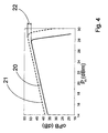
- Fig. 4 shows the optical power budget (oPB) as a function of the total optical power (P in ) comparing a conventionally configured system (solid line 20) to a system configured according to the invention (dashed line 21).
- the total bandwidth is preferred to split only into two separate domains being launched into two dedicated fiber branches.
- the two domains of the so called C-band (typically 1529 - 1562 nm) and the so called L-band (typically 1569 - 1604 nm) are used.
- the dashed line 21 in fig. 4 represents such a system, where both, the C- and the L-band contain 32 channels each.
- the system represented by the solid line 20 is the same as in fig. 3 explained further above.
- Splitting the total bandwidth, while keeping constant the average power per channel would decrease both factors of the tilt-product by a factor of two (half the total bandwidth and half the total optical power would be launched into each branch). However, it is preferred to rather keep constant the total power per fiber.
- the average power per channel can be increased by a factor of two. This is equivalent to an increase of 3 dB, which directly yields the same increase of the optical power budget, as can be read from fig. 4.
- a total profit 22 of about 3.2 dB increase of the optical power budget is achieved.
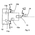
- FIG. 5 schematically shows the setup of a preferred embodiment of the transmission system according to the invention.
- a transmitter terminal 10 is provided with two optical fiber amplifiers 11a and 11b amplifying the input signal of the L-band and of the C-band respectively. These two wavelength domains are launched into two different, dedicated fiber branches 12a and 12b respectively. It is preferred to optimize the optical input power for each branch individually. That means, the maximum launchable optical power, yielding a maximum optical power budget, is fed into each of the fiber branches 12a, 12b, as indicated by the flash-like arrows P L max and P C max .
- the dedicated fiber branches 12a, 12b are embedded in terrestrial fiber cables, preferably in only one terrestrial fiber cable.
- the two wavelength domains are multiplexed together by means of a multiplexer station 13.
- This station 13 must not be closer to the transmitter station 10 than the optical powers of the signals in the two fiber branches 12a, 12b have decreased in a way, that their sum does not exceed the maximum optical power P MUX max launchable into the unique fiber 14, taking into account the multiplexer losses. In fact, there is a certain loss of optical power due to the multiplexing mechanism. Thus, the sum of powers of the C- and the L-band may exceed P MUX max by this amount.
- the multiplexer station 13 is situated close to the beach line of a marine section to be bridged by the fiber line.
- the unique fiber 14 is preferably embedded in a submarine fiber cable.
- a physical transmission network can involve several systems according to the invention in parallel.
- the parallel branches can all be embedded in one cable.
- the multiplexer station 13 would multiplex the wavelenth domains of each pair of branches into one of several, parallel unique fibers beeing embedded in a single cable. It is also possible to split the total bandwidth of wavelengths into more than two domains.
Landscapes
- Physics & Mathematics (AREA)
- Electromagnetism (AREA)
- Engineering & Computer Science (AREA)
- Computer Networks & Wireless Communication (AREA)
- Signal Processing (AREA)
- Optical Communication System (AREA)
Abstract
Description
- Especially in telecommunication optical fiber transmission systems are used to transport optical signals over long distances. In order to increase the amount of information to be transmitted via such a system, the optical signal being launched into the fiber by a transmitter terminal is composed of a number of bit-patterns at different wavelength channels within a total bandwidth of wavelengths. The total launchable bandwidth is limited by the characterizing features of the fiber. Thus, it is a common aim to space the individual wavelength channels as little from each other as possible. 64 channels at a channel separation of 0.8 nm covering a total bandwidth of 52 nm are typical values.
- The optical powers guided by the fiber can be quite high. This is of special interest if long distances across large marine sections have to be bridged. Because of obvious reasons of maintainance submarine repeater stations should be avoided or at least their number should be minimized. This means, that the signal power launched into the fiber has to be maximized to guarantee the receipt of a signal large enough to be reliably detected by the receiver terminal at the far end of the fiber line. However, the maximum total power of the optical signal cannot be increased up to any degree without degrading the signal quality. There are several effects like line broadening, non-linear impairment and channel cross talk, that worsen the signal quality. On the other hand, especially, when the different wavelength channels are very close together, a good signal quality is essential for a reliable de-multiplexing in the receiver terminal.
- The critical figure, which determines the maximum launchable total power is the so called optical power budget. The power budget is defined as the difference between the average optical power per wavelength channel launched into the fiber and the worst sensitivity of the wavelength channels involved. Both, the average power and the sensitivity usually are expressed in dBm. The sensitivity of a wavelength channel is defined as the minimum optical power, that has to be launched into this channel to generate a reliably detectable signal at the input of the receiver. Thus, the optical power budget, usually expressed in dB, can be interpreted as the usable surplus of optical power over the losses due to any kind of signal degradation.
- One of the main degradation effects in signals of high optical power is the depletion of the short wavelength channels in favor of the longer wavelength channels, known as the "stimulated Raman effect", an inelastic stray process. The stimulated Raman effect is explained quantum-mechanically by the virtual excitation of a molecule of the fiber by an incomming photon of a given energy. A second photon of lower energy, i.e. of a longer wavelength, stimulates the deexcitation of the virtual state, i.e. the emission of a photon. The emitted photon has got the same characteristics, namely the same wavelength and the same direction as the stimulating second photon. Thus, the shorter wavelength channels are depleted in favor of the longer wavelength channels by the stimulated Raman effect. Because of this effect, a tilt in the distribution of wavelength channels can be observed. The tilt increases with the distance, the optical signal has passed through the fiber. Fig. 1b schematically shows the distortion of a signal consisting of several wavelength channel of equally distributed signal power, as shown in fig. 1a, where pin is the power launched per channel, pout is the power per channel reaching the receiver and λ is the wavelength. As a partial remedy, it is known to launch a distorted signal, according to fig. 2a, into the fiber. This yields a flat distribution of power at the far end of the fiber line. However, this way of compensation has severe disadvantages.
- The importance of the stimulated Raman effect is, on the one hand, a function of the short wavelength channels's optical power. On the other hand it is depending on the number and strength of the possible deexcitation paths, i.e. the number and power of the longer wavelength channels. If the optical powers are equally distributed amongst the channels, the resulting tilt can mathematically be expressed as the product of the total optical power launched into the fiber times the total bandwidth of wavelengths. This means, the higher the optical power launched to the fiber, the higher is the degradation of the short wavelength channels, i.e. the worse the quality of the signal. It also means, that it is the shortest wavelength channel, whose sensitivity is worst in the system. The optical power budget is, thus, defined relative to this channel. However, if for reasons of compensation, a distorted signal is launched, i.e. the short wavelength channels are overemphasized, the non-linear impairment between the channels becomes stronger.
- In the regime of relatively low total optical powers the optical power budget is governed by linear stray processes. An increase of the optical power launched into the fiber yields an almost linear increase of the optical power budget. This linear behaviour can be read from the left part of the
graph 20 in fig. 3. Fig. 3 shows the experimentally determined optical power budget (oPB) as a function of the total power (Pin) launched into the fiber. The data shown were taken in a system of 64 wavelength channels covering a total bandwidth of 52 nm. At a total optical power of about 27.5 dBm the power budget shows a sharp kink and starts to decrease rapidly from its maximum value of about 49 dB. This kink can be explained by the non-linear effect of stimulated Raman emission, which takes over the government of the power budget at high optical powers. The figure clearly shows the limits of power increase as a means of signal enhancement. The term "maximum total optical power" will be used for the total optical power associated with the maximum optical power budget. - It is a specific object of the invention to provide an optical fiber transmission system, which allows, compared to known systems, eg. document EP 0 863 630, the input of higher optical powers while simultanously increasing the optical power budget.
- To this end the total optical bandwidth to be launched into the fiber line is divided in at least two wavelength domains before launching. Each wavelength domain consists of a multitude of individual wavelength channels. The domains do not overlap. Each one is fed into an individual, dedicated optical fiber, while the optical power budget is optimized for each of the fibers individually. After a certain distance, which is long enough to cause a decrease of the total power below a certain threshold, the signals of the individual fiber branches are multiplexed into one unique fiber guiding the multiplexed signal to the receiver terminal. The threshold mentioned is defined by the maximum total optical power launchable into the unique fiber. This threshold must not be exceeded by the sum of the total optical powers multiplexed together plus multiplexer losses.
- As explained before, the extent of the tilt is depending on the product of the total optical power times the bandwidth covered by this power. If now the total bandwidth is split into several domains and each domain is launched into a dedicated fiber, the bandwidth per fiber - the first factor of the product in question - is reduced. Keeping constant the total power per fiber - the second factor of the product in question - means a respective increase of the average optical power per channel. This increase leads, according to the definition, to a direct increase of the optical power budget. On the other hand, the tilt is still reduced compared to a one-fiber-system. This fact allows a less severe compensation, i.e. the distortion of the power distribution launched into the fiber doesn't have to be as strong as in a one-fiber-system. This means especially, that the optical power of the short wavelength channels can be reduced, which yields a reduction of the non-linear impairment and an improvement of the shortest channel's sensitivity.
- If the different wavelength domains are multiplexed into one unique fiber not earlier than the sum of the total powers of all the branches has decreased below the maximum total power launchable into the unique fiber, the profit of the increased power budget can be preserved. The improvement can easily be seen from fig. 4. Fig. 4 shows the optical power budget (oPB) as a function of the total optical power (Pin) comparing a conventionally configured system (solid line 20) to a system configured according to the invention (dashed line 21).
- It is preferred to split the total bandwidth only into two separate domains being launched into two dedicated fiber branches. For telecommunication most conveniently the two domains of the so called C-band (typically 1529 - 1562 nm) and the so called L-band (typically 1569 - 1604 nm) are used. The dashed
line 21 in fig. 4 represents such a system, where both, the C- and the L-band contain 32 channels each. The system represented by thesolid line 20 is the same as in fig. 3 explained further above. Splitting the total bandwidth, while keeping constant the average power per channel would decrease both factors of the tilt-product by a factor of two (half the total bandwidth and half the total optical power would be launched into each branch). However, it is preferred to rather keep constant the total power per fiber. This means, the average power per channel can be increased by a factor of two. This is equivalent to an increase of 3 dB, which directly yields the same increase of the optical power budget, as can be read from fig. 4. Taking into account the additional profit of lower non-linear impairment due to a smaller tilt-compensation by overemphasizing the short wavelenght channels and also taking into account the inevitable losses of the multiplexing procedure - about 0.8 dB in the example given -, atotal profit 22 of about 3.2 dB increase of the optical power budget is achieved. - Fig. 5 schematically shows the setup of a preferred embodiment of the transmission system according to the invention. A
transmitter terminal 10 is provided with twooptical fiber amplifiers dedicated fiber branches fiber branches dedicated fiber branches fiber branches multiplexer station 13. Thisstation 13 must not be closer to thetransmitter station 10 than the optical powers of the signals in the twofiber branches unique fiber 14, taking into account the multiplexer losses. In fact, there is a certain loss of optical power due to the multiplexing mechanism. Thus, the sum of powers of the C- and the L-band may exceed PMUX max by this amount. Preferably themultiplexer station 13 is situated close to the beach line of a marine section to be bridged by the fiber line. Theunique fiber 14 is preferably embedded in a submarine fiber cable. - It is obvious, that a physical transmission network can involve several systems according to the invention in parallel. The parallel branches can all be embedded in one cable. In this case the
multiplexer station 13 would multiplex the wavelenth domains of each pair of branches into one of several, parallel unique fibers beeing embedded in a single cable. It is also possible to split the total bandwidth of wavelengths into more than two domains.
Claims (8)
- Optical fiber transmission system, comprising a fiber line, and a transmitter terminal (10) for launching an optical signal into the fiber line, said fiber line guiding said optical signal to a receiver terminal, said optical signal being composed of a multitude of bit-patterns at different wavelength channels within a given total bandwidth of wavelengths,
characterized in that :the fiber line consists, in its first section, of at least two branches (12a, 12b),said transmitter (10) for launching into each one of said branches (12a, 12b) a separate part of said optical signal being composed of a sub-multitude of said bit-patterns at neighbouring wavelength channels within non-overlapping bandwidth domains,said parts of said optical signal being multiplexed together into one unique fiber (14) by means of a multiplexer station (13) the length of the branches being such that the power of the signal inputted into the unique fiber (14) is below the maximum total optical power launchable into said unique fiber (14). - Transmission system according to claim 1, characterized in that the full bandwidth of wavelength is split into two domains.
- Transmission system according to claim 2, characterized in that the the C-band of approximately 1529 - 1562 nm and the L-band of approximately 1569 - 1604 nm are used as bandwidth domains launched into dedicated fiber branches (12a, 12b).
- Transmission system according to one of the preceding claims, characterized in that the two fiber branches (12a, 12b) are embedded in the same terrestrial fiber cable.
- Transmission system according to one of the preceding claims, characterized in that the unique fiber (14) is embedded in a submarine fiber cable.
- Transmission system according to one of the preceding claims, characterized in that the multiplexer station (13) is situated close to a beach line.
- Transmission system according to one of the preceding claims, characterized in that several of such transmission systems are used in parallel to constitute a transmission network.
- Transmission system according to claim 7, characterized in that the corresponding fibers of the parallel systems are embedded in the same fiber cable.
Priority Applications (5)
| Application Number | Priority Date | Filing Date | Title |
|---|---|---|---|
| AT01400009T ATE276610T1 (en) | 2001-01-04 | 2001-01-04 | FIBER OPTICAL TRANSMISSION SYSTEM WITH IMPROVED OVERALL INPUT POWER |
| DK01400009T DK1221776T3 (en) | 2001-01-04 | 2001-01-04 | Fiber optic transmission system with improved overall optical input power |
| DE60105540T DE60105540T2 (en) | 2001-01-04 | 2001-01-04 | Fiber optic transmission system with improved total input power |
| EP01400009A EP1221776B1 (en) | 2001-01-04 | 2001-01-04 | Optical fiber transmission system with enhanced total launchable optical power |
| US10/035,303 US20020085804A1 (en) | 2001-01-04 | 2002-01-04 | Optical fiber transmission system with enhanced total launchable optical power |
Applications Claiming Priority (1)
| Application Number | Priority Date | Filing Date | Title |
|---|---|---|---|
| EP01400009A EP1221776B1 (en) | 2001-01-04 | 2001-01-04 | Optical fiber transmission system with enhanced total launchable optical power |
Publications (2)
| Publication Number | Publication Date |
|---|---|
| EP1221776A1 EP1221776A1 (en) | 2002-07-10 |
| EP1221776B1 true EP1221776B1 (en) | 2004-09-15 |
Family
ID=8182592
Family Applications (1)
| Application Number | Title | Priority Date | Filing Date |
|---|---|---|---|
| EP01400009A Expired - Lifetime EP1221776B1 (en) | 2001-01-04 | 2001-01-04 | Optical fiber transmission system with enhanced total launchable optical power |
Country Status (5)
| Country | Link |
|---|---|
| US (1) | US20020085804A1 (en) |
| EP (1) | EP1221776B1 (en) |
| AT (1) | ATE276610T1 (en) |
| DE (1) | DE60105540T2 (en) |
| DK (1) | DK1221776T3 (en) |
Families Citing this family (1)
| Publication number | Priority date | Publication date | Assignee | Title |
|---|---|---|---|---|
| EP4290789A3 (en) * | 2018-08-02 | 2024-03-13 | Cable Television Laboratories, Inc. | System and methods for coherent burst reception |
Family Cites Families (8)
| Publication number | Priority date | Publication date | Assignee | Title |
|---|---|---|---|---|
| US4606020A (en) * | 1984-02-03 | 1986-08-12 | The United States Of America As Represented By The Secretary Of The Army | Efficient design technique for wavelength division multiplexing |
| US6205268B1 (en) * | 1993-05-28 | 2001-03-20 | Lucent Technologies Inc. | Arrangement of optical fiber segments for minimizing effect of nonlinearities |
| US5737460A (en) * | 1995-12-29 | 1998-04-07 | Lucent Technologies Inc. | Applications of solitons in transmission systems employing high launch powers |
| JPH09321740A (en) * | 1996-05-31 | 1997-12-12 | Fujitsu Ltd | Optical amplifier for wavelength division multiplexing |
| US6490064B1 (en) * | 1997-02-14 | 2002-12-03 | Nippon Telegraph And Telephone Corporation | Wavelength division multiplexing optical transmission system |
| CN1082753C (en) * | 1997-03-05 | 2002-04-10 | 富士通株式会社 | Method and apparatus for transmitting wavelength division multiplexed (WDM) signal to reduce effects of stimulated brillouin scattering (SBS) |
| US6614567B1 (en) * | 1998-08-31 | 2003-09-02 | Lucent Technologies Inc. | Apparatus and method for upgrading the capacity of wavelength division multiplexed optical networks |
| US6704511B1 (en) * | 2000-03-27 | 2004-03-09 | Tyco Telecommunications (Us) Inc. | Optical fiber transmission system with noise loaded idler channels |
-
2001
- 2001-01-04 AT AT01400009T patent/ATE276610T1/en not_active IP Right Cessation
- 2001-01-04 DE DE60105540T patent/DE60105540T2/en not_active Expired - Fee Related
- 2001-01-04 DK DK01400009T patent/DK1221776T3/en active
- 2001-01-04 EP EP01400009A patent/EP1221776B1/en not_active Expired - Lifetime
-
2002
- 2002-01-04 US US10/035,303 patent/US20020085804A1/en not_active Abandoned
Also Published As
| Publication number | Publication date |
|---|---|
| DE60105540D1 (en) | 2004-10-21 |
| EP1221776A1 (en) | 2002-07-10 |
| US20020085804A1 (en) | 2002-07-04 |
| ATE276610T1 (en) | 2004-10-15 |
| DK1221776T3 (en) | 2005-01-10 |
| DE60105540T2 (en) | 2005-09-29 |
Similar Documents
| Publication | Publication Date | Title |
|---|---|---|
| US6961522B1 (en) | Automatic raman gain and tilt control for ultra-long-distance dense WDM optical communication system | |
| Puttnam et al. | 301 Tb/s E, S, C+ L-band transmission over 212 nm bandwidth with E-band bismuth-doped fiber amplifier and gain equalizer | |
| EP1248392B1 (en) | Optical amplifier device and bidirectional wavelength division multiplexing optical communication system using the same | |
| US6532101B2 (en) | System and method for wide band Raman amplification | |
| US7200333B2 (en) | Optical communication apparatus, system, and method that properly compensate for chromatic dispersion | |
| US7085039B2 (en) | Hybrid Raman/erbium-doped fiber amplifier and transmission system with dispersion map | |
| EP1317083B1 (en) | Optical transmission system and optical transmission method utilizing Raman amplification | |
| JP3779691B2 (en) | Broadband erbium-doped optical fiber amplifier and wavelength division multiplexing optical transmission system employing the same | |
| JP2003524931A (en) | Multi-wavelength optical communication system with optical amplifier | |
| US6317238B1 (en) | Chromatic dispersion management for optical wavelength division multiplexed transmission systems | |
| US7075709B2 (en) | Optical transmission system, optical repeater, and optical transmission method | |
| de Jauregui Ruiz et al. | 66.8 Tb/s real-time C+ L unrepeatered transmission over 301 km using forward and backward Raman amplification | |
| US7043112B2 (en) | Optical wavelength-multiplexing technique | |
| US6868203B2 (en) | Optical transmission system | |
| US20210257802A1 (en) | Multimode Optical Amplifier | |
| CN1787407B (en) | Raman Optical Amplifier with Parallel Structure | |
| EP1221776A1 (en) | Optical fiber transmission system with enhanced total launchable optical power | |
| CN109075864A (en) | Via the ROPA in the same direction for the separation optical fiber supply power for transmitting data in opposite direction | |
| US7197247B2 (en) | WDM optical communication system | |
| JP3866592B2 (en) | Optical transmission system using Raman amplification | |
| US20020044339A1 (en) | Optical transmission system with reduced raman effect depletion | |
| JP3596403B2 (en) | Optical wavelength division multiplex transmitter, optical wavelength division multiplex receiver, optical repeater, and optical wavelength division multiplex transmission system | |
| JP2000077757A (en) | Optical amplifier, optical transmission device, and optical transmission system | |
| US20040100683A1 (en) | Raman amplifier | |
| US7038839B1 (en) | Optical signal amplification using multiple backward-pumping systems |
Legal Events
| Date | Code | Title | Description |
|---|---|---|---|
| PUAI | Public reference made under article 153(3) epc to a published international application that has entered the european phase |
Free format text: ORIGINAL CODE: 0009012 |
|
| AK | Designated contracting states |
Kind code of ref document: A1 Designated state(s): AT BE CH CY DE DK ES FI FR GB GR IE IT LI LU MC NL PT SE TR |
|
| AX | Request for extension of the european patent |
Free format text: AL;LT;LV;MK;RO;SI |
|
| 17P | Request for examination filed |
Effective date: 20030110 |
|
| AKX | Designation fees paid |
Designated state(s): AT BE CH CY DE DK ES FI FR GB GR IE IT LI LU MC NL PT SE TR |
|
| 17Q | First examination report despatched |
Effective date: 20030220 |
|
| GRAP | Despatch of communication of intention to grant a patent |
Free format text: ORIGINAL CODE: EPIDOSNIGR1 |
|
| GRAS | Grant fee paid |
Free format text: ORIGINAL CODE: EPIDOSNIGR3 |
|
| GRAA | (expected) grant |
Free format text: ORIGINAL CODE: 0009210 |
|
| AK | Designated contracting states |
Kind code of ref document: B1 Designated state(s): AT BE CH CY DE DK ES FI FR GB GR IE IT LI LU MC NL PT SE TR |
|
| PG25 | Lapsed in a contracting state [announced via postgrant information from national office to epo] |
Ref country code: TR Free format text: LAPSE BECAUSE OF FAILURE TO SUBMIT A TRANSLATION OF THE DESCRIPTION OR TO PAY THE FEE WITHIN THE PRESCRIBED TIME-LIMIT Effective date: 20040915 Ref country code: NL Free format text: LAPSE BECAUSE OF FAILURE TO SUBMIT A TRANSLATION OF THE DESCRIPTION OR TO PAY THE FEE WITHIN THE PRESCRIBED TIME-LIMIT Effective date: 20040915 Ref country code: LI Free format text: LAPSE BECAUSE OF FAILURE TO SUBMIT A TRANSLATION OF THE DESCRIPTION OR TO PAY THE FEE WITHIN THE PRESCRIBED TIME-LIMIT Effective date: 20040915 Ref country code: FI Free format text: LAPSE BECAUSE OF FAILURE TO SUBMIT A TRANSLATION OF THE DESCRIPTION OR TO PAY THE FEE WITHIN THE PRESCRIBED TIME-LIMIT Effective date: 20040915 Ref country code: CH Free format text: LAPSE BECAUSE OF FAILURE TO SUBMIT A TRANSLATION OF THE DESCRIPTION OR TO PAY THE FEE WITHIN THE PRESCRIBED TIME-LIMIT Effective date: 20040915 Ref country code: BE Free format text: LAPSE BECAUSE OF FAILURE TO SUBMIT A TRANSLATION OF THE DESCRIPTION OR TO PAY THE FEE WITHIN THE PRESCRIBED TIME-LIMIT Effective date: 20040915 Ref country code: AT Free format text: LAPSE BECAUSE OF FAILURE TO SUBMIT A TRANSLATION OF THE DESCRIPTION OR TO PAY THE FEE WITHIN THE PRESCRIBED TIME-LIMIT Effective date: 20040915 |
|
| REG | Reference to a national code |
Ref country code: GB Ref legal event code: FG4D Ref country code: CH Ref legal event code: EP |
|
| REG | Reference to a national code |
Ref country code: IE Ref legal event code: FG4D |
|
| REF | Corresponds to: |
Ref document number: 60105540 Country of ref document: DE Date of ref document: 20041021 Kind code of ref document: P |
|
| PG25 | Lapsed in a contracting state [announced via postgrant information from national office to epo] |
Ref country code: SE Free format text: LAPSE BECAUSE OF FAILURE TO SUBMIT A TRANSLATION OF THE DESCRIPTION OR TO PAY THE FEE WITHIN THE PRESCRIBED TIME-LIMIT Effective date: 20041215 Ref country code: GR Free format text: LAPSE BECAUSE OF FAILURE TO SUBMIT A TRANSLATION OF THE DESCRIPTION OR TO PAY THE FEE WITHIN THE PRESCRIBED TIME-LIMIT Effective date: 20041215 |
|
| PG25 | Lapsed in a contracting state [announced via postgrant information from national office to epo] |
Ref country code: ES Free format text: LAPSE BECAUSE OF FAILURE TO SUBMIT A TRANSLATION OF THE DESCRIPTION OR TO PAY THE FEE WITHIN THE PRESCRIBED TIME-LIMIT Effective date: 20041226 |
|
| PGFP | Annual fee paid to national office [announced via postgrant information from national office to epo] |
Ref country code: GB Payment date: 20041229 Year of fee payment: 5 |
|
| PG25 | Lapsed in a contracting state [announced via postgrant information from national office to epo] |
Ref country code: LU Free format text: LAPSE BECAUSE OF NON-PAYMENT OF DUE FEES Effective date: 20050104 Ref country code: IE Free format text: LAPSE BECAUSE OF NON-PAYMENT OF DUE FEES Effective date: 20050104 Ref country code: CY Free format text: LAPSE BECAUSE OF FAILURE TO SUBMIT A TRANSLATION OF THE DESCRIPTION OR TO PAY THE FEE WITHIN THE PRESCRIBED TIME-LIMIT Effective date: 20050104 |
|
| PGFP | Annual fee paid to national office [announced via postgrant information from national office to epo] |
Ref country code: DE Payment date: 20050106 Year of fee payment: 5 |
|
| PGFP | Annual fee paid to national office [announced via postgrant information from national office to epo] |
Ref country code: FR Payment date: 20050111 Year of fee payment: 5 Ref country code: DK Payment date: 20050111 Year of fee payment: 5 |
|
| PG25 | Lapsed in a contracting state [announced via postgrant information from national office to epo] |
Ref country code: MC Free format text: LAPSE BECAUSE OF NON-PAYMENT OF DUE FEES Effective date: 20050131 |
|
| ET | Fr: translation filed | ||
| REG | Reference to a national code |
Ref country code: CH Ref legal event code: PL |
|
| NLV1 | Nl: lapsed or annulled due to failure to fulfill the requirements of art. 29p and 29m of the patents act | ||
| PLBE | No opposition filed within time limit |
Free format text: ORIGINAL CODE: 0009261 |
|
| STAA | Information on the status of an ep patent application or granted ep patent |
Free format text: STATUS: NO OPPOSITION FILED WITHIN TIME LIMIT |
|
| 26N | No opposition filed |
Effective date: 20050616 |
|
| REG | Reference to a national code |
Ref country code: IE Ref legal event code: MM4A |
|
| PG25 | Lapsed in a contracting state [announced via postgrant information from national office to epo] |
Ref country code: GB Free format text: LAPSE BECAUSE OF NON-PAYMENT OF DUE FEES Effective date: 20060104 |
|
| PG25 | Lapsed in a contracting state [announced via postgrant information from national office to epo] |
Ref country code: FR Free format text: LAPSE BECAUSE OF NON-PAYMENT OF DUE FEES Effective date: 20060131 Ref country code: DK Free format text: LAPSE BECAUSE OF NON-PAYMENT OF DUE FEES Effective date: 20060131 |
|
| PGFP | Annual fee paid to national office [announced via postgrant information from national office to epo] |
Ref country code: IT Payment date: 20060131 Year of fee payment: 6 |
|
| PG25 | Lapsed in a contracting state [announced via postgrant information from national office to epo] |
Ref country code: DE Free format text: LAPSE BECAUSE OF NON-PAYMENT OF DUE FEES Effective date: 20060801 |
|
| REG | Reference to a national code |
Ref country code: DK Ref legal event code: EBP |
|
| GBPC | Gb: european patent ceased through non-payment of renewal fee |
Effective date: 20060104 |
|
| REG | Reference to a national code |
Ref country code: FR Ref legal event code: ST Effective date: 20060929 |
|
| PG25 | Lapsed in a contracting state [announced via postgrant information from national office to epo] |
Ref country code: PT Free format text: LAPSE BECAUSE OF NON-PAYMENT OF DUE FEES Effective date: 20050215 |
|
| PG25 | Lapsed in a contracting state [announced via postgrant information from national office to epo] |
Ref country code: IT Free format text: LAPSE BECAUSE OF NON-PAYMENT OF DUE FEES Effective date: 20070104 |