EP1221736A2 - Antenna structure and mobile terminal having antenna structure - Google Patents
Antenna structure and mobile terminal having antenna structure Download PDFInfo
- Publication number
- EP1221736A2 EP1221736A2 EP01131027A EP01131027A EP1221736A2 EP 1221736 A2 EP1221736 A2 EP 1221736A2 EP 01131027 A EP01131027 A EP 01131027A EP 01131027 A EP01131027 A EP 01131027A EP 1221736 A2 EP1221736 A2 EP 1221736A2
- Authority
- EP
- European Patent Office
- Prior art keywords
- antenna
- mobile terminal
- flexible substrate
- matching circuit
- antenna element
- Prior art date
- Legal status (The legal status is an assumption and is not a legal conclusion. Google has not performed a legal analysis and makes no representation as to the accuracy of the status listed.)
- Withdrawn
Links
Images






Classifications
-
- H—ELECTRICITY
- H01—ELECTRIC ELEMENTS
- H01Q—ANTENNAS, i.e. RADIO AERIALS
- H01Q11/00—Electrically-long antennas having dimensions more than twice the shortest operating wavelength and consisting of conductive active radiating elements
- H01Q11/02—Non-resonant antennas, e.g. travelling-wave antenna
- H01Q11/08—Helical antennas
-
- H—ELECTRICITY
- H01—ELECTRIC ELEMENTS
- H01Q—ANTENNAS, i.e. RADIO AERIALS
- H01Q1/00—Details of, or arrangements associated with, antennas
- H01Q1/12—Supports; Mounting means
- H01Q1/22—Supports; Mounting means by structural association with other equipment or articles
- H01Q1/24—Supports; Mounting means by structural association with other equipment or articles with receiving set
- H01Q1/241—Supports; Mounting means by structural association with other equipment or articles with receiving set used in mobile communications, e.g. GSM
- H01Q1/242—Supports; Mounting means by structural association with other equipment or articles with receiving set used in mobile communications, e.g. GSM specially adapted for hand-held use
- H01Q1/243—Supports; Mounting means by structural association with other equipment or articles with receiving set used in mobile communications, e.g. GSM specially adapted for hand-held use with built-in antennas
- H01Q1/244—Supports; Mounting means by structural association with other equipment or articles with receiving set used in mobile communications, e.g. GSM specially adapted for hand-held use with built-in antennas extendable from a housing along a given path
-
- H—ELECTRICITY
- H01—ELECTRIC ELEMENTS
- H01Q—ANTENNAS, i.e. RADIO AERIALS
- H01Q1/00—Details of, or arrangements associated with, antennas
- H01Q1/36—Structural form of radiating elements, e.g. cone, spiral, umbrella; Particular materials used therewith
- H01Q1/38—Structural form of radiating elements, e.g. cone, spiral, umbrella; Particular materials used therewith formed by a conductive layer on an insulating support
-
- H—ELECTRICITY
- H01—ELECTRIC ELEMENTS
- H01Q—ANTENNAS, i.e. RADIO AERIALS
- H01Q9/00—Electrically-short antennas having dimensions not more than twice the operating wavelength and consisting of conductive active radiating elements
- H01Q9/04—Resonant antennas
- H01Q9/30—Resonant antennas with feed to end of elongated active element, e.g. unipole
- H01Q9/42—Resonant antennas with feed to end of elongated active element, e.g. unipole with folded element, the folded parts being spaced apart a small fraction of the operating wavelength
Definitions
- the present invention relates to an antenna structure and a mobile terminal having the particular antenna structure, particularly, to an antenna structure adapted for use in, for example, a cellular, mobile or PHS (Personal Handy-Phone System) phone or terminal.
- a cellular, mobile or PHS Personal Handy-Phone System
- Mobile phones or terminals are generally provided in general with an antenna, for receiving a high frequency signal from a radio station and for transmission a high frequency signal to the radio station.
- the antenna employs, in general, an antenna structure constructed to enable extension and retraction of antenna, and is capable of receiving a high frequency signal in the retracted state.
- a helical first antenna section having a first contact point section is arranged in the mobile terminal body, and a second antenna section having a second contact point section, connected to the first antenna in the longitudinal direction, is housed extensible in the mobile terminal body.
- the helical section alone of the first antenna protrudes from the mobile terminal body, and the first contact point section of the first antenna is connected to the power supply section, with the result that power is supplied to the first antenna section.
- the second contact point section of the second antenna section is connected to the second contact point section, with the result that power is supplied to the second antenna section. It follows that a high frequency signal can be transmitted and received between the mobile terminal and the radio station whether the antenna is extended or retracted.
- a monopole antenna having a length of ⁇ /4, 3 ⁇ /8 and 5 ⁇ /8, where ⁇ represents the wavelength of the high frequency signal that is transmitted or received.
- the self-resonant type can be applied to a so-called "viewer type” mobile terminal on which a large liquid crystal screen is mounted so as to make it possible for the user to transmit and receive data, such as character data, still and moving image data, while observing the liquid crystal screen.
- the antenna is preferably coupled to the radio frequency circuit section via a matching circuit of weak magnetic field coupling type to reduce the Q factor and to increase the bandwidth.
- the antenna is more preferably coupled to the radio frequency circuit via a matching circuit of ⁇ /2 capacitive-coupling type, which has a line of ⁇ /4.
- This self-resonant type antenna can realize a characteristics having two resonant points and a more broader bandwidth, which is referred to herein after as a ⁇ /2 capacitive-coupling antenna.
- a retractable antenna there is known a bottom helical structure in which a helical antenna as the first antenna is fixed in the housing of the mobile terminal, when the extensible antenna as the second antenna is pulled up from the housing.
- a ⁇ /2 capacitive-coupling antenna having the bottom helical structure is disclosed in USP 5,717,409, issued Feb. 10, 1998, Garner et al, which has a configuration as shown in FIG. 1.
- a radio transmission section 3 is arranged within a terminal body 2.
- An antenna cap 5C is erected on the terminal body 2, and an antenna element 5D constituting an antenna in the retracted state is spirally arranged in the axial direction of the antenna within the antenna cap 5C.
- a cylindrical frame 5F having a spiral matching circuit element 5E formed on the circumferential wall is coaxially arranged within the antenna element 5D.
- An extensible antenna 5G (movable in the direction denoted by the arrows A and B) when extended, is capable of being housed in the cylindrical frame 5F with a sleeve 5H interposed therebetween. If the antenna 5G is extended from the housing or terminal body 2, the antenna 5G is capacitively coupled with the matching circuit element 5E via a capacitive coupling section 5I of the sleeve 5H. Also, if the antenna 5G is housed in the terminal body 2, the antenna element 5D, not the antenna 5G is capacitively coupled with the matching circuit element 5E.
- the construction of the conventional antenna is highly complex.
- An object of the present invention is to provide an antenna structure simple in structure and capable of increasing the bandwidth and increasing the gain, and to provide a mobile terminal equipped with the particular antenna structure.
- a mobile terminal comprising:
- a mobile terminal comprising:
- FIGS. 2 and 3 collectively show an antenna structure according to one embodiment of the present invention, and a mobile terminal equipped with the particular antenna structure. Specifically, FIG. 2 shows the antenna is in a retracted state in a body 10 of the mobile terminal, and FIG. 3 shows the extended state of the antenna.
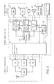
- a printed circuit board 9 having a radio transmission section 1, a base band section 2, and an input-output section 3 formed thereon as shown in FIG. 4 is arranged in the terminal body 10 as shown in FIGS. 2 and 3.
- a high frequency radio signal transmitted from a radio station is received by a retractable antenna 11, and supplied to a receiver (RX) 13 through a duplexer (DUP) 12.
- the receiver 13 includes a high frequency amplifier, a frequency converter and a demodulator.
- the radio transmission signal is so amplified as to suppress a generation of noises in a low noise high frequency amplifier and is mixed, in the frequency converter, with a local oscillation signal generated from a frequency synthesizer (SYN) 14 and the mixed signal is down-converted into an intermediate frequency signal or a base band signal.
- the output signal is demodulated into a digital signal by the demodulator.
- the demodulation scheme is, for example, an orthogonal demodulation scheme corresponding to a QPSK (Quadrature PSK) scheme and a spectrum de-spreading scheme using a diffusion code.
- the frequency of the local oscillation signal generated from the frequency synthesizer 14 noted above is controlled by a main control section 21 arranged in the base band section 2.
- the demodulation signal generated from the demodulator is supplied to the base band section 2.
- the base band section 2 comprises the main control section 21, a demultiplexer 22, a voice codec 23, a multimedia processor 24, an LCD controller 25, and a memory section 26.
- the demodulation signal represents control information or a multimedia signal. If the demodulation signal represents multimedia information, the demodulation signal is supplied into a multiplex separating section 22 and separated into voice data and image data. The voice data is input to the voice codec 23 so as to be restored into voice signals. As a result, the voice signals are converted into voice, which is generated from a loud speaker 32 included in the input-output section 3. On the other hand, the image data is supplied to the multimedia processor 24 so as to be processed to generate image signals. The image signals thus regenerated are supplied to an LCD 34 included in the input-output section 3 via the LCD control section 25, with the result that an image is displayed on the LCD 34.
- the received image data is stored in a RAM arranged in the main control section 21. Also, various information denoting the operating state of the apparatus, which is generated from the main control section 21, e.g., the telephone book, the detected electric field intensity of the received signal, and the residual amount of the battery, is also displayed on the LCD 34.
- the speech signal of the user generated from a microphone 31 included in the input-output section 3 is supplied to the voice codec 23 of the base band section 2 so as to be coded as voice and, then, supplied to the demultiplexer 22.
- an image signal generated from a camera (CAM) 33 is supplied to the multimedia processor 24 included in the base band section 2 so as to be subjected to a coding process and, then, supplied to the demultiplexer 22.
- the coded voice data and the coded image data are multiplexed in a predetermined format.
- the transmission data thus multiplexed is supplied from the main control section 21 into a transmitting circuit (TX) 15 included in the radio transmission section 1.
- the transmitting circuit 15 includes a modulator, a frequency converter and a transmission power amplifier.
- the transmission data is modulated into digital signals in the modulator and, then, mixed in the frequency converter, with a local oscillation signal generated from the frequency synthesizer 14 to down convert into a radio transmission frequency signal.
- a QPSK scheme and a spectrum diffusion scheme using a diffusion code are employed as the modulation scheme.
- the radio transmission frequency signal thus generated is amplified to a predetermined level by the power amplifier, supplied to the antenna 11 through the duplexer 12 and, then, transmitted to a radio station (not shown) from the antenna 11.
- an illuminating device 36 for illuminating the LCD 34 and a key input section 35 during operation.
- the illuminating device 36 is called, for example, a "back light” or "illumination”.
- the retractable antenna 11 for transmission and receiving a mobile terminal signal to and from the radio station referred to previously will now be described.
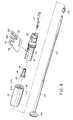
- a cylindrical antenna cap 110 supporting the antenna and made of a non-metallic material is fixed to the body 10 of the mobile terminal in an upward-protruding manner.
- a cylindrical frame 111 made of a non-metallic material is housed in the antenna cap 110.
- An elastic engaging section 112 is mounted to the frame 111.
- the elastic engaging section 112 (not shown in FIGS. 2 and 3) is elastically engaged with the terminal body 10 so as to permit the antenna cap 110 to be mounted to the terminal body 10.
- a slot 113 (not shown in FIGS. 2 and 3) is formed in the cylindrical frame 111, and a cylindrical sleeve 114 made of a metallic material is inserted into the cylindrical frame 111.
- a flange-like connecting section 115 is formed in the proximal end portion of the sleeve 114 in a manner to correspond to the slot 113 of the frame 111, and a power supply pin coupling section 116 for supplying the transmission power is formed in the distal end portion of the sleeve 114.
- One end of a power supply pin 117 is coupled with the power supply pin coupling section 116, and the other end of the power supply pin 117 is electrically connected to the DUP 12 in the radio transmission section 1 formed on the printed circuit board 9.
- a flexible substrate 118 is wound about the cylindrical frame 111 by utilizing the flexibility of the substrate 118.
- a power supply terminal 121 of the matching circuit 120 is electrically connected to the connecting section 116 of the sleeve 114 through the slot 113, and the sleeve 114 is electrically connected via the power supply pin 117 to the DUP 12 of the radio transmission section 1 formed on the printed circuit board 9.
- the meandering antenna element 119 is formed on the flexible substrate 118 such that the total length of the antenna element 119 is equal to ⁇ /2. Also formed on the flexible substrate 118 is the matching circuit 120 such that the sum of the lengths of the matching circuit 120 and the length of the power supply pin 117 is equal to ⁇ /4. Further, a capacitive coupling section 124 for capacitive-coupling between the matching circuit 120 and the meandering antenna element 119 is formed on the flexible substrate 118 so as to be positioned between the matching circuit 120 and the antenna element 119.
- a rod-like antenna 122 corresponding to a first antenna is retractably arranged in the sleeve 114 (movable in the direction denoted by the arrows A and B in FIGS. 2 and 3).
- a linear antenna element 123 having a length corresponding to ⁇ /2 is coaxially arranged on the rod-like antenna 122 with the meandering antenna element 119 formed on the flexible substrate 118.
- the proximal end of the linear antenna element 123 is electrically connected to the capacitive coupling section 124 formed on the flexible substrate 118, with the result that the linear antenna element 124 is electrically connected to the matching circuit 120.
- the rod-like antenna 122 is provided at one end with a first stopper 125 which is abutted to the top portion of the antenna cap 110 to regulate the retracted position of the rod-like antenna 122 when retracted, and is also provided at the other end with a second stopper 126 which is also abutted to the bottom portion of the frame 111 to regulate the extended position of the rod-like antenna 122 when the rod-like antenna 122 is extended.
- the first stopper 125 abuts against the portion of the antenna cap 110 so as to permit the rod-like antenna body 122 to be housed in the terminal body 10.
- the edge portion on the upper side of the linear antenna element 123 of the rod-like antenna 122 is positioned away from the capacitive coupling section 124 of the matching circuit 120 formed on the flexible substrate 118 so that the capacitive coupling section 124 is electrically disconnected. Also, when the antenna is housed in the terminal body 10, the meandering antenna element 119 on the flexible substrate 118 is electrically connected to the matching circuit 120 via the capacitive coupling section 124.
- the meandering antenna element 119 is electrically connected to the DUP 12 included in the radio transmission section 1 formed on the printed circuit board through the matching circuit 120, the sleeve 114 and the power supply pin 117, so as to execute the transmission-reception of the signal by the so-called " ⁇ /2 capacitive coupling antenna".
- the second stopper 126 abuts against the edge portion of the frame 111, thereby limiting the extension of the rod-like antenna 122.
- the lower edge portion of the linear antenna element 123 of the rod-like antenna 122 is electrically connected to the capacitive coupling section 124 of the matching circuit 120 formed on the flexible substrate 118 so as to be electrically connected to the DUP 12 included in the radio transmission section 1 on the printed circuit board 9 via the matching circuit 120, the sleeve 114 and the power supply pin 117, thereby executing the transmission-reception of the signal by the ⁇ /2 capacitive coupling antenna.
- the meandering antenna element 119 on the flexible substrate 118 is electrically connected to the matching circuit 120 via the capacitive coupling section 124.
- the rod-like antenna 122 is substantially connected electrically to the matching circuit 120 via the capacitive coupling section 124 so as to permit the linear antenna element 123 of the rod-like antenna 122 to execute transmission-reception of the signal.
- the flexible substrate 118 having the meandering antenna element 119 and the matching circuit 120 formed thereon is mounted within the antenna cap 110 so as to be incorporated in the terminal body 10.
- the rod-like antenna 122, arranged protrusibly within the flexible substrate 118 is housed protrusibly within the terminal body 10, so as to achieve or release the capacitive coupling between the linear antenna element 123 of the rod-like antenna 122 and the matching circuit 120 on the flexible substrate 118 in accordance with the extension or retraction of the rod-like antenna 122.
- the linear antenna element 123 performs the function of the retractable antenna in cooperation with the meandering antenna element 119 formed on the flexible substrate 118.
- the flexible substrate 118 having the meandering antenna element 119 and the matching circuit 120 formed thereon is wound about the terminal body 10 with the antenna cap 110 interposed therebetween.
- the retractable antenna structure can be achieved by the simple construction that the rod-like antenna 122 is simply housed in the flexible substrate 118, which is wound to form the bottom helical structure of the ⁇ /2 capacitive coupling type, permitting an increase in the bandwidth and gain.
- the flexible substrate 118 having the meandering antenna element 119 and the matching circuit 120 formed thereon is wound within the antenna cap 110 so as to be mounted in the terminal body 10.
- the rod-like antenna 122 arranged protrusibly within the flexible substrate 118 is housed protrusibly so as to achieve or release the capacitive coupling between the linear antenna element 123 of the rod-like antenna 122 and the matching circuit 120 formed on the flexible substrate 118 in accordance with the extension and retraction of the rod-like antenna 122. It follows that the retractable antenna structure is capable of transmission-reception of the signal in cooperation with the meandering antenna element 119 formed on the flexible substrate 118.
- a retractable antenna of the capacitive coupling type with the bottom helical structure of the ⁇ /2 which permits increasing the band width and the gain, can be achieved by a simple construction in which the flexible substrate 118, having the meandering antenna element 119 and the matching circuit 120 formed thereon, is arranged in the antenna cap 110 interposed therebetween, and the rod-like antenna 122 is retractably housed within the wound flexible substrate 118.
- the so-called "viewer type" terminal structure for performing the transmission-reception of data such as the still and moving image data.
- FIGS. 6 to 14B The mobile terminal structures equipped with the antenna structures according to other embodiments of the present invention will now be described with reference to FIGS. 6 to 14B.
- the same members of the mobile terminal structure as shown in FIGS. 2 to 5 are denoted by the same reference numerals so as to avoid an overlapping description.
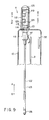
- the linear antenna element 123 extends within the rod-like antenna 122 so as to reach a region in the vicinity of the second stopper 126.
- any of the linear antenna element 123 and the meandering antenna element 119 formed on the flexible substrate 118 is coupled by the capacitive coupling with the matching circuit 120 whether the rod-like antenna 122 is extended or housed in the terminal body 10.
- the capacitance is set to permit the capacitive coupling between the linear antenna element 123 and the matching circuit 120 to be substantially equal to the capacitive coupling between the meandering antenna element 119 formed on the flexible substrate 118 and the matching circuit 120.
- the linear antenna element 123 it is possible for the linear antenna element 123 to be coupled together with the meandering antenna element 119 with the matching circuit 120 formed on the flexible substrate 118, by capacitive coupling when the rod-like antenna 122 is extended or retracted in the terminal body 10.
- the user interface section such as the microphone 31 and the loud speaker 32 is arranged on the front side of the mobile terminal body 10
- the flexible substrate 118 is arranged at the rear side of the antenna cap 110, the rear side corresponding to the opposite side of the front side of the mobile terminal body 10.
- the meandering antenna element 119 and the matching circuit 120 is arranged in the space on the rear side of the antenna cap 110 relative to the antenna axis, and the flexible substrate 118 is positioned within the antenna cap fixed to the terminal body 10 such that the flexible substrate 118 is positioned as remotely as possible from the user.
- the terminal body 10 it is possible to satisfy the miniaturization of the terminal body 10 and to set maximum the distance L from the user making the telephone conversation, by utilizing the meandering antenna element 119 and the matching circuit 120 formed on the flexible substrate 118, the loud speaker 32, etc., under the state that the rod-like antenna 122 is housed in the terminal body 10.
- FIGS. 11 and 12 collectively show a mobile terminal equipped with an antenna structure according to another embodiment of the present invention.
- the flexible substrate 118 is mounted within the antenna cap 110 such that the angle ⁇ made between an axis Ox of the meandering antenna element 119 and the matching circuit 120 and a reference axis Oref parallel to the antenna axis Oc falls within a range of between about 45° and 90°.
- the angle ⁇ noted above should be about 60°.
- the reference axis Oref is substantially coincident with the direction of the principal polarized electromagnetic radiation, as shown in FIG. 12, although the situation depends on the mode of use of the mobile terminal.
- the meandering antenna element 119 and the matching circuit 120 are inclined by at least about 45° relative to the antenna axis, as shown in FIG. 12.
- the meandering antenna element 119 faces in the direction of the principal polarized electromagnetic radiation (zenith) so as to make it possible to receive with a high efficiency vertically-polarized electromagnetic radiation waves transmitted from the radio station, or to transmit with a high efficiency, the vertically-polarized electromagnetic wave to the radio station. It follows that it is possible to realize a simple and a highly efficient telephone by using the meandering antenna element 119.
- the meandering antenna element 119 and the matching circuit 120 are formed on a single flexible substrate 118.
- the meandering antenna element 119 alone is formed on the flexible substrate 118, and the meandering antenna element 119 is coupled directly with the sleeve 114 through the capacitive coupling.
- one end of the power supply pin 117 connected to the radio transmission section 1 is electrically connected to the sleeve 114 so that the power supply pin 117 performs the function of the matching circuit 120.
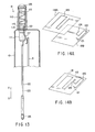
- FIG. 14A shows another embodiment of the present invention.
- two flexible substrates 118A and 118B having the meandering antenna element 119 and the matching circuit 120 formed thereon, respectively, are bonded to each other with the positions of the substrates 118A and 118B aligned appropriately, in place of using a single flexible substrate 118 having both the meandering antenna element 119 and the matching circuit 120 formed thereon.
- the capacitive coupling section 124 is formed in the bonding portion of the flexible substrates 118A and 118B.
- FIG. 14B shows still another embodiment of the present invention.
- the meandering antenna element 119 is formed on one surface of a single flexible substrate 118
- the matching circuit 120 is formed on the other surface of the flexible substrate 118.
- each of the antenna element 119 and the matching circuit 120 are formed on the flexible substrate 118 in a meandering pattern.
- the patterns of the antenna element 119 and the matching circuit 120 need not be limited to the meandering pattern. It is possible for the antenna element 119 and the matching circuit 120 to be of various other patterns.
- the technical idea of the present invention is applied to the retractable antenna of the bottom helical structure.
- the technical idea of the present invention is also possible to apply the technical idea of the present invention to the top helical structure constructed to pull up the antennas including the antenna used when the antenna is extended or retracted, with substantially the same effect.
Landscapes
- Engineering & Computer Science (AREA)
- Computer Networks & Wireless Communication (AREA)
- Support Of Aerials (AREA)
- Details Of Aerials (AREA)
- Variable-Direction Aerials And Aerial Arrays (AREA)
- Telephone Set Structure (AREA)
Abstract
Description
Claims (15)
- An antenna structure arranged in a mobile terminal having a body (10) including a holding section (110) configured to hold an antenna structure (11) and a mobile terminal circuit section (9) housed in said body (10), characterized by comprising:a first flexible substrate (118, 118A) mounted within said holding section (110);a meander-shaped antenna pattern (119) formed on the flexible substrate (118, 118A);a matching circuit element (120) configured to substantially match the impedances of said antenna pattern (119) and a mobile terminal circuit section (9); anda capacitive coupling element (124) configured to achieve a capacitive coupling between said antenna pattern (119) and said matching circuit (120).
- The antenna structure according to claim 1, characterized in that said matching circuit element (120) and said capacitive coupling element (124) are formed on said flexible substrate (118).
- The antenna structure according to claim 1, characterized by further comprising a second flexible substrate (118B) arranged within said holding section (110), said matching circuit element (120) being formed on said second flexible substrate and said capacitive coupling element (124) being formed between said first and second flexible substrates (118A, 118B).
- An antenna structure arranged in a mobile terminal having a body (10) including a holding section (110) configured to hold an antenna structure (11) and a mobile terminal circuit section (9) housed in said body (10), characterized by comprising:a first antenna element (123) extending substantially linearly;an antenna support mechanism (122) configured to support the first antenna element (123), arranged within an antenna holding section (110), and to permit the first antenna element (123) to be withdrawn from the body (10) of a mobile terminal and to be returned into said body (10) so as to be housed in said body (10);a flexible substrate (118, 118A) mounted within said holding section (110) and arranged around said first antenna element (123) withdrawn from said body (10);a second antenna pattern (119) formed bent on said flexible substrate (118, 118A);a matching circuit (120) configured to mach the impedance of said second antenna element (119) with the impedance of the mobile terminal section (9) of the second antenna pattern (119); anda capacitive coupling element (124) configured to couple the first antenna element (123) and the second antenna pattern (119) with said matching element (120).
- The antenna structure according to claim 4, characterized in that said matching circuit (120) is formed on said flexible substrate (118, 118A).
- The antenna structure according to claim 4, characterized in that said capacitive coupling element (124) couples said first antenna element (123) with said matching circuit (120) when said first antenna element (123) is withdrawn from said body (10), and releases the capacitive coupling between said first antenna element (123) and said matching circuit (120) when the first antenna (123) is housed in said body (10).
- The antenna structure according to claim 4, characterized in that said capacitive coupling element (124) couples said second antenna pattern (119) with said matching circuit (120) when said first antenna element (123) is housed in said body (10).
- A mobile terminal, characterized by comprising:a first antenna element (123) extending substantially linearly along an antenna axis;a body (10) including a housing section (110) for housing said first antenna element (123);an antenna support mechanism (110) configured to support said first antenna element (123), housed in said housing section (110), and to permit said first antenna element (123) to be withdrawn from the body (10) of a mobile terminal along the antenna axis and to be retracted into said body (10) along the antenna axis so as to be housed in said body (10);a flexible substrate (118, 118A) mounted within said housing section (110) and arranged around said first antenna element (123) withdrawn from said body (10);a second antenna pattern (119) formed bent on said flexible substrate (118, 118A);a mobile terminal circuit (9) mounted within said body (10) and configured to receive and transmit a mobile terminal signal through said first antenna element (123) and said second antenna pattern (119);a matching circuit element (120) configured to substantially match the impedance of said second antenna pattern (119) with the impedance of the mobile terminal circuit (9); anda capacitive coupling element (124) configured to couple the first antenna element (123) and the second antenna pattern (119) with said matching circuit (120) by a capacitive coupling.
- The mobile terminal according to claim 8, characterized in that said matching circuit element (120) is formed on said flexible substrate (118, 118A).
- The mobile terminal according to claim 8, characterized in that said capacitive coupling element (124) couples said first antenna element (123) with said matching circuit (120) when said first antenna element (123) is withdrawn from said body (10), and opened the capacitive coupling between the first antenna element (123) and said matching circuit (120) when the first antenna element (123) is housed in said body (10).
- The mobile terminal according to claim 8, characterized in that said capacitive coupling element couples said second antenna pattern (119) with said matching circuit (120) when said first antenna element (123) is housed in said body (10).
- The mobile terminal according to claim 8, characterized in that said body (10) has front and rear sides, and a loud speaker (32) configured to reproduce a sound from the front side of said body (10) and said flexible substrate (118, 118A) are arranged on the rear side relative to an antenna axis.
- A mobile terminal, characterized by comprising:a flexible substrate (118, 118A);a body (10) including a housing section (110) for housing said flexible substrate (118, 118A), said housing section (110) protruding from said body (10) along a first reference axis;an antenna pattern (119) formed on said flexible substrate (118, 118A), said antenna pattern (119) extending in a meandering fashion along a second reference axis, and said first and second reference axes forming an angle falling within a range of between 45° and 90°;a mobile terminal circuit (9) housed in said body (10) and configured to receive and transmit a mobile terminal signal through said antenna pattern (119);a matching circuit element (120) configured to substantially match the impedance of said antenna pattern (119) with the impedance of the mobile terminal circuit section (9); anda capacitive coupling element (124) configured to couple the second antenna pattern (119) with said matching circuit (120).
- The mobile terminal according to claim 13, characterized in that said angle is substantially equal to 60°.
- The mobile terminal according to claim 13, characterized by further comprising:a second antenna element (123) extending substantially linearly; andan antenna support mechanism (122) configured to support said second antenna element (123), arranged in a housing section (110), and configured to permit said second antenna element (123) to be withdrawn from the body (10) of the mobile terminal along said first reference axis and returned into said body (10) along said first reference axis so as to be housed, said flexible substrate (118, 118A) being arranged around said second antenna element (123) withdrawn from said body (10).
Applications Claiming Priority (2)
| Application Number | Priority Date | Filing Date | Title |
|---|---|---|---|
| JP2001000203A JP3455727B2 (en) | 2001-01-04 | 2001-01-04 | Antennas and wireless terminals using them |
| JP2001000203 | 2001-01-04 |
Publications (2)
| Publication Number | Publication Date |
|---|---|
| EP1221736A2 true EP1221736A2 (en) | 2002-07-10 |
| EP1221736A3 EP1221736A3 (en) | 2003-06-25 |
Family
ID=18869049
Family Applications (1)
| Application Number | Title | Priority Date | Filing Date |
|---|---|---|---|
| EP01131027A Withdrawn EP1221736A3 (en) | 2001-01-04 | 2001-12-28 | Antenna structure and mobile terminal having antenna structure |
Country Status (3)
| Country | Link |
|---|---|
| US (1) | US6788259B2 (en) |
| EP (1) | EP1221736A3 (en) |
| JP (1) | JP3455727B2 (en) |
Families Citing this family (8)
| Publication number | Priority date | Publication date | Assignee | Title |
|---|---|---|---|---|
| CA2413360C (en) * | 2002-11-29 | 2008-09-16 | Research In Motion Limited | Combination of tube assembly and clip for wireless antenna grounding |
| US7917228B2 (en) * | 2003-05-13 | 2011-03-29 | Medtronic, Inc. | Medical lead adaptor assembly |
| US7345636B2 (en) * | 2005-04-12 | 2008-03-18 | Sierra Wireless, Inc. | Dielectric encapsulating antenna |
| KR100663490B1 (en) * | 2005-11-01 | 2007-01-02 | 삼성전자주식회사 | Speaker device of mobile terminal using antenna mounting space |
| US20070142104A1 (en) * | 2005-12-15 | 2007-06-21 | Ooi Ban H | Electronic device with a retractable antenna assembly |
| MY160952A (en) | 2012-02-15 | 2017-03-31 | Motorola Solutions Inc | Hybrid antenna for portable communication devices |
| KR101342012B1 (en) * | 2012-11-19 | 2013-12-16 | 위너콤 주식회사 | Antenna device for vehicle having elbow type connector |
| US9887462B2 (en) | 2013-10-31 | 2018-02-06 | Motorola Solutions, Inc. | Antenna with embedded wideband matching substrate |
Family Cites Families (12)
| Publication number | Priority date | Publication date | Assignee | Title |
|---|---|---|---|---|
| SE501551C2 (en) * | 1992-10-29 | 1995-03-13 | Allgon Ab | Antenna device for portable equipment |
| JPH05347507A (en) | 1992-06-12 | 1993-12-27 | Junkosha Co Ltd | antenna |
| SE509641C2 (en) | 1996-05-03 | 1999-02-15 | Allgon Ab | An antenna device provided with a matching device |
| SE509638C2 (en) | 1996-06-15 | 1999-02-15 | Allgon Ab | Meander antenna device |
| EP1345283A1 (en) * | 1996-06-20 | 2003-09-17 | Kabushiki Kaisha Yokowo (also trading as Yokowo Co., Ltd.) | Antenna |
| US5717409A (en) | 1996-08-02 | 1998-02-10 | Lucent Technologies Inc. | Dual frequency band antenna system |
| US6396458B1 (en) * | 1996-08-09 | 2002-05-28 | Centurion Wireless Technologies, Inc. | Integrated matched antenna structures using printed circuit techniques |
| CN1150663C (en) * | 1997-06-18 | 2004-05-19 | 京都陶瓷株式会社 | Wide Angle Circularly Polarized Antenna |
| SE513469C2 (en) | 1998-11-13 | 2000-09-18 | Allgon Ab | An adapted antenna device and a portable radio communication device comprising an adapted antenna device |
| SE9902878L (en) | 1999-08-11 | 2001-03-05 | Allgon Ab | Compact multi-band antenna |
| JP2001267824A (en) * | 2000-03-21 | 2001-09-28 | Sony Corp | Antenna device and portable wireless device |
| US6424302B1 (en) * | 2000-12-20 | 2002-07-23 | Senton Enterprise Co., Ltd. | Simplified dual-frequency antenna for mobile phone |
-
2001
- 2001-01-04 JP JP2001000203A patent/JP3455727B2/en not_active Expired - Fee Related
- 2001-12-28 US US10/028,792 patent/US6788259B2/en not_active Expired - Fee Related
- 2001-12-28 EP EP01131027A patent/EP1221736A3/en not_active Withdrawn
Also Published As
| Publication number | Publication date |
|---|---|
| JP3455727B2 (en) | 2003-10-14 |
| US6788259B2 (en) | 2004-09-07 |
| EP1221736A3 (en) | 2003-06-25 |
| JP2002208810A (en) | 2002-07-26 |
| US20020086646A1 (en) | 2002-07-04 |
Similar Documents
| Publication | Publication Date | Title |
|---|---|---|
| CN100372171C (en) | Wearable Personal Communications Devices | |
| JP2007104637A (en) | Antenna device and wireless communication terminal | |
| US6046699A (en) | Retractable antenna | |
| JPH07122917A (en) | Broadband antenna that can be inserted and removed for mobile phones | |
| KR101408654B1 (en) | A portable terminal having an antenna mounted on an FPCB of a side key | |
| JP2570087B2 (en) | Portable radio | |
| US6788259B2 (en) | Antenna structure and mobile terminal having antenna structure | |
| JP2000036705A (en) | Antenna assembly | |
| EP1845583A1 (en) | Antenna device of connection cable integrated type, and radio device | |
| US6549788B1 (en) | Combination cellular/satellite wireless communication devices | |
| JP2009164772A (en) | Mobile phone | |
| JP4554655B2 (en) | Mobile communication system, card device, and mobile communication terminal | |
| JP3244300B2 (en) | Wireless telephone equipment | |
| JPH11251981A (en) | Mobile communication equipment | |
| JP2001036319A (en) | Mobile terminal | |
| JPH0766614A (en) | Retractable antenna | |
| JP3076409B2 (en) | Mobile phone | |
| JPH06112880A (en) | Portable radio | |
| US7545331B2 (en) | Antenna device for portable terminal | |
| JP2821638B2 (en) | Portable radio | |
| JP2002523949A (en) | Antenna device consisting of sliding connector | |
| JP2579095B2 (en) | Antenna device for mobile communication equipment | |
| EP1724938A1 (en) | Antenna for foldable mobile phone | |
| WO2009035180A1 (en) | Strap-typed dmb antenna apparatus for mobile communication terminal | |
| JPH0918217A (en) | Antenna device for portable telephone set |
Legal Events
| Date | Code | Title | Description |
|---|---|---|---|
| PUAI | Public reference made under article 153(3) epc to a published international application that has entered the european phase |
Free format text: ORIGINAL CODE: 0009012 |
|
| 17P | Request for examination filed |
Effective date: 20011228 |
|
| AK | Designated contracting states |
Kind code of ref document: A2 Designated state(s): AT BE CH CY DE DK ES FI FR GB GR IE IT LI LU MC NL PT SE TR |
|
| AX | Request for extension of the european patent |
Free format text: AL;LT;LV;MK;RO;SI |
|
| PUAL | Search report despatched |
Free format text: ORIGINAL CODE: 0009013 |
|
| AK | Designated contracting states |
Designated state(s): AT BE CH CY DE DK ES FI FR GB GR IE IT LI LU MC NL PT SE TR |
|
| AX | Request for extension of the european patent |
Extension state: AL LT LV MK RO SI |
|
| RIC1 | Information provided on ipc code assigned before grant |
Ipc: 7H 01Q 1/36 B Ipc: 7H 01Q 1/24 A |
|
| AKX | Designation fees paid |
Designated state(s): DE FR GB |
|
| 17Q | First examination report despatched |
Effective date: 20040421 |
|
| STAA | Information on the status of an ep patent application or granted ep patent |
Free format text: STATUS: THE APPLICATION IS DEEMED TO BE WITHDRAWN |
|
| 18D | Application deemed to be withdrawn |
Effective date: 20051130 |