EP1221728A1 - Soupape refermable et générateur électrochimique comprenant une telle soupape - Google Patents
Soupape refermable et générateur électrochimique comprenant une telle soupape Download PDFInfo
- Publication number
- EP1221728A1 EP1221728A1 EP01402994A EP01402994A EP1221728A1 EP 1221728 A1 EP1221728 A1 EP 1221728A1 EP 01402994 A EP01402994 A EP 01402994A EP 01402994 A EP01402994 A EP 01402994A EP 1221728 A1 EP1221728 A1 EP 1221728A1
- Authority
- EP
- European Patent Office
- Prior art keywords
- valve
- wall
- section
- vertices
- equal
- Prior art date
- Legal status (The legal status is an assumption and is not a legal conclusion. Google has not performed a legal analysis and makes no representation as to the accuracy of the status listed.)
- Granted
Links
- 239000000463 material Substances 0.000 claims description 16
- 230000006355 external stress Effects 0.000 claims description 2
- 239000012530 fluid Substances 0.000 abstract 2
- 239000007789 gas Substances 0.000 description 14
- 229920001971 elastomer Polymers 0.000 description 8
- 239000000806 elastomer Substances 0.000 description 8
- 238000007906 compression Methods 0.000 description 6
- 238000009826 distribution Methods 0.000 description 6
- 229920002943 EPDM rubber Polymers 0.000 description 5
- 230000006835 compression Effects 0.000 description 5
- 238000004519 manufacturing process Methods 0.000 description 5
- PXHVJJICTQNCMI-UHFFFAOYSA-N Nickel Chemical compound [Ni] PXHVJJICTQNCMI-UHFFFAOYSA-N 0.000 description 4
- 229910000831 Steel Inorganic materials 0.000 description 4
- 239000003792 electrolyte Substances 0.000 description 4
- 239000000243 solution Substances 0.000 description 4
- 239000010959 steel Substances 0.000 description 4
- OJIJEKBXJYRIBZ-UHFFFAOYSA-N cadmium nickel Chemical compound [Ni].[Cd] OJIJEKBXJYRIBZ-UHFFFAOYSA-N 0.000 description 2
- 239000013043 chemical agent Substances 0.000 description 2
- 238000005520 cutting process Methods 0.000 description 2
- 238000007872 degassing Methods 0.000 description 2
- 239000006185 dispersion Substances 0.000 description 2
- 238000002347 injection Methods 0.000 description 2
- 239000007924 injection Substances 0.000 description 2
- 239000012528 membrane Substances 0.000 description 2
- 229910052751 metal Inorganic materials 0.000 description 2
- 239000002184 metal Substances 0.000 description 2
- 229910052759 nickel Inorganic materials 0.000 description 2
- 238000004080 punching Methods 0.000 description 2
- 239000004952 Polyamide Substances 0.000 description 1
- 239000004698 Polyethylene Substances 0.000 description 1
- 229920000297 Rayon Polymers 0.000 description 1
- 238000013459 approach Methods 0.000 description 1
- QVGXLLKOCUKJST-UHFFFAOYSA-N atomic oxygen Chemical compound [O] QVGXLLKOCUKJST-UHFFFAOYSA-N 0.000 description 1
- 239000011324 bead Substances 0.000 description 1
- 230000000903 blocking effect Effects 0.000 description 1
- 230000008094 contradictory effect Effects 0.000 description 1
- 230000000694 effects Effects 0.000 description 1
- 239000013013 elastic material Substances 0.000 description 1
- 239000013536 elastomeric material Substances 0.000 description 1
- 238000010292 electrical insulation Methods 0.000 description 1
- 239000003344 environmental pollutant Substances 0.000 description 1
- 238000004880 explosion Methods 0.000 description 1
- 238000001125 extrusion Methods 0.000 description 1
- 238000012423 maintenance Methods 0.000 description 1
- 238000000034 method Methods 0.000 description 1
- 229910052760 oxygen Inorganic materials 0.000 description 1
- 239000001301 oxygen Substances 0.000 description 1
- 230000035515 penetration Effects 0.000 description 1
- 231100000719 pollutant Toxicity 0.000 description 1
- 229920002647 polyamide Polymers 0.000 description 1
- -1 polyethylene Polymers 0.000 description 1
- 229920000573 polyethylene Polymers 0.000 description 1
- 239000002964 rayon Substances 0.000 description 1
- 238000007789 sealing Methods 0.000 description 1
- 238000004513 sizing Methods 0.000 description 1
- 239000007787 solid Substances 0.000 description 1
- 238000003466 welding Methods 0.000 description 1
Images



Classifications
-
- F—MECHANICAL ENGINEERING; LIGHTING; HEATING; WEAPONS; BLASTING
- F16—ENGINEERING ELEMENTS AND UNITS; GENERAL MEASURES FOR PRODUCING AND MAINTAINING EFFECTIVE FUNCTIONING OF MACHINES OR INSTALLATIONS; THERMAL INSULATION IN GENERAL
- F16K—VALVES; TAPS; COCKS; ACTUATING-FLOATS; DEVICES FOR VENTING OR AERATING
- F16K17/00—Safety valves; Equalising valves, e.g. pressure relief valves
- F16K17/02—Safety valves; Equalising valves, e.g. pressure relief valves opening on surplus pressure on one side; closing on insufficient pressure on one side
- F16K17/04—Safety valves; Equalising valves, e.g. pressure relief valves opening on surplus pressure on one side; closing on insufficient pressure on one side spring-loaded
- F16K17/0446—Safety valves; Equalising valves, e.g. pressure relief valves opening on surplus pressure on one side; closing on insufficient pressure on one side spring-loaded with an obturating member having at least a component of their opening and closing motion not perpendicular to the closing faces
- F16K17/0453—Safety valves; Equalising valves, e.g. pressure relief valves opening on surplus pressure on one side; closing on insufficient pressure on one side spring-loaded with an obturating member having at least a component of their opening and closing motion not perpendicular to the closing faces the member being a diaphragm
-
- H—ELECTRICITY
- H01—ELECTRIC ELEMENTS
- H01M—PROCESSES OR MEANS, e.g. BATTERIES, FOR THE DIRECT CONVERSION OF CHEMICAL ENERGY INTO ELECTRICAL ENERGY
- H01M50/00—Constructional details or processes of manufacture of the non-active parts of electrochemical cells other than fuel cells, e.g. hybrid cells
- H01M50/30—Arrangements for facilitating escape of gases
- H01M50/317—Re-sealable arrangements
- H01M50/325—Re-sealable arrangements comprising deformable valve members, e.g. elastic or flexible valve members
-
- Y—GENERAL TAGGING OF NEW TECHNOLOGICAL DEVELOPMENTS; GENERAL TAGGING OF CROSS-SECTIONAL TECHNOLOGIES SPANNING OVER SEVERAL SECTIONS OF THE IPC; TECHNICAL SUBJECTS COVERED BY FORMER USPC CROSS-REFERENCE ART COLLECTIONS [XRACs] AND DIGESTS
- Y02—TECHNOLOGIES OR APPLICATIONS FOR MITIGATION OR ADAPTATION AGAINST CLIMATE CHANGE
- Y02E—REDUCTION OF GREENHOUSE GAS [GHG] EMISSIONS, RELATED TO ENERGY GENERATION, TRANSMISSION OR DISTRIBUTION
- Y02E60/00—Enabling technologies; Technologies with a potential or indirect contribution to GHG emissions mitigation
- Y02E60/10—Energy storage using batteries
Definitions
- the present invention relates to a valve suitable for use in safety valve for an electrochemical generator, for example of the aqueous electrolyte.
- the invention also relates to an electrochemical generator equipped of such a valve.
- Electrochemical generators of the aqueous electrolyte type for example those using a nickel-cadmium electrochemical couple, generally include a sealed enclosure to prevent electrolyte leakage and penetration oxygen and pollutants.
- the electrochemical couple of such a generator is likely to give off significant quantities of gas during its operation or the electrochemical generator can heat up. The result an increase in the pressure of the gases and / or of the air trapped in the housing of the electrochemical generator. This is the case, in particular, if the generator is subjected to intense operating conditions, see abusive, in which it delivers excessive electric currents. This increase in pressure may have consequence the deformation of the electrochemical generator case and cause leaks, or even the explosion of the case. To avoid such situation, electrochemical generators are usually equipped with valves which ensure the evacuation of gases to the outside when the pressure at the interior of the housing exceeds a given threshold.
- a first type of safety valve comprising a elastomer membrane which ruptures under the effect of the pressure inside the electrochemical generator when it exceeds a certain threshold.
- This type of valves has the disadvantage of being disposable: once broken, the membrane no longer ensures the tightness of the electrochemical generator despite a possible return to normal operating conditions.
- Second type safety valves include a valve closing an orifice of the electrochemical generator housing.
- the flap opens to release the orifice and let the gas escape from the inside of the case if its pressure exceeds a given level and then it closes when the pressure in the housing returns below this given level.
- Their implementation includes maintaining the valve made in the form of a seal, against the periphery of the orifice of the housing by the bias of an elastic element such as a spring.
- This solution has the disadvantage of require a large space to accommodate both the valve and the elastic element. It also has a high cost price due to the number of components and their assembly on the electrochemical generator.
- Valve 1 is arranged on the outside of a cover 2.
- the cover 2 seals the upper part of the electrochemical generator housing not shown.
- the valve 1 comprises a cup 3 arranged on the outside of the cover 2.
- the zone of the cover 2 on which the cup 3 is arranged is flat; the drawing of cover 2 in Figure 1 has been limited to this area.
- the cup 3 has the shape of a section of cylindrical tube of revolution 4 delimited in length by two planes perpendicular to its axis and one end of which is closed by a bottom 5.
- the other end of the section is fixed to the cover 2.
- the bottom 5 is flat and parallel to the flat area of the cover 2 on which the cup 3 is arranged.
- An orifice 6 arranged in cover 2 connects the inside of the generator housing electrochemical with the interior of the cup 3.
- the orifice 6 is substantially coaxial with the cylindrical tube section 4.
- two vent holes 7a and 7b are arranged in the cylindrical tube section 4 at a level adjacent to the bottom 5.
- the vent holes 7a and 7b are diametrically opposite.
- a valve 8 is arranged at inside the cup 3, more precisely, between its bottom 5 and the cover 2.
- the valve 8 is illustrated in FIGS. 2a and 2b.
- the valve 8 has the following external shape. It includes a part 9 in the form of a section of cylinder of revolution delimited in length by two planes perpendicular to its axis.
- the diameter of the parts frustoconical 10a, 10b evolves from the diameter of part 9 to a diameter lower than this.
- Each of the frustoconical parts 10a, 10b is delimited by a plane perpendicular to the axis common to part 9 and the parts frustoconical 10a, 10b.
- the valve 8 has two faces planes 11a, 11b - disc-shaped - parallel to each other.
- the valve 8 is made of elastomer.
- valve 8 At rest, when not mounted, the height of the valve 8 - that is to say the distance between the two faces 11a and 11b - is greater than the distance separating the bottom 5 of the cup 3 from the cover 2. On the contrary, the diameter of the part 9 of the valve 8 is less than the inside diameter of the tube section 4 of the cup 3.
- the valve 8 is placed inside the cup 3 with the face 11a pressed against the bottom 5 of the cup 3 and the other face 11b pressed against the cover 2. As a result, the valve 8 is compressed between its two faces 11a and 11b.
- the operation of valve 1 is as follows.
- the face 11b of the valve 8 is resiliently pressed against the cover 2 around the orifice 6 due to the compression of the valve 8 between the bottom 5 of the cup 3 and the cover 2.
- the valve 8 seals the orifice 6 of the cover 2 in a leaktight manner.
- the pressure inside the casing of the electrochemical generator exceeds a threshold given, it further compresses the valve 8 against the bottom 5 to the point of allowing gas to clear a path between the face 11b and the cover 2 and reach the free area defined between the circumference of the valve 8 and the tube section 4, hence the gases escape freely through the vent holes 7a and 7b to the environment outside the electrochemical generator.
- the valve 8 is manufactured by injection / compression of elastomer, which involves a cost of important manufacturing.
- To increase productivity either increase the number of manufacturing molds, i.e. increase the number of impressions per molds.
- the implementation of the second proposal causes variations in the height of the valve which results in cause the valve opening pressure 1 to disperse.
- the precision of the setting of the opening pressure of the valve 1 also depends on the correct centering of the valve 8 relative to the orifice 6. This centering is obtained by means of the tube section 4 of the cup 5. In fact, the orifice 6 is centered relative to the section of tube 4 which serves to center the valve 8. centering of the valve 8 in the tube section 4 is produced by the part 9 of the valve 8 which has a diameter close to the inside diameter of the tube section 4.
- the diameter of the part 9 of the valve 8 must remain smaller than the inside diameter of the pipe section 4 in all situation, especially when the diameter of the valve 8 increases due to the compression of the valve 8 between its two faces 11a, 11b due to its mounting, but also to the action of gases through orifice 6.
- the object of the present invention is to propose a valve which does not have the drawbacks of the valves described in the prior art, and which allow a more reliable automated distribution, especially using industrial equipment existing.
- the present invention provides a valve comprising a elastic valve compressed by a first wall against an orifice of a second wall and surrounded by a third wall in which the valve has a section, according to a plane parallel to the first wall or to the second wall, having three vertices arranged in a triangle, the three vertices of said section of the valve being linked in pairs by a respective arc.
- Each of the circular arcs is preferably located outside the triangle imaginary defined by the three vertices.
- the radius of curvature of each of the circular arcs can advantageously be less than or equal to twice the length on one side of the imaginary triangle formed by the three vertices.
- the radius of curvature of each of the arcs is preferably greater than or equal to: R ⁇ L x (3 + ⁇ 3) / 6 with R the radius of curvature of the arc of a circle and L the length on one side of the imaginary triangle formed by the three vertices.
- the radius of curvature of each of the arcs of a circle is equal to the length of one side of the imaginary triangle formed by the three vertices.
- the third wall preferably has a circular section.
- the diameter circumscribed at the three vertices of said section of the valve, measured free of all external stresses, is preferably greater than or equal to 0.8 times the diameter inside the third wall. More advantageously, the diameter circumscribed to the three vertices of said section of the valve, measured free of all external constraints, may be greater than or equal to 0.9 times the inside diameter of the third wall. Of particularly preferably, the diameter circumscribed at the three vertices of the section of the valve, measured free of all external constraints, is equal to the diameter inside the third wall.
- the first wall is preferably parallel to the second wall. Both faces of the valve coming into contact respectively with the first wall and the second wall, are preferably parallel.
- the flanks of the valve defining said section are preferably all perpendicular to the same plane. In a way advantageous, the flanks of the valve defining said section can be all perpendicular to the two faces of the valve in contact with the first respectively wall and the second wall.
- the vertices of said section of the valve are preferably arranged according to an equilateral triangle.
- the opening of the second wall is preferably centered on the axis of the third wall.
- at least one vent opening can be arranged in the third wall or in the first wall.
- the valve includes two vent openings arranged in the third wall or in the first wall and which are diametrically opposite with respect to the axis of the third wall.
- the distance between the first wall and the second wall is greater than or equal to once, preferably twice, advantageously three times the diameter circumscribed at the three vertices of said section of the valve, measured free of all external constraints.
- valve may include several layers of material superimposed.
- the invention also provides a generator electrochemical comprising a valve according to the invention.
- the second wall can be part of a cover closing the electrochemical generator.
- the second wall or the third wall may constitute a current output terminal.
- Figure 1 schematically shows a safety valve of a electrochemical generator according to the prior art.
- FIGS 2a and 2b schematically show the valve plug of Figure 1 in front view and in top view respectively.
- FIG. 3 schematically represents, in half-view and half-section, a electrochemical generator equipped with a safety valve according to the invention.
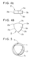
- FIGS 4a and 4b schematically show the valve according to the invention, in front view and in top view respectively.
- Figure 5 schematically shows a cross section through the valve fitted with the valve of Figures 4a and 4b.
- Figures 6a and 6b schematically show a variant of the valve Figures 4a and 4b, in front view and in top view respectively.
- FIG. 3 illustrates an electrochemical generator equipped with a shut-off valve security 20 according to one embodiment of the invention.
- the generator electrochemical is of a conventional type. This is for example a generator nickel-cadmium type electrochemical cell in C or Cs format. He understands a waterproof case 15 in the form of a cylindrical tank of revolution which contains the electrolyte and the electrodes 16 generally produced in spiral form, that is to say in the form of ribbons wrapped around a mandrel. Box 1 is closed from sealed by a cover of the type of the prior art described in relation to the figure 1. For this reason, the cover is here also designated by the number of reference 2 as for that of FIG. 1. The general shape of the cover 2 is that of a disc.
- the safety valve 20 is similar to valve 1 of the prior art described in relationship with Figure 1 insofar as it includes a cup of the same type, arranged identically on cover 2. For this reason, the cup as well as its different parts are identified here by the same numbers of reference as in Figure 1.
- the valve 20 includes a valve 21 which replaces the valve 8 of the prior art detailed in FIG. 2.
- the valve 21 will be described in more detail detail below.
- the cover 2 can advantageously have a form of bowl around the flat area receiving the cup 3 in order to position it when of its mounting on the cover 2 to center it relative to its orifice 6.
- the cup 3 can serve as a current output terminal.
- the electrodes 16 are electrically connected to a blade 17 for example using thin metal strips or any other suitable means.
- Blade 17 presses resiliently against the inner surface of cover 2 to make contact electric with this one.
- the cover 2 is in turn in electrical contact with the cup 3.
- these parts may be made of nickel-plated steel or nickel. If it is an electrode negative, they may be made of nickel or nickel-plated steel.
- the gasket 19 will also provide the electrical insulation required between the cup 3 and the cover 2 on the one hand and the housing 15 on the other hand.
- the cup 3 may be produced by stamping.
- the vent holes 7a and 7b are preferably made simultaneously with the stamping.
- the form of cover bowl 2 can also be obtained by stamping from a flat disc.
- the cup 3 can be fixed on the cover 2 by spot welding or with a weld bead. A person skilled in the art will understand that he is not necessary to ensure a seal between the periphery of the lower end of the dish 3 and cover 2.
- the valve 21 has the shape of a solid bar section whose length is delimited by two planes which are preferably parallel to each other.
- the section of the valve 21 has three vertices - referenced here 22a, 22b, 22c - arranged in triangle, linked together by a respective arc which therefore each corresponds to a respective flank - referenced here 23a, 23b, 23c - of the valve 21.
- the curvature of the arcs is oriented towards the outside; in other words, the flanks 23a, 23b, 23c appear bulging.
- the three vertices 22a, 22b, 22c are preferably arranged in a equilateral triangle.
- the radius of curvature of the arcs of a circle connecting two by two the three vertices 22a, 22b, 22c in an equilateral configuration which is preferred - that is to say the radius of curvature of the sides 23a, 23b, 23b - is greater than the length on one side of the imaginary triangle formed by these three vertices, divided by the root of three.
- the valve 21 therefore has two flat faces 24a, 24b parallel to one another. the other.
- the three sides 23a, 23b, 23c of the valve 21 are preferably all three perpendicular to the same plane. In fact, the three flanks 23a, 23b, 23c may advantageously be perpendicular to the two faces 24a, 24b.
- the valve 21 is made of an elastic material such as an elastomer. At rest - when not assembled and free from external constraints -, the height of the valve 21, i.e. the distance between the two faces 24a and 24b - is more important that the distance between the bottom 5 of the cup 3 of the cover 2. At rest, the diameter circumscribed in the section of the valve 21 is preferably equal to the inside diameter of the tube section 4 of the cup 3.
- the valve 21 is placed inside the cup 3 with the face 24a plated against the bottom 5 of the cup 3 and the other face 24b pressed against the cover 2. It as a result, the valve 21 is compressed between its two faces 24a and 24b. In normal operating condition of the electrochemical generator, the face 24b of the valve 21 is pressed elastically against the cover 2 around the orifice 6 of the compression of the valve 21 between the bottom 5 of the cup 3 and the cover 2. Consequently, the valve 21 seals the orifice 6 of the cover 2 in a leaktight manner.
- the pressure inside the electrochemical generator housing exceeds one given threshold, it further compresses the valve 21 against the bottom 5 at the point of allow the gases to make their way between the face 24b and the cover 2 and reach the free area defined between the sides 23a, 23b, 23c of the valve 21 and the tube section 4, from which the gases escape freely through the vent holes 7a and 7b to the environment outside the electrochemical generator.
- the valve 21 is again tightly applied to the cover 2 around the orifice 6. In Consequently, the orifice 6 is again closed.
- the vertices of the valve section 21 can be rounded instead of pointed. In in this case, it is the diameter circumscribed in the section of the valve 21 taken at the level of the rounded vertices which is preferably equal to the inside diameter of the section of tube 4 of the cup 3.
- the diameter circumscribed in the section of the valve 21 can also be slightly smaller than the inside diameter of the cup 3. It can thus be chosen so that, once compressed between the bottom 5 of the cup 3 and the cover 2, the circumscribed diameter of the section of the valve 21 corresponds to the inside diameter of the cup 3.
- the calibration pressure at which the valve 21 opens depends in particular on the elasticity of the elastomer used and on the compression ratio of the valve 21 in the cup, i.e. the ratio between the height of the valve 21 measured at rest and the distance between the bottom 5 of the cup 3 and cover 2.
- the setting pressure will also depend on the diameter of the orifice 6 and dimensions of the valve section 21.
- the material of the valve 21 is chosen in consideration of its elasticity which allows the valve to be kept tight on port 6 up to the desired gas pressure and its ability to provide sealing around orifice 6 while being resistant to the chemical agents contained in the electrochemical generator. It can advantageously be used a elastomer such as EPDM (Ethylene Propylene-Diene Monomer).
- valve 21 is advantageous in several respects. It allows a precise centering of the valve 21 inside the cup 3. Consequently, the valve 21 is also precisely centered relative to the orifice 6 of the cover 2. The centering of the valve 21 relative to the orifice 6 is therefore improved by compared to the valve 8 of the prior art presented with FIGS. 1, 2a and 2b. By way as a result, there is significantly less dispersion of the set pressure at which opens the valve 21, due to a possible shift of the latter by compared to the orifice 6, unlike the prior art.
- the valve 21 simultaneously closes the two vent holes 7a, 7b. Indeed, if a summit of the section of the valve 21 is positioned at one of the two vent holes 7a, 7b by closing it, the other vent hole necessarily faces the opposite side of the section of the valve 21, which side is necessarily distant from this vent hole. In other words, there is always a sufficient passage for the gases towards one of the two vent holes 7a, 7b between the tube section 4 of the cup 3 and the sides of the valve 21.
- the sides 23a, 23b, 23c can advantageously be rights unlike the valve 8 of the prior art shown in Figures 1, 2a and 2b. Indeed, in the latter case, if the valve 8 is modified so as to have the sides rights over its entire height with a diameter corresponding to that of its part 9, it risk of blocking the two vent holes 7a, 7b during operation of the valve.
- the valve 21 can be produced by punching in an elastomer plate - possibly rectified - whose thickness corresponds to the height of the valve 21.
- This manufacturing method is obviously not applicable to valve 8 of the art anterior due to its frustoconical parts 10a, 10b.
- This method of manufacturing has the advantage of providing valves 21 all having a constant height and precise, unlike the injection / compression process with a mold multi-cavity. Due to the more precise height of the valve 21, the dispersion of the set pressure at which the valve 21 opens is lower from one valve to another in comparison with the valve 8 of the prior art. In addition, productivity is better and the cost price is lower in comparison.
- the valve 21 can be obtained by cutting off an elastomer bar having a cross section of the shape of the section of the valve 21 which will have been obtained by extrusion. This method cannot also not be used to manufacture the valve 8 of the prior art.
- the sides 23a, 23b, 23c each curved in an arc advantage of allowing more reliable automated valve distribution when valve assembly. Indeed, the valve 21 having this section does not risk no jamming in the rails and / or the vibrating distribution bowls fitted to the automated valve assembly machines. From this point of view, in the equilateral configuration which is preferred, it is preferable that the radius of curvature sides 23a, 23b, 23c is less than or equal to twice the length of one side of the imaginary triangle formed by these three vertices 22a, 22b, 22c.
- the radius of curvature of the sides 23a, 23b, 23c is equal to the length of one side of the imaginary triangle formed by these three vertices 22a, 22b, 22c: in this case, the section of the valve 21 is in the shape of a REULEAU triangle.
- This configuration is that shown in Figures 4a and 4b.
- the section of the valve will be all the more advantageous as it approaches the shape of the REULEAU triangle.
- the property of the REULEAU triangle is to have a constant apparent diameter. By apparent diameter, we must understand the distance from any vertex of the REULEAU triangle, respectively 22a, 22b, 22c, to any point on the flank opposite it, respectively 23a, 23b, 23c.
- the REULEAU triangle section valve behaves advantageously like a disc in the vibrating rails and bowls for the distribution of automated assembly machines.
- the apparent diameter of the REULEAU triangle is chosen equal to the diameter of part 9 of valve 8 of art the same distribution rails and bowls may be used to distribute the valves 21 according to the invention.
- the valve 21 will be better centered in the cup 3 in comparison with the valve 8 of the prior art since the diameter circumscribed to the triangle of REULEAU is more important than its diameter apparent.
- the space between the sides 23a, 23b, 23c and the tube section 4 of the cup 3 remains large enough to allow effective degassing through the vent holes 7a and 7b. This situation is illustrated in Figure 5 which represents a cross section through the tube section 4 of the cup 3 with the REULEAU triangle-shaped valve 21 mounted therein.
- the cup 3 made of steel stamped with a thickness of 1 mm, has an internal diameter of 10 mm and the distance from the bottom 5 to the cover 2 is 2 mm.
- the vent holes 7a and 7b have each a diameter of 1 mm.
- the cover 2 made of 0.8 mm thick steel has a hole 6 with a diameter of 2 mm.
- the valve 21, made of EPDM, with a shaped section triangle of REULEAU, has a circumscribed diameter of 9 mm and a thickness 2.5 mm measured at rest, free from external constraints. The resulting valve opens for a pressure of the order of 20 bars.
- the valve 21 is composed of two or several layers of different materials.
- the valve of Figures 4a and 4b has been represented in FIGS. 6a and 6b according to an embodiment with two layers of different materials.
- the lower layer 25a on the side of the face 26a is produced in a first material while the layer 25b on the side of the face 26b is produced in a second material. Since it is the face 26b which closes the orifice 6 of the cover 2, the first material can be defined to resist chemical agents contained in the electrochemical generator and provide a good seal, this regardless of its elasticity.
- the second material is chosen in consideration of its elasticity in order to define the opening pressure of the valve, without having to take into account its ability to provide a seal.
- the valve 21 can also be manufactured by punching in a plate whose thickness corresponds to the height of the valve 21, the plate being obtained by bonding two plates each having the thickness corresponding to layer 25a or 25b and produced in the corresponding material.
- the valve 21 may include a bottom layer, a layer middle and top layer.
- the lower layers and upper are made with the first aforementioned material while the layer intermediate is made with the aforementioned second material, these materials fulfilling the same functions as in the two-layer valve version.
- This three-layer version has the advantage of allowing the valve 21 to be mounted in the valve regardless of its upside down orientation since each of the lower and upper layers is suitable for closing the orifice 6.
- An advantage of the present invention is also to allow the realization of valves 21 having a significant height with respect to its diameter circumscribed. Indeed, the vertices of its section ensure a maintenance in position effective of the valve 21 inside the tube section 4 of the cup 3 over its entire height. This avoids the risk of the valve buckling along its height at inside the cup 3, unlike the valve 8 of the prior art.
- the buckling has the disadvantage of modifying the set pressure at which the valve opens.
- the valve 21 compressed between the bottom 5 of the cup 3 and the cover 2 can thus have a height greater than or equal to once, twice or three times its circumscribed diameter measured at rest. Therefore, it is permissible to define pressures opening of the valve in pressure ranges and applications in which valves 8 of the prior art are not applicable.
- the present invention is not limited to the embodiment described and represented, but it is susceptible of numerous variants accessible to one skilled in the art.
- the section of the valve can also be adapted so that the vertices are each connected by an arc of a circle going towards the center of the section.
- the valve according to the invention can be arranged directly on the casing of the electrochemical generator instead of being arranged on its cover.
- the vent holes in the cup may not be diametrically opposed by relative to the cup, but have any angular deviation which does not correspond not at the angular distance between the different vertices of the valve section.
- the valve cup may include more than two vent holes. The holes can be arranged at a different level on the tube section 4 instead to be adjacent to the bottom 5.
- the vent holes may be formed of grooves extending over all or part of the height of the tube section 4 from the cover 2 at the bottom 5, or even even extending at the bottom 5.
- the cup 3 can also have an ellipsoidal section instead of being strictly circular.
- the section of the valve could possibly be adapted, for example in such a way that the vertices are arranged in a triangle isosceles so that each of the vertices touches the interior wall of the section of tube 4 or that these vertices are equidistant from this wall: it follows that the valve is oriented inside the cup.
- the valve according to the invention can be applied more generally to any pressure housing other than those of electrochemical generators.
Landscapes
- Engineering & Computer Science (AREA)
- General Engineering & Computer Science (AREA)
- Chemical & Material Sciences (AREA)
- Chemical Kinetics & Catalysis (AREA)
- Electrochemistry (AREA)
- General Chemical & Material Sciences (AREA)
- Mechanical Engineering (AREA)
- Gas Exhaust Devices For Batteries (AREA)
Abstract
Description
Claims (24)
- Soupape comprenant un clapet élastique (21) comprimé par une première paroi (5) contre un orifice (6) d'une deuxième paroi (2) et entouré par une troisième paroi (4), caractérisée en ce que le clapet a une section, suivant un plan parallèle à la première paroi (5) ou à la deuxième paroi (2), présentant trois sommets (22a, 22b, 22c) disposés en triangle, les trois sommets (22a, 22b, 22c) de ladite section du clapet étant reliés deux à deux par un arc de cercle respectif.
- Soupape selon la revendication 1, dans laquelle chacun des arcs de cercle est situé à l'extérieur du triangle imaginaire défini par les trois sommets.
- Soupape selon la revendication 2, dans laquelle le rayon de courbure de chacun des arcs de cercle est inférieur ou égal à deux fois la longueur d'un côté du triangle imaginaire formé par les trois sommets.
- Soupape selon l'une des revendications 2 et 3, dans laquelle le rayon de courbure de chacun des arcs de cercle est supérieur ou égal à : R ≥ L x (3 + √3) / 6 avec R le rayon de courbure de l'arc de cercle et L la longueur d'un côté du triangle imaginaire formé par les trois sommets.
- Soupape selon l'une des revendications 2 à 4, dans laquelle le rayon de courbure de chacun des arcs de cercle est égal à la longueur d'un côté du triangle imaginaire formé par les trois sommets.
- Soupape selon l'une des revendications précédentes, dans laquelle la troisième paroi (4) a une section circulaire.
- Soupape selon la revendication 6, caractérisée en ce que le diamètre circonscrit aux trois sommets de ladite section du clapet, mesuré libre de toutes contraintes extérieures, est supérieur ou égal à 0,8 fois le diamètre intérieur de la troisième paroi.
- Soupape selon la revendication 7, dans laquelle le diamètre circonscrit aux trois sommets de ladite section du clapet, mesuré libre de toutes contraintes extérieures, est supérieur ou égal à 0,9 fois le diamètre intérieur de la troisième paroi.
- Soupape selon la revendication 8, dans laquelle le diamètre circonscrit aux trois sommets de la section triangulaire du clapet, mesuré libre de toutes contraintes extérieures, est égal au diamètre intérieur de la troisième paroi.
- Soupape selon l'une des revendications précédentes, dans laquelle la première paroi est parallèle à la deuxième paroi.
- Soupape selon l'une des revendications précédentes, dans laquelle les deux faces du clapet venant en contact avec respectivement la première paroi et la deuxième paroi, sont parallèles.
- Soupape selon l'une des revendications précédentes, dans laquelle les flancs du clapet définissant ladite section sont tous perpendiculaires à un même plan.
- Soupape selon l'une des revendications 10 à 12, caractérisée en ce que les flancs du clapet définissant ladite section, sont tous perpendiculaires aux deux faces du clapet en contact avec respectivement la première paroi et la deuxième paroi.
- Soupape selon l'une des revendications précédentes, dans laquelle les sommets de ladite section du clapet sont disposés suivant un triangle équilatéral.
- Soupape selon l'une des revendications précédentes, dans laquelle l'orifice de la deuxième paroi est centré sur l'axe de la troisième paroi.
- Soupape selon l'une des revendications précédentes, dans laquelle au moins une ouverture d'évent (7a, 7b) est agencée dans la troisième paroi ou dans la première paroi.
- Soupape selon la revendication 16, comprenant deux ouvertures d'évent agencées dans la troisième paroi ou dans la première paroi et qui sont diamétralement opposées par rapport à l'axe de la troisième paroi.
- Soupape selon l'une des revendications précédentes, dans laquelle la distance entre la première paroi et la deuxième paroi est supérieure ou égale à une fois le diamètre circonscrit aux trois sommets de ladite section du clapet, mesuré libre de toutes contraintes extérieures.
- Soupape selon la revendication 18, dans laquelle la distance entre la première paroi et la deuxième paroi est supérieure ou égale à deux fois le diamètre circonscrit aux trois sommets de ladite section du clapet, mesuré libre de toutes contraintes extérieures.
- Soupape selon la revendication 19, dans laquelle la distance entre la première paroi et la deuxième paroi est supérieure ou égale à trois fois le diamètre circonscrit aux trois sommets de ladite section du clapet, mesuré libre de toutes contraintes extérieures.
- Soupape selon l'une des revendications précédentes, dans laquelle le clapet comprend plusieurs couches de matériaux superposées.
- Générateur électrochimique comprenant une soupape selon l'une des revendications précédentes.
- Générateur électrochimique selon la revendication 22, caractérisé en ce que la deuxième paroi fait partie d'un couvercle fermant le générateur électrochimique.
- Générateur électrochimique selon l'une des revendications 22 et 23, caractérisé en ce que la deuxième paroi ou la troisième paroi constitue une borne de sortie de courant.
Applications Claiming Priority (2)
| Application Number | Priority Date | Filing Date | Title |
|---|---|---|---|
| FR0100077A FR2819036B1 (fr) | 2001-01-04 | 2001-01-04 | Soupape et generateur electrochimique comprenant une telle soupape |
| FR0100077 | 2001-01-04 |
Publications (2)
| Publication Number | Publication Date |
|---|---|
| EP1221728A1 true EP1221728A1 (fr) | 2002-07-10 |
| EP1221728B1 EP1221728B1 (fr) | 2016-01-20 |
Family
ID=8858515
Family Applications (1)
| Application Number | Title | Priority Date | Filing Date |
|---|---|---|---|
| EP01402994.6A Expired - Lifetime EP1221728B1 (fr) | 2001-01-04 | 2001-11-22 | Soupape refermable et générateur électrochimique comprenant une telle soupape |
Country Status (3)
| Country | Link |
|---|---|
| US (1) | US6713208B2 (fr) |
| EP (1) | EP1221728B1 (fr) |
| FR (1) | FR2819036B1 (fr) |
Families Citing this family (19)
| Publication number | Priority date | Publication date | Assignee | Title |
|---|---|---|---|---|
| JP4232038B2 (ja) * | 2004-08-11 | 2009-03-04 | 日本電気株式会社 | フィルム外装電気デバイスおよびその製造方法 |
| US7839703B2 (en) * | 2007-06-15 | 2010-11-23 | Micron Technology, Inc. | Subtraction circuits and digital-to-analog converters for semiconductor devices |
| DE102008002665A1 (de) * | 2008-06-26 | 2009-12-31 | Robert Bosch Gmbh | Batteriepack und Handwerkzeugmaschine mit einem Batteriepack |
| US9140501B2 (en) | 2008-06-30 | 2015-09-22 | Lg Chem, Ltd. | Battery module having a rubber cooling manifold |
| US9605914B2 (en) | 2012-03-29 | 2017-03-28 | Lg Chem, Ltd. | Battery system and method of assembling the battery system |
| US9105950B2 (en) | 2012-03-29 | 2015-08-11 | Lg Chem, Ltd. | Battery system having an evaporative cooling member with a plate portion and a method for cooling the battery system |
| US9379420B2 (en) | 2012-03-29 | 2016-06-28 | Lg Chem, Ltd. | Battery system and method for cooling the battery system |
| US9306199B2 (en) | 2012-08-16 | 2016-04-05 | Lg Chem, Ltd. | Battery module and method for assembling the battery module |
| US9960395B2 (en) * | 2012-08-16 | 2018-05-01 | Lg Chem, Ltd. | Battery module |
| US9083066B2 (en) | 2012-11-27 | 2015-07-14 | Lg Chem, Ltd. | Battery system and method for cooling a battery cell assembly |
| US9184424B2 (en) | 2013-07-08 | 2015-11-10 | Lg Chem, Ltd. | Battery assembly |
| US10770762B2 (en) | 2014-05-09 | 2020-09-08 | Lg Chem, Ltd. | Battery module and method of assembling the battery module |
| US10084218B2 (en) | 2014-05-09 | 2018-09-25 | Lg Chem, Ltd. | Battery pack and method of assembling the battery pack |
| US9627724B2 (en) | 2014-12-04 | 2017-04-18 | Lg Chem, Ltd. | Battery pack having a cooling plate assembly |
| US9960465B2 (en) | 2015-07-30 | 2018-05-01 | Lg Chem, Ltd. | Battery pack |
| US9755198B2 (en) | 2015-10-07 | 2017-09-05 | Lg Chem, Ltd. | Battery cell assembly |
| KR102689778B1 (ko) * | 2021-06-30 | 2024-07-31 | 삼성에스디아이 주식회사 | 이차전지 |
| CN116443587A (zh) * | 2023-05-31 | 2023-07-18 | 国能龙源环保有限公司 | 翻板阀及气力输灰设备 |
| CN118380718B (zh) * | 2024-06-21 | 2024-08-23 | 蜂巢能源科技股份有限公司 | 一种单体电池 |
Citations (6)
| Publication number | Priority date | Publication date | Assignee | Title |
|---|---|---|---|---|
| US3484301A (en) * | 1966-01-03 | 1969-12-16 | Texas Instruments Inc | Electrical cell vent valve |
| US3715239A (en) * | 1971-04-05 | 1973-02-06 | Gates Rubber Co | Electrochemical cell closure and method of making |
| US3994749A (en) * | 1975-08-21 | 1976-11-30 | Motorola, Inc. | Vent valve for nickel-cadmium energy cells |
| US4662533A (en) * | 1984-01-19 | 1987-05-05 | Matsushita Electric Industrial Co., Ltd. | Safety valve device for enclosed cells |
| US4993602A (en) * | 1989-06-07 | 1991-02-19 | Prd, Inc. | Pressure relief device for a pressurized container |
| JPH05190164A (ja) * | 1992-01-14 | 1993-07-30 | Hitachi Maxell Ltd | 密閉形アルカリ蓄電池 |
-
2001
- 2001-01-04 FR FR0100077A patent/FR2819036B1/fr not_active Expired - Fee Related
- 2001-11-22 EP EP01402994.6A patent/EP1221728B1/fr not_active Expired - Lifetime
- 2001-12-20 US US10/022,894 patent/US6713208B2/en not_active Expired - Lifetime
Patent Citations (6)
| Publication number | Priority date | Publication date | Assignee | Title |
|---|---|---|---|---|
| US3484301A (en) * | 1966-01-03 | 1969-12-16 | Texas Instruments Inc | Electrical cell vent valve |
| US3715239A (en) * | 1971-04-05 | 1973-02-06 | Gates Rubber Co | Electrochemical cell closure and method of making |
| US3994749A (en) * | 1975-08-21 | 1976-11-30 | Motorola, Inc. | Vent valve for nickel-cadmium energy cells |
| US4662533A (en) * | 1984-01-19 | 1987-05-05 | Matsushita Electric Industrial Co., Ltd. | Safety valve device for enclosed cells |
| US4993602A (en) * | 1989-06-07 | 1991-02-19 | Prd, Inc. | Pressure relief device for a pressurized container |
| JPH05190164A (ja) * | 1992-01-14 | 1993-07-30 | Hitachi Maxell Ltd | 密閉形アルカリ蓄電池 |
Non-Patent Citations (1)
| Title |
|---|
| PATENT ABSTRACTS OF JAPAN vol. 017, no. 608 (E - 1457) 9 November 1993 (1993-11-09) * |
Also Published As
| Publication number | Publication date |
|---|---|
| US6713208B2 (en) | 2004-03-30 |
| FR2819036B1 (fr) | 2004-01-16 |
| US20020086201A1 (en) | 2002-07-04 |
| FR2819036A1 (fr) | 2002-07-05 |
| EP1221728B1 (fr) | 2016-01-20 |
Similar Documents
| Publication | Publication Date | Title |
|---|---|---|
| EP1221728B1 (fr) | Soupape refermable et générateur électrochimique comprenant une telle soupape | |
| EP2809537B1 (fr) | Boîtier pour module électrique d'un pack batterie pour véhicule automobile et pack batterie associé | |
| EP0948064B1 (fr) | Accumulateur ou pile prismatique avec container rigide et compressif | |
| EP0875949B1 (fr) | Bouchon à soupape pour accumulateur électrique | |
| CA3105863C (fr) | Ensemble event de securite de batterie | |
| EP2828906B1 (fr) | Ensemble de stockage d'énergie comprenant une bague élastique isolante électriquement | |
| FR2835609A1 (fr) | Capteur de temperature a thermistance et son procede de fabrication | |
| EP1336059B1 (fr) | Robinet avec soufflet etanche et presse-etoupe pour recipient de transport de fluides toxiques | |
| LU82759A1 (fr) | Pile electrique etanche | |
| CA2847105C (fr) | Ensemble de stockage d'energie longue duree a piece de connexion intermediaire | |
| EP3727952B1 (fr) | Générateur de gaz pour système de sécurité | |
| CA2863348C (fr) | Couvercle pour ensemble de stockage d'energie, ensemble de stockage d'energie comportant ledit couvercle, et procede de fabrication d'un tel ensemble de stockage d'energie | |
| FR2822215A1 (fr) | Joint de culasse | |
| EP3316350B1 (fr) | Piece de connexion electrique pour accumulateur | |
| EP0149384B1 (fr) | Tube à fond soudé, notamment pour la réalisation d'un ressort à gaz sous forte pression | |
| FR2564247A1 (fr) | Soupape de decharge de gaz pour accumulateur electrique etanche | |
| FR2798227A1 (fr) | Traversee de paroi pour generateur electrochimique etanche | |
| FR3167767A3 (fr) | Ensemble couvercle pour une cellule de batterie prismatique | |
| WO2024236107A1 (fr) | Cellule électrochimique pour batterie électrique | |
| EP0331591A1 (fr) | Capsule électroacoustique à membrane piézoélectrique | |
| CH721380A2 (fr) | Pile, notamment pile bouton, son procédé de fabrication et jeu de piles | |
| FR3161807A1 (fr) | Cellule cylindrique de batterie électrique et couvercle hermétique correspondant. | |
| FR3131096A1 (fr) | Couvercle pour élément électrochimique | |
| FR2748542A1 (fr) | Dispositif pour l'accouplement etanche de deux tubes lisses | |
| EP0557938A1 (fr) | Batterie acide-plomb de type étanche |
Legal Events
| Date | Code | Title | Description |
|---|---|---|---|
| PUAI | Public reference made under article 153(3) epc to a published international application that has entered the european phase |
Free format text: ORIGINAL CODE: 0009012 |
|
| AK | Designated contracting states |
Kind code of ref document: A1 Designated state(s): AT BE CH CY DE DK ES FI FR GB GR IE IT LI LU MC NL PT SE TR |
|
| AX | Request for extension of the european patent |
Free format text: AL;LT;LV;MK;RO;SI |
|
| 17P | Request for examination filed |
Effective date: 20030110 |
|
| AKX | Designation fees paid |
Designated state(s): DE FR GB |
|
| RAP1 | Party data changed (applicant data changed or rights of an application transferred) |
Owner name: SAFT FINANCE S.AE.R.L. |
|
| 17Q | First examination report despatched |
Effective date: 20070726 |
|
| RAP1 | Party data changed (applicant data changed or rights of an application transferred) |
Owner name: ARTS ENERGY |
|
| GRAP | Despatch of communication of intention to grant a patent |
Free format text: ORIGINAL CODE: EPIDOSNIGR1 |
|
| INTG | Intention to grant announced |
Effective date: 20150617 |
|
| GRAS | Grant fee paid |
Free format text: ORIGINAL CODE: EPIDOSNIGR3 |
|
| GRAA | (expected) grant |
Free format text: ORIGINAL CODE: 0009210 |
|
| AK | Designated contracting states |
Kind code of ref document: B1 Designated state(s): DE FR GB |
|
| REG | Reference to a national code |
Ref country code: GB Ref legal event code: FG4D Free format text: NOT ENGLISH |
|
| REG | Reference to a national code |
Ref country code: DE Ref legal event code: R096 Ref document number: 60149744 Country of ref document: DE |
|
| REG | Reference to a national code |
Ref country code: DE Ref legal event code: R097 Ref document number: 60149744 Country of ref document: DE |
|
| PLBE | No opposition filed within time limit |
Free format text: ORIGINAL CODE: 0009261 |
|
| STAA | Information on the status of an ep patent application or granted ep patent |
Free format text: STATUS: NO OPPOSITION FILED WITHIN TIME LIMIT |
|
| 26N | No opposition filed |
Effective date: 20161021 |
|
| REG | Reference to a national code |
Ref country code: DE Ref legal event code: R119 Ref document number: 60149744 Country of ref document: DE |
|
| GBPC | Gb: european patent ceased through non-payment of renewal fee |
Effective date: 20161122 |
|
| REG | Reference to a national code |
Ref country code: FR Ref legal event code: ST Effective date: 20170731 |
|
| PG25 | Lapsed in a contracting state [announced via postgrant information from national office to epo] |
Ref country code: FR Free format text: LAPSE BECAUSE OF NON-PAYMENT OF DUE FEES Effective date: 20161130 |
|
| PG25 | Lapsed in a contracting state [announced via postgrant information from national office to epo] |
Ref country code: DE Free format text: LAPSE BECAUSE OF NON-PAYMENT OF DUE FEES Effective date: 20170601 Ref country code: GB Free format text: LAPSE BECAUSE OF NON-PAYMENT OF DUE FEES Effective date: 20161122 |