BACKGROUND OF THE INVENTION
Field of the Invention
-
This invention relates to an electrical switching apparatus and, more
specifically, to an electrical switching apparatus having a magnetic blow-open device.
Background Information
-
Electrical switching apparatus for power distribution systems includes devices
such as, but not limited to, circuit breakers, network protectors and transfer switches.
Circuit breakers include both power circuit breakers and current limiting circuit
breakers. A power circuit breaker is typically disposed upstream of other circuit
breakers and is structured to delay its tripping action allow a limited fault current to
pass therethrough. This allows the downstream circuit breaker closer to the fault to
trip. If the fault current is not interrupted by a downstream circuit breaker, the power
circuit breaker will trip. Power circuit breakers, however, are unable to withstand
very high, e.g. greater than 150 kA, fault currents. For such higher ratings, a current
limiting circuit breaker is used. A current limiting circuit breaker is structured to
open within a few milliseconds after experiencing a very high fault current, thus
limiting the fault current to a value much less than the available prospective peak
value.
-
One type of current limiting circuit breaker is a "fused" current limiting circuit
breaker. A fused current limiting circuit breaker uses the current limiting action of
series connected current limiting fusses to achieve the required rapid response. This
allows the circuit breaker to open at a slower rate, i.e. similar to a power circuit
breaker. It would be desirable to have a "fuseless" current limiting circuit breaker.
-
A common type of power air circuit breaker has a molded casing housing and
multiple pole assemblies all driven by a common operating mechanism through a
rotatable pole shaft. Each pole includes a contact arm carrier pivoted by a pole arm on
the pole shaft between closed and open positions. The contact arm carriers support
contact arms having movable contacts which engage stationary contacts with the
contact arm carrier in the closed position. Typically, the contact arm is made up of a
number of contact arm laminations or fingers mounted on a common pivot pin on the
carrier. Contact springs bias the contact fingers against the stationary contacts in the
closed position to provide contact pressure and to accommodate for wear. As the
movable contact carrier is closed, typically by a spring operated closing and/or reset
mechanism, the contact springs are compressed.
-
Typically, the switching apparatus is structured so that all of the movable
contacts are held against the stationary contact by a mechanical force. The
mechanical force is sufficient to overcome the electromagnetic force created by
current flowing through the contacts and the force of the compressed contact springs.
To open the circuit breaker, the mechanical force is released and the all of the contacts
are separated. Separation of the contacts is caused by the contact springs expanding.
As the contact springs expand, the movable contact carrier is moved away from the
stationary contact. By the time the contact springs are fully expanded, the movable
contact carrier has enough momentum to pull the contact arm fingers away from the
stationary contact. When a large over-current is present, the separation of the contacts
is also aided by the electromagnetic repulsion force between the stationary and
movable contacts.
-
The prior art release mechanism included a rotatable pole shaft having a lobe
that was coupled by a link assembly to the movable contact carrier. The link
assembly included a rigid link member disposed between the pole shaft and the
contact carrier. The combination of the pole shaft and the link assembly created the
mechanical force that held the movable contact carrier in place. The release
mechanism was structured so that the pole shaft rotated causing the lobe to move
away from the stationary contact. As the lobe moved away from the stationary
contact, the mechanical force was released and the contact springs moved the
movable contact away from the stationary contact. The link assembly was rotatably
attached to both the pole shaft and the movable contact. Thus, movement of the
contact carrier was always associated with the rotation of the pole shaft. The link
assembly was not structured to have a knee joint or otherwise be flexible.
-
From the perspective of a current limiting circuit breaker, the prior art release
mechanism has several disadvantages. First, the release mechanism was generally
structured to release all poles of the switching apparatus at one time. Second, the
release mechanism did not respond rapidly to an over-current position. Additionally,
power circuit breakers can not be easily converted into current limiting circuit
breakers
-
There is a need, therefore, for a release mechanism that allows for each pole of
a multi-pole switching apparatus to separate as soon as an over-current condition
occurs in that pole.
-
There is a further need for a release mechanism having a rapid response time.
-
There is a further need for a release mechanism that can be integrated with
existing switching apparatus.
There is a further need for a release mechanism that can be incorporated into a power
circuit breaker to convert the power circuit breaker into a current limiting circuit
breaker.
SUMMARY OF THE INVENTION
-
This need and others are satisfied by the invention which is directed to
electrical switching apparatus in which an electromagnetic blow-open device is
incorporated into the assembly connecting the pole shaft to the movable contact.
-
The electromagnetic blow-open device includes a link assembly having a first
link member and a second link assembly which are rotatably coupled to each other at
a knee joint. The electromagnetic blow-open device also includes an actuating arm
coupled to the fist and second link assemblies at the knee joint. The rotation of the
first and second link assemblies relative to each other is limited by a stop means.
Thus, when assembled, the first and second link assemblies may not rotate past a
certain point. When the switching device is closed, or reset, the first and second links
are brought to the point where no more rotation is possible. This is the over-toggle
position of the link assembly. The link assembly is held in the over-toggle position by
the force biasing the movable contact away from the stationary contact. This force
includes both the electromagnetic repulsion force between the contacts, when current
is flowing, and the force of the contact springs on the movable contact carrier.
-
The actuating arm includes a flapper assembly. The flapper assembly is,
generally, a flat member of ferromagnetic material which extends adjacent to the
contact arm fingers on the movable contact carrier. As a current passes through the
contact arm fingers a magnetic field is created. The magnetic field attracts the flapper
assembly. Under normal operating conditions, the magnetic field is not strong enough
to overcome the force of the contact springs holding the link assembly in the over-toggle
position. When an over-current condition occurs, the strength of the magnetic
field increases and draws the flapper assembly towards the contact arm fingers. As
the flapper is drawn toward the contact arm fingers, the actuating arm acts on the knee
joint causing the first and second links to move back through the toggle position.
Once the first and second links are out of the over-toggle position, the linkage will
collapse and the movable contact carrier is free to move away from the stationary
contact. Separation of the contacts is assisted by the force of the contact springs
expanding and the magnetic field generated by the fault current.
-
Thus, when the link assembly moves out of the over-toggle position, the
contact carrier moves away from the stationary contact without the pole shaft rotating.
The time-current characteristics of the trip unit are coordinated with the tripping
action of the blow-open device, so that, when a pole opens, the release mechanism for
the remaining poles is actuated. Opening the circuit breaker with the poleshaft also
acts to reset the blow-open device by moving the link assembly back into the over-toggle
position. Resetting the release mechanism will maintain the link assembly in
the over-toggle position even when the blow-open device has not been activated, e.g.,
after the circuit breaker is manually opened.
-
Using this electromagnetic blow-open device allows one to change a power
circuit breaker into a current limiting circuit breaker simply by installing the
electromagnetic blow-open device in place of the prior art link assembly.
BRIEF DESCRIPTION OF THE DRAWINGS
-
A full understanding of the invention can be gained from the following
description of the preferred embodiments when read in conjunction with the
accompanying drawings in which:
- Figure 1 is an exploded isometric view of a power air circuit breaker
incorporating the invention.
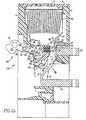
- Figure 2a is a vertical section through the circuit breaker of Figure 1 shown in
the fully closed position.
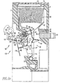
- Figure 2b is similar to Figure 2a but illustrating the electromagnetic blow-open
device in the collapsed position.
- Figure 2c is similar to Figure 2a but illustrating the electromagnetic blow-open
device in the reset position.
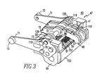
- Figure 3 is an isometric view of the contact carrier which forms part of the
circuit breaker with some parts eliminated for clarity.
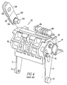
- Figure 4 is an isometric view of the prior art drive link assembly engaging the
carrier.
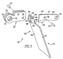
- Figure 5 is an exploded, isometric view of the electromagnetic blow-open
device.
- Figure 6 is an isometric view of the electromagnetic blow-open device.
- Figure 7 is an isometric view of a partial view of a circuit breaker pole with
the electromagnetic blow-open device in the closed position.
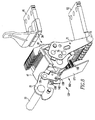
- Figure 8 is an isometric view of a partial view of a circuit breaker pole with
the electromagnetic blow-open device in the tripped position.
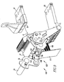
- Figure 9 is an isometric view of a partial view of a circuit breaker pole with
the electromagnetic blow-open device in the reset position.
- Figure 10 is an exploded isometric view of an alternate electromagnetic blow-open
device.
- Figure 11 is an isometric view of the alternate electromagnetic blow-open
device of Figure 10.
- Figure 12 is an isometric, partial view of a circuit breaker pole with the
electromagnetic blow-open device in the closed position.
- Figure 13 is an isometric, partial view of a circuit breaker pole with the
electromagnetic blow-open device in the tripped position.
- Figure 14 is an isometric view of a partial view of a circuit breaker pole with
the electromagnetic blow-open device in the reset position.
- Figure 15 is an exploded view of the electromagnetic blow-open device with
an adjustable cam on the over-toggle stop pin.
-
DETAILED DESCRIPTION OF THE PREFERRED EMBODIMENT
-
The invention is applicable to electrical switching apparatus such as, for
example, circuit breakers, network protectors, transfer switches and disconnect
switches, and will be described as applied to a power circuit breaker. The circuit
breaker depicted is similar to the circuit breaker shown in U.S. Patent No. 6,066,821,
which is incorporated by reference.
-
Referring to Figure 1, the power air circuit breaker 1 incorporating the
invention has a housing 3 which includes a molded front casing 5 and rear casing 7,
and a cover 9. The exemplary circuit breaker 1 has three poles 10 with the front and
rear casings 5, 7 forming three pole chambers 11. Each pole 10 also has an arc
chamber 13 which is enclosed by a ventilated arc chamber cover 15.
-
The circuit breaker 1 has an operating mechanism 17 which is mounted on the
front of the front housing 5 and is enclosed by the cover 9. The operating mechanism
17 has a front face 19 which is accessible through an opening 21 in the cover. The
operating mechanism 17 includes a large spring 18 which is charged to store energy
for closing the circuit breaker. The face plate 19 mounts a push to close button 23
which is actuated to discharge the close spring for closing the circuit breaker and a
push to open button 25 for opening the circuit breaker. Indicators 27 and 29 display
the condition of the charge spring and the open/close state of the contacts,
respectively. The charge spring is charged by operation of the charging handle 31 or
remotely by a motor operator (not shown).
-
The common operating mechanism 17 is connected to the individual poles by
a pole shaft 33 having a lobe 35 for each pole. As is conventional, the operating
mechanism 17 includes a trip unit (not shown) which actuates the operating
mechanism to open all the poles of the circuit breaker through rotation of the pole
shaft 33 in response to predetermined characteristics of the current flowing through
the circuit breaker.
-
As illustrated in Figures. 2a-2c, each pole of the circuit breaker 1 includes
separable main contacts 37 comprising stationary main contacts 39 and movable main
contacts 41. The stationary main contacts 39 are secured to a line conductor 43 which
is mounted in and projects rearwardly from the rear casing 7. The movable main
contacts 41 are mounted on a moving conductor assembly 45. This assembly includes
a contact carrier 47 on which a plurality of contact fingers 49 are pivotally mounted
by a pivot pin 51. The movable main contacts 41 are fixed to the contact fingers 49
about midway between the pivot pin 51 and a first or free end 53. Adjacent to the free
end 53 of the contact fingers is an arc toe 55 forming a movable arcing contact which
cooperates with a toe block 57 forming a stationary arcing contact secured to the line
conductor through an electrically conductive spacer 59 to form a set of arcing
contacts.
-
The moving conductor assembly 45 further includes flexible shunts 61
connecting the contact fingers 49 to a load conductor 63 also projecting rearwardly
from the rear casing 7. As is conventional, an arc chute 65 is provided in the arc
chamber 13. An arc runner 67 guides the arc from the toe block to the arc chamber
where it is extinguished in a known manner.
-
Turning to Figures 3 and 4 in addition to Figures 2a-2c, the contact carrier 47
includes a molded body 69 and a pair of legs 71 secured to the ends of the body 69 by
bolts 70. Mounting pivots 73 project outwardly from the free ends of the legs 71. The
pivot pin 51 is supported at its ends in the legs 71. The contact fingers 49 are pivotally
mounted on the pivot pin 51. Second ends 75 of the contact fingers 49 are biased
against a stop ledge 77 on the molded body 69 by a pair of contact springs 79 seated
in recesses 81 in the molded body. The stop ledge 77 has a contour which includes a
recessed section 83 in the center of the stop ledge. This allows the contact springs 79
to rotate the center contact fingers which are aligned with the recess 83 to project the
first or free ends 53 further from the contact carrier than the other, outside, contact
fingers.
-
As shown in Figure 2c, the contact carrier 47 is pivotally mounted for rotation
to open and close the separable contacts 37. Bearing pockets 113 are formed by
mating recesses 115 in the front casing 5 and rear casing 7 for the pivot 73 on the free
ends of the legs 71. The carrier 47 is rotated about the pivots 73 by a link assembly
120 pivotally connected to the pole lobe 35 on the pole shaft 33.
-
Generally, the operation of the circuit breaker 1 when being opened by the
tripping mechanism is as follows: with the contact carrier 47 rotated to the fully
closed position shown in Figure 2a, the separable contacts 37 are closed to complete a
circuit which includes the line conductor 43, the fixed contacts 39, the movable
contacts 41, the contact arms 49, the flexible shunts 61 and the load conductor 63. In
this fully closed position, the arcing contacts are open. Also, in the fully closed
position the second ends 75 of the contact arms are spaced from the stop ledge 77.
The contact springs 79 maintain contact pressure between the fixed and movable
contacts 39, 41.
-
As the circuit breaker begins to open, the contact carrier 49 begins to rotate
counterclockwise to the position shown in Figure 2b. In this position, with the carrier
slightly spaced counterclockwise from the position in Figure 2a, the contact springs
79 rock the contact fingers 49 clockwise so that they rock about the separable contacts
37 and close the arcing contacts. At this point, current flows both through the closed
separable contacts and arcing contacts. As the contact carrier continues its
counterclockwise rotation during opening and reaches a position where the separable
contacts have separated. In addition, the second ends 75 of the outer contact fingers
have seated on the stop ledge 77 and are therefore rotated with the carrier to open the
associated arcing contacts as well as the separable contacts. However, the second ends
of the center contact fingers 49c enter the recess 83 in the stop ledge 77 and therefore
can continue to rotate and maintain the center arcing contacts closed. Continued
rotation of the carrier 47 in the counterclockwise direction then results in the drawing
of an arc between a toe block 57 and the arc toes 55c on the center contact fingers
only. This arc is then transferred by the arc runner 67 to the arc chute 65 where it is
extinguished.
-
Figure 2c shows the carrier in the fully open position with the center contact
fingers 49c advanced. Thus, as the carrier 47 moves to the closed position during the
next closing cycle, the arcing contacts of the center contact arms will touch first
followed by the arcing contacts of the outer contact fingers. This will cause the
contact fingers to rock to the position shown in Figure 2b where both the arcing
contacts and the separable contacts are closed. As the carrier reaches the fully closed
position of Figure 2a, the arcing contacts separate and all the current flows through
the closed separable contacts 37.
-
The prior art link assembly 320 is shown in Figure 4. The prior art link
assembly included two rigid link members 322, 324 having offset ends 326, 328. The
offset ends 326, 328 straddled the pole lobe 35 and were connected to the pole lobe 35
by a pin. The non-offset ends 332, 334 of rigid link members 322, 324 were coupled
by a drive pin 336 to the carrier 47.
-
As shown in Figure 2a, the electromagnetic blow-open device 120 includes a
collapsible linkage 100 having a first end 101 and a second end. 102. The collapsible
linkage 100 has a rigid position and a changeable position. In the rigid position, the
collapsible linkage 100 has a generally fixed length between the first end 101 and the
second end 102. In the changeable position, the first end 101 and the second end 102
may be drawn together. The collapsible linkage 100 is disposed between, and
coupled to, the pole shaft 33 and contact carrier 47. The electromagnetic blow-open
device 120 further includes an actuator arm 160 coupled to the collapsible linkage
100. The actuator arm 160 is structured to be responsive to a large over-current in the
10 pole. When an over-current condition occurs, the actuator arm 160 shifts the
collapsible linkage 100 from the rigid position to the changeable position. Thus, the
collapsible linkage 100 is structured to maintain the stationary contact 39 and the
movable contact 41 in the closed position while the collapsible linkage 100 is in the
rigid position and to allow the stationary contact 39 and movable contact 41 to move
to the open position when the collapsible linkage 100 is in said changeable position.
Additionally, the main contacts 37 separate without the pole shaft 33 rotating.
-
The embodiment of the electromagnetic blow-open device 120 shown in
Figure 5 includes a plurality of link elements 106. One of the link elements 106
includes and over-toggle stop 108. When an adjacent link contacts the over-toggle
stop 108, the links are in an over-toggle position. When the link elements 106 are in
the over-toggle position, the collapsible linkage 100 is in the rigid position. The
interaction between the link elements 106 and the actuator arm 160 is set forth in
more detail below. There are other types of collapsible linkages available. For
example, the collapsible linkage 100 could be a telescoping member held in place by
a detent. In this configuration, the actuator arm 160 releases the pressure on the
detent and allows the telescoping member to collapse.
-
As shown in Figure 5, the link elements 106 include a first link assembly 130
and a second link assembly 140 which are rotatably coupled to each other at a knee
joint 150 (Figure 6) by a pivot pin 122. The first link assembly 130 includes two rigid
planar members 131, 132. Each rigid planar member 131, 132 has a first end 133 and
a second end 134. Both the first end 133 and the second end have an opening 135,
136, respectively, therein structured to allow a pin to pass through either rigid planar
member 132, 134. The rigid planar members 132, 134 are coupled to, and held in a
spaced, generally parallel relation by, a over-toggle stop pin 137 disposed in the
medial portion of each rigid planar member 132, 134 through a stop pin opening 138.
-
The second link assembly 140 includes a rigid planar member 141. The rigid
planar member 141 has a first end 143 and a second end 144. Both the first end 143
and the second end have an opening 145, 146 therein structured to allow a pin to pass
through either the rigid planar member 142. The planar member second end 144
includes a tab 139 that extend in a direction toward the flapper assembly 170,
described below.
-
The electromagnetic blow-open device 120 also includes a actuator arm 160.
The actuator arm includes an attachment end 161 having a two tabs 162, 163 each
with an opening 164 therethrough. The two tabs 162, 163 are, preferably, spaced to
fit on the outer sides of the first link assembly 130. The tabs 162, 163 are maintained
in a spaced relation by crossbar 168. The actuator arm 160 further includes a shoulder
portion 165 having at least one shoulder 166. The shoulder 166 preferably extend
from crossbar 168 in a direction perpendicular to the longitudinal axis of the tabs 162,
163 so that a portion of the shoulder 166 is not in the same plane as the longitudinal
plane of the tabs 162, 163. The shoulder portion 165 may be integral to a flapper
assembly 170. The flapper assembly 170 is preferably a flat, rigid metallic member
171. However, as described below, the flapper assembly 170 may have many shapes.
-
When assembled, as shown in Figure 6, the electromagnetic blow-open device
120 has actuator arm attachment end 161 disposed with tabs 162, 163 on either side of
first link assembly 130 with attachment end opening 164 aligned with first link
assembly second end openings 136. Second link member second end 144 is then
disposed between first link assembly planar members 131, 132 at the second end 134
so that second link assembly second end openings 146 align with first link assembly
second end openings 136 and tab openings 164. Pin 122 is then passed through first
link assembly second end openings 136, second link assembly second end opening
146, and tab openings 164 thereby forming knee joint 150. Second link member
second end 144 is disposed adjacent to the over-toggle stop pin 137. A drive pin 124
structured to engage carrier 27 is disposed in second link assembly first end openings
145. Preferably, the over-toggle position is set at about one to two degrees past the
point where imaginary longitudinal centerlines extending through the first link
assembly 130 and the second link assembly 140 are parallel.
-
As shown in Figure 6, when the electromagnetic blow-open device 120 is
assembled, the first link assembly 130 pivots relative to the second link assembly 140
about knee joint 150. Rotation of the first link assembly 130 in the counter-clockwise
direction around knee joint 150, as shown in Figure 6, is limited by over-toggle stop
pin 137. The over-toggle stop pin 137 contacts the second link assembly second end
144. When the electromagnetic blow-open device 120 is in the over-toggle position,
the electromagnetic blow-open device 120 acts as a rigid member when exposed to a
compressive force. Additionally, the actuator arm 160 extends generally
perpendicularly to both the first link assembly 130 and the second link assembly 140.
The actuator arm shoulders 166 are structured to contact the medial portion of the
second link assembly 140. Because the actuator arm shoulders 166 extend away from
the actuator arm tabs 162, 163, the shoulders 166 contact the medial portion of the
second link assembly 140. The actuator arm crossbar 168 is structured to contact tabs
139.
-
In operation, as shown in Figures 2a and 7-9, the electromagnetic blow-open
device 120 is coupled to the contact carrier 47 by pin 124. The first link assembly
130 is coupled to the pole shaft lobe 35. Pole shaft lobe 35 includes a pin 126 which
is structured to engage first link assembly first end openings 135. When the circuit
breaker is in the closed position, as shown in Figure 7, the contact carrier 47 is rotated
to the fully closed position and the electromagnetic blow-open device 120 will be in
the over-toggle position. The pole shaft 33 will be held in position by the closing
mechanism (not shown). Thus, until the unit is tripped by the tripping mechanism,
the pole shaft 33 does not rotate. The electromagnetic blow-open device 120 is held
in the over-toggle position by the electromagnetic repulsion force between the main
contacts 37 and the compressive force of the contact springs 79 which are biasing the
contact fingers 49 against the stationary contact 39 and the contact carrier 47 away
from the stationary contact 39. However, because the first and second link assemblies
130, 140 are only about one to two degrees past the toggle point when in the over-toggle
position, compressive force of the contact springs 79 holding the
electromagnetic blow-open device 120 in the over toggle-position is minimal. As is
described below, the force preventing the actuating arm 160 from acting on the knee
joint 150 is substantially created by the flapper spring 180.
-
When installed, the actuating arm 160 extends adjacent to, but spaced from,
contact fingers 49. As a current passes through the contact fingers 42 a magnetic field
is created. The magnetic field attracts the flapper assembly 170. The flapper
assembly 170 is maintained in position, under normal operating conditions, by at least
one flapper spring 180. The flapper spring 180 extends between the carriage 47 and
the rigid metallic member 171. Under normal operating conditions, the magnetic field
is not strong enough to overcome the force of the flapper spring 180 and, to a lesser
extent contact springs 79, which hold the electromagnetic blow-open device 120 in
the over-toggle position. When an over-current condition occurs, however, the
strength of the magnetic field increases and draws the flapper assembly 170 towards
the contact fingers 49. This additional magnetic force acting on the flapper assembly
170 will cause the actuating arm 160 to act on the knee joint 150 and cause the
electromagnetic blow-open device 120 to move out of the over-toggle position.
Because the flapper spring 180 creates the force which the over-current magnetic
force must overcome in order to trip the electromagnetic blow-open device 120, a
change in the over-current tripping point may be affected by changing the strength of
the flapper spring 180.
-
As shown in Figure 8, once the electromagnetic blow-open device 120 is out
of the over-toggle position, the electromagnetic blow-open device 120 will collapse
with the first link assembly rotating in a clockwise direction, as shown on Figure 8,
about pin 126. As the electromagnetic blow-open device 120 collapses, the contact
carrier 47 is free to move away from the stationary main contact 39 as it pivots about
mounting pivots 73. Rotation of the contact carrier 47 is assisted by the force of the
contact springs 79 expanding as detailed above. It should be noted that having the
electromagnetic blow-open device 120 collapse allows the stationary main contacts 39
and the movable main contacts 41 to separate without the pole shaft 33 moving.
-
Because the electromagnetic blow-open device 120 is linked to a single pole
10 of the circuit breaker, only an over-current condition in that pole 10 will cause the
electromagnetic blow-open device 120 to collapse and open that pole 10. The trip
unit is calibrated so that, when any phase current is high enough to trip the
electromagnetic blow-open device 120, the trip unit will rotate the pole shaft and
separate the remaining poles 10 as detailed in U.S. Patent No. 6,066,821. As shown
in 9, when the pole shaft 33 rotates, lobe 35 will cause the electromagnetic blow-open
device 120 to expand and return to the over-toggle position. After the circuit breaker
is opened and the links reset, the contacts can then be re-closed by the mechanism as
detailed in U.S. Patent No. 6,066,821.
-
During the reset procedure as the breaker opens, the first and second link
assemblies 130, 140 rotate relative to each other until the longitudinal axis of both
link assemblies 130, 140 are generally parallel. That is, knee joint 150 is generally
straight. At this point, the knee joint 150 is at the toggle point. Additionally, the
flapper springs 180 bias the actuating arm 160 away from the contact carrier so that
the crossbar 168 is contacting the first link tab 139. Thus, when the main contacts 39,
41 are open, flapper spring 180 biases the link assemblies 130, 140 into the over-toggle
position. Once the link assemblies 130, 140 are in the over-toggle position,
they will stay there as the breaker is reclosed and the linkage is exposed to a
compressive force created by the contact springs 79. Thus the electromagnetic blow-open
device 120 acts as a rigid member during the closing procedure. Closing the
main contacts 39, 41 is accomplished by rotating the pole shaft 35 in a counter-clockwise
direction, as shown in Figure 2c. Once the main contacts 39, 41 are closed,
current flowing through the pole will generate an electromagnetic field that will pull
the actuator arm 160 toward the contact fingers 49. Therefore, closing the main
contacts 39, 41 will return the electromagnetic blow-open device 120 to the closed
position as shown in Figure 7.
-
An alternate electromagnetic blow-open device 220 is shown on Figure 10.
In this embodiment, the electromagnetic blow-open device 220 includes a first link
assembly 230 and a second link assembly 240 which are rotatably coupled to each
other at a knee joint 250 (Figure 11) by a pivot pin 222. The first link assembly 230
includes two rigid planar members 231, 232. Each rigid planar member 231, 232 has a
first end 233 and a second end 234. Both the first end 233 and the second end have an
opening 235, 236 therein structured to allow a pin to pass through either rigid planar
member 232, 234. The rigid planar members 232, 234 are coupled to, and held in a
spaced, generally parallel relation by, a over-toggle stop 237 disposed at second end
234 of each rigid planar member 232, 234.
-
The second link assembly 240 includes two rigid planar members 241, 242.
Each rigid planar member 241, 242 has a first end 243 and a second end 244. Both
the first end 243 and the second end have an opening 245, 246 therein structured to
allow a pin to pass through either rigid planar member 242, 244.
-
The electromagnetic blow-open device 220 also includes a actuator arm 260.
The actuator arm includes an attachment end 261 having a tab 262 with an opening
263 therethrough. The actuator arm 260 further includes a stem portion 264 and a
shoulder portion 265 having at least one, and preferably two shoulders 266. The stem
portion is coupled to and disposed between the attachment end 261 and the shoulder
portion 265. The shoulder portion 265 is further coupled to a flapper assembly 270.
The flapper assembly 270 is preferably a flat, rigid metallic member 271. However,
as described below, the flapper assembly 270 may have many shapes.
-
When assembled, as shown in Figure 11, the electromagnetic blow-open
device 220 has actuator arm attachment end 261 disposed between second link
assembly rigid members 241 and 242 with attachment end opening 263 aligned with
second link assembly second end openings 246. Second link assembly second end
244 is then disposed between first link assembly second end 234 so that second link
assembly second end openings 246 align with first link assembly second end openings
236. Pin 222 is then passed through first link assembly second end openings 236,
second link assembly second end openings 246, and attachment end opening 263
thereby forming knee joint 250. Stem portion 264 extends from between the second
link assembly 240 adjacent to over-toggle stop 237. A drive pin 224 structured to
engage carrier 27 is disposed in second link assembly first end openings 245.
-
When the electromagnetic blow-open device 220 is assembled, the first link
assembly 230 pivots relative to the second link assembly 240 about knee joint 250.
Rotation of the first link assembly 230 in the counter-clockwise direction, as shown in
Figure 6, is limited by over-toggle stop 237. The over-toggle stop 237 contacts the
medial portion of the second link assembly 240. Additionally, the actuator arm 260
extends in a direction generally perpendicular to the longitudinal axis of the first link
assembly 230 and shoulders 266 contact the medial portion of the second link
assembly 240.
-
In operation, as shown in Figures 12-14, the electromagnetic blow-open
device 220 is coupled to the contact carrier 47 by pin 224. The first link assembly
230 is coupled to the pole shaft lobe 35. Pole shaft lobe 35 includes a pin 226 which
is structured to engage first link assembly first end openings 235. When the circuit
breaker is in the closed position, as shown in Figure 12, the contact carrier 47 is
rotated to the fully closed position and the electromagnetic blow-open device 220 will
be in the over-toggle position. The pole shaft 33 will be held in position by the
closing mechanism (not shown). Thus, until the unit is tripped by the tripping
mechanism, the pole shaft 33 does not rotate. The electromagnetic blow-open device
220 is held in the over-toggle position by the electromagnetic repulsion force between
the main contacts 37 and force of the contact springs 79 which are biasing the contact
fingers 49 against the stationary contact 39 and the contact carrier 47 away from the
stationary contact 39.
-
When installed, the actuating arm 260 extends adjacent to, but spaced from,
contact fingers 49. As a current passes through the contact fingers 42 a magnetic field
is created. The magnetic field attracts the flapper assembly 270. Under normal
operating conditions, the magnetic field is not strong enough to overcome the force of
the contact springs 79 holding the link assembly in the over-toggle position. When an
over-current condition occurs, however, the strength of the magnetic field increases
and draws the flapper assembly 270 towards the contact fingers 49. The magnetic
force resulting from an over-current condition which acts on the flapper assembly 270
will cause the actuating arm 260 to act on the knee joint 250 and cause the
electromagnetic blow-open device 220 to move out of the over-toggle position.
-
As shown in Figure 13, once the electromagnetic blow-open device 220 is out
of the over-toggle position, the electromagnetic blow-open device 220 will collapse
with the first link assembly rotating in a clockwise direction, as shown on Figure 8,
about knee joint 250. As the electromagnetic blow-open device 220 collapses, the
contact carrier 47 is free to move away from the stationary main contact 39. Rotation
of the contact carrier 47 is assisted by the force of the contact springs 79 expanding as
detailed above. Again, it should be noted that having the electromagnetic blow-open
device 220 collapse allows the stationary main contacts 39 and the movable main
contacts 41 to separate without the pole shaft 33 moving.
-
As shown in 14, when the pole shaft 33 rotates, lobe 35 will cause the
electromagnetic blow-open device 220 to expand and return to the over-toggle
position. After the circuit breaker is tripped, the contacts will be closed by the reset
mechanism as detailed in U.S. Patent 6,066,821. During the closing procedure, the
electromagnetic blow-open device 220 is exposed to a compressive force created by
the contact springs 79, thus the electromagnetic blow-open device 120 acts as a rigid
member. Closing the main contacts 39, 41 will return the electromagnetic blow-open
device 220 to the closed position as shown in Figure 12.
-
As shown in Figure 15, the over-toggle stop pin 137 may include a cam
surface 138. The cam surface 138 may include steps 138a, 123b, 138c. The cam
surface is structured to contact second link assembly second end 144. The over-toggle
stop pin 137 also includes a latch means, such as, but not limited to, a detent
(not shown) for selectively positioning the cam surface 138 relative to the first link
assembly 130. The over-toggle stop pin 137 may also include indicia relating the
position of the cam surface 138 to selected over-current conditions. As the over-toggle
stop pin 137 is rotated relative to the first link assembly 130, the relative angle
between the first link assembly 130 and the second link assembly 140 changes. Thus,
the trip condition of the electromagnetic blow-open device 120 changes as well.
-
Alternately, the over-current condition may be determined by the angular
relationship between said first link and said second link in said over-toggle position.
In the preferred embodiment, the relative angle between the link assemblies 130, 140
is the angle between an imaginary line extending through the longitudinal axis of the
first link assembly 130 and an imaginary line extending through the longitudinal axis
of the second link assembly 140. Preferably, the relative angle will be almost zero,
and more preferably within 0.1 to 2 degrees of each other. The greater the relative
angle between the link assemblies 130, 140, the greater the force required to move the
electromagnetic blow-open device 120 out of the over-toggle position. Thus, by
structuring the link assembly to have a greater relative angle, the amount of current
required to trip the electromagnetic blow-open device 120 will be increased.
-
The strength of the force acting on the electromagnetic blow-open device 120
from the actuator arm 160 is a function of the area of the flapper assembly 170 and
the proximity of the flapper assembly 170 to the contact fingers 42. As such, the
over-current condition may be changed by changing the size of the flapper assembly
170 or the proximity of the flapper assembly 170 to the contact fingers 42. This may
be accomplished by means, such as an expandable flapper assembly 170 or by
pivoting the flapper assembly 170, which would be obvious to those skilled in the art.
-
While specific embodiments of the invention have been described in detail, it
will be appreciated by those skilled in the art that various modifications and
alternatives to those details could be developed in light of the overall teachings of the
disclosure. Accordingly, the particular arrangements disclosed are meant to be
illustrative only and not limiting as to the scope of invention which is to be given the
full breadth of the claims appended and any and all equivalents thereof.