EP1221697A1 - Information processor with disk device, disk device and disk tray - Google Patents
Information processor with disk device, disk device and disk tray Download PDFInfo
- Publication number
- EP1221697A1 EP1221697A1 EP00956972A EP00956972A EP1221697A1 EP 1221697 A1 EP1221697 A1 EP 1221697A1 EP 00956972 A EP00956972 A EP 00956972A EP 00956972 A EP00956972 A EP 00956972A EP 1221697 A1 EP1221697 A1 EP 1221697A1
- Authority
- EP
- European Patent Office
- Prior art keywords
- disk
- recess
- recording medium
- reception member
- disk tray
- Prior art date
- Legal status (The legal status is an assumption and is not a legal conclusion. Google has not performed a legal analysis and makes no representation as to the accuracy of the status listed.)
- Withdrawn
Links
Images



Classifications
-
- G—PHYSICS
- G11—INFORMATION STORAGE
- G11B—INFORMATION STORAGE BASED ON RELATIVE MOVEMENT BETWEEN RECORD CARRIER AND TRANSDUCER
- G11B33/00—Constructional parts, details or accessories not provided for in the other groups of this subclass
- G11B33/12—Disposition of constructional parts in the apparatus, e.g. of power supply, of modules
- G11B33/121—Disposition of constructional parts in the apparatus, e.g. of power supply, of modules the apparatus comprising a single recording/reproducing device
-
- G—PHYSICS
- G11—INFORMATION STORAGE
- G11B—INFORMATION STORAGE BASED ON RELATIVE MOVEMENT BETWEEN RECORD CARRIER AND TRANSDUCER
- G11B17/00—Guiding record carriers not specifically of filamentary or web form, or of supports therefor
- G11B17/02—Details
- G11B17/04—Feeding or guiding single record carrier to or from transducer unit
-
- G—PHYSICS
- G11—INFORMATION STORAGE
- G11B—INFORMATION STORAGE BASED ON RELATIVE MOVEMENT BETWEEN RECORD CARRIER AND TRANSDUCER
- G11B17/00—Guiding record carriers not specifically of filamentary or web form, or of supports therefor
- G11B17/02—Details
- G11B17/04—Feeding or guiding single record carrier to or from transducer unit
- G11B17/05—Feeding or guiding single record carrier to or from transducer unit specially adapted for discs not contained within cartridges
- G11B17/053—Indirect insertion, i.e. with external loading means
- G11B17/056—Indirect insertion, i.e. with external loading means with sliding loading means
-
- G—PHYSICS
- G11—INFORMATION STORAGE
- G11B—INFORMATION STORAGE BASED ON RELATIVE MOVEMENT BETWEEN RECORD CARRIER AND TRANSDUCER
- G11B17/00—Guiding record carriers not specifically of filamentary or web form, or of supports therefor
- G11B17/02—Details
- G11B17/04—Feeding or guiding single record carrier to or from transducer unit
- G11B17/05—Feeding or guiding single record carrier to or from transducer unit specially adapted for discs not contained within cartridges
- G11B17/053—Indirect insertion, i.e. with external loading means
- G11B17/056—Indirect insertion, i.e. with external loading means with sliding loading means
- G11B17/0565—Indirect insertion, i.e. with external loading means with sliding loading means adapted for discs of different sizes
-
- G—PHYSICS
- G11—INFORMATION STORAGE
- G11B—INFORMATION STORAGE BASED ON RELATIVE MOVEMENT BETWEEN RECORD CARRIER AND TRANSDUCER
- G11B33/00—Constructional parts, details or accessories not provided for in the other groups of this subclass
- G11B33/02—Cabinets; Cases; Stands; Disposition of apparatus therein or thereon
Definitions
- This invention relates to an information processing system provided with a disk reproducing apparatus, and more particularly to an entertainment system provided with an optical disk reproducing apparatus.
- Known disk reproducing apparatuses such as a CD-ROM include an apparatus of the type in which an upper cover covering a disk mounting portion is opened then placed a disk on this portion, and a loading type apparatus in which a disk tray is drawn out from an apparatus body toward a user then inserted a disk into a recess in an upper surface of the tray, which the disk-mounted tray as a whole is then put into the apparatus body.
- the loading type disk reproducing apparatuses include a so-called vertically settable apparatus capable of being used in an upright standing state so as to minimize a space for the installation thereof.
- a disk mounting surface of the disk tray also becomes vertical, so that the disk is liable to slip from the disk tray.
- Japanese Patent Laid-Open No. 6-251479 discloses a disk unit in which parts of an outer circumferential portion of the disk are fitted loosely in pockets provided in several parts of an outer circumferential portions of a recess of a disk tray, so as to solve this problem.
- Aplate type member the main surface portion of which is rectangular is disclosed as a member showing a concrete shape of each pocket, and such plate type members are provided so as to project over several parts of the circumferential portion of the disk and hold the same.
- This publication also discloses a structure for holding a disk by engaging retractable hooks with an outer circumferential portion of the disk.
- Japanese Patent Laid-Open No. 7-326177 discloses a disk unit in which a disk is placed in a disk tray with a detachable cover then attached thereto so as to cover a part of the disk and thereby prevent the disk from slipping off.
- the detachable cover disclosed in Japanese Patent Laid-Open No. 7-326177 is formed separately from the disk tray. Therefore, every time the disk is placed in or removed from the disk tray, cover attaching or detaching operation has to be carried out. This causes an operation for placing the disk in the disk tray to become very complicated.
- an information processing system provided with a disk device according to the present invention having the following features.
- an information processing system comprising a disk device, wherein,
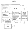
- an entertainment system 10 of this embodiment has an optical disk reproducing portion 1, an arithmetic processing unit 2, card type external storage receiving portions 3a, 3b, operating unit connecting portions 4a, 4b, a switch 11, and a display connecting portion 5, etc. These portions and a unit accommodated in a housing 10a of such a shape as shown in Figs. 1 and 4.
- the housing 10a is provided on a bottom surface thereof with feet 140, 141 used when the entertainment system 10 is set in a horizontally elongated state, i.e., in a lying state as shown in Fig. 1, and on a side surface thereof with feet 150, 151 used when the entertainment system 10 is set in a vertically elongated state, i.e., in a standing state as shown in Fig. 4.
- the optical disk reproducing portion 3 is a device for reproducing an optical disk 608 on which a game program and image information to be displayed are recorded in advance, and provided with a disk tray 101 for placing an optical disk 608 therein, a body 102 and a switch 103, etc.
- the disk tray 101 is arranged in a disk tray inserting opening 12 provided in a front surface of the housing 10a of the entertainment system 10.
- the body 102 of the optical disk reproducing unit 1 is provided on the inner side of the opening 12.
- This body 102 is provided therein with a mechanism including a rack and a pinion, etc. for withdrawing the disk tray 101 from the opening 12 to the outside and retracting the disk tray 101 from the opening 12 into the interior of the housing 10a, and provided with a driving power source.
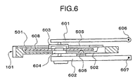
- the body 102 is also provided therein with an optical disk rotating mechanism, a reproducing head 605 and a reproducing circuit, etc. which are shown in Fig. 6.
- the optical disk rotating mechanism includes a disk clamper 603, a disk table 604, support frames 601, 602 for supporting the clamper 603 and table 604, and a driving power source (not shown), etc.
- the switch 103 is a switch for giving instructions to draw out and retract the disk tray 101, this switch being provided on a front surface of the housing 10a.
- the switch 103 is connected to the driving power source, which is provided in the unit body 102, for the rack and pinion.
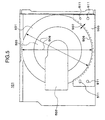
- the disk tray 101 is provided with a circular recess 501 in which an optical disk 608 is to be placed.
- the recess 501 is formed to a diameter slightly larger than that of the optical disk 608.
- a depth of a central portion 503 of the recess 501 is set larger.
- the disk tray 101 has a reception member 505 fixed thereto as shown in Figs. 4 and 5, which reception member 505 receives and supports a lower edge of the optical disk 608 when the entertainment system 10 is set vertically, to prevent the optical disk 608 from coming off and falling from the recess 501.
- the reception member 505 is fixed by engaging four projections 511 with holes made in the disk tray 101.
- the reception member 505 has a size large enough to cover about 1/3 of an outer circumference of the recess 501, and is formed so that an edge 506 of the same member 505 projects inward beyond the outer circumference of the recess 501 by a predetermined distance 507. Accordingly, the edge 506 is formed concentrically circles with the outer circumference of the recess 501.
- a position in which the reception member 505 is fixed is on the lower side of the recess 501 of the disk tray 101 in the entertainment system 10 vertically set.
- the distance 507 of the reception member 505 is designed with consideration given to the length of the portion of the outer circumference of the recess 501 which the reception member 505 covers, in such a manner that the distance 507 by which the reception member 505 projects be large enough to prevent the optical disk 608 from slipping and falling.
- the reception member 505 covers around 1/3 of the outer circumference of the recess as mentioned above. Therefore, even when the distance 507 by which the reception member 505 projects is several millimeters as shown in Fig. 5, the slipping and falling of the optical disk 608 can be prevented.
- diameters 508 of the portions of a bottom surface of the recess 501 of the disk tray 101 in this embodiment which are not covered with the reception member 505 can be securely set substantially equal to or slightly larger than that of the optical disk 608. Accordingly, during an operation for placing the disk 608 in the recess 501, the user does not have to be conscious of the reception member 505, i.e., the optical disk 608 may be placed on the portion of the bottom surface of the recess 501 which is not covered with the reception member 505. Consequently, when the entertainment system 10 is vertically set, the edge portion of the optical disk 608 slides by its own weight into a clearance between the reception member 505 and recess 501, so that the optical disk 608 is retained in a vertically extending state.
- the reception member 505 is made of a material the softness of which is equal to or higher than that of the material out of which the optical disk 608 is formed, so that the reception member 505 more rarely gives flaws to the optical disk 608.
- the depth of the recess 501 is set larger than the thickness of the optical disk 608.
- the positions in which the disk clamper 603 and disk table 604 hold the optical disk 608 are set so that the optical disk 608 is held in an intermediate portion with respect to the depth of the recess 501 as shown in Fig. 6. Accordingly, during the reproduction of the optical disk 608, the optical disk is rotated without contacting both the bottom surface of the recess 501 and the reception member 505.
- the disk tray 101 is provided with an opening 502 formed by cutting out a bottom wall of the recess 501 in the radial direction thereof.
- the optical head 605 is inserted into the opening 502.
- the front surface of the housing 10a of the entertainment system 10 is provided with card type external storage receiving portions 3a, 3b and operating unit connecting portions 4a, 4b arranged vertically respectively.
- the receiving portions 3a, 3b are capable of having card type external storages 30, in which the information on a game corresponding to each of operators, such as the progressing condition of a game is stored, connected thereto.
- the arithmetic processing unit 2 is capable of communicating with a connected external storage 30 to deliver the game information thereto and store the information in the same, and reading the game information stored in the external storage 30.
- Operating units 20 shown in Fig. 2 are connected to the operating unit connectingportions 4a, 4b.
- Each operating unit 20 includes a connector 21, operating member 22 and a cable 23.
- the operating member 22 is provided with various switches 18, 19, 24-29.
- the connectors 21 are inserted into the connecting portions 4a, 4b and connected thereto. Up to two operating units 20 can be connected to the entertainment system 10.
- One card type external storage can be connected to the entertainment system 10 corresponding to one operating unit 20.
- the front surface of the housing 10a is provided with a reset button 11 for giving instructions to reset a game to the arithmetic processing unit 2.
- a rear surface of the housing 10a is provided with a connecting portion 5 for connecting an external display 40 thereto, a power switch (not shown), etc.
- a user turns on the power switch, and then presses down the switch 103 on the front surface of the housing 10a to project the disk tray 101 from the housing 10a.
- the user then places the optical disk 608, on which a program, etc. of a game is recorded, in the recess 501 of the disk tray 101.
- the user may not substantially be conscious of the reception member 505.
- the entertainment system 10 is set vertically, and when the entertainment system 10 is set horizontally, the user may move the optical disk 608 to the bottom surface of the recess 501 and separate his hand from the optical disk 608 with the optical disk 608 left lying along the bottom surface of the recess 501.
- the entertainment system 10 is set vertically as shown in Fig.
- the optical disk 608 slides down along the bottom surface of the recess 501 by its own weight, and the lower edge portion of the optical disk 608 slips into a clealance between the reception member 505 and the recess 501, the optical disk 608 being thereby retained by the reception member 505. Therefore, the optical disk 608 is retained in the disk tray 101 in a substantially vertically extending state without falling from the recess 501.
- the optical disk 608 is placed as it is in the bottom surface of the recess 501.
- the optical disk 608, disk tray 101 and all are loaded into the body 102 with the optical disk 608 kept substantially vertical by the reception member 505.
- the optical disk 608, disk tray 101 and all are loaded into the body 102 with the optical disk 608 left retained horizontally by the bottom surface of the recess 501.
- support frames 601, 602 are turned around support shafts 606, 607 by an operation of a driving mechanism in the body 102, and the optical disk 608 is retained (Fig. 6) by the disk clamper 603 from the side of the upper surface thereof, and by the disk table 604 from the surface thereof which is on the side of the opening 502 of the disk tray 101.
- the optical disk 608 is retained in a sandwiched state in a correct position without a fear of unexpectedly contacting the disk clamper 603, etc. since the optical disk 608 is held along the disk tray 101 by the reception member 505.
- the disk clamper 603 and disk table 604 are adapted to turn the optical disk 608, while the optical head 605 is adapted to move from the opening 502 of the disk tray 101 and approach a rear surface of the rotating optical disk 608 to read the information recorded on the optical disk 608.
- the optical disk 608 is rotated without contacting the bottom surface of the recess 501 and reception member 505 since the position in which the optical disk 608 is held is in an intermediate portion of the recess 501 with respect to the direction of the depth thereof.
- the reproducing circuit in the body 102 is adapted to reproduce a game program, image information, etc. to be displayed from an output from the optical head 605, and deliver the reproduced information to the arithmetic unit 2.
- the arithmetic processing unit 2 is adapted to form an image from the image information to be displayed which is received from the optical disk reproducing portion 1, and shows the image on the display 40 via the connecting portion 5.
- the arithmetic processing unit 2 is also adapted to receive via the connecting portions 4a, 4b an operation of the operating unit 20 carried out by the user, and execute the program in accordance with the operation, whereby a game forwarding image is re-formed and shown on the display 40 to vary the displayed image.
- the arithmetic processing unit 2 is further adapted to communicate with the card type external storages 30, which are connected to the receiving portions 3a, 3b, in accordance with the program to carry out the reading or storing of game information.
- the optical disk reproducing unit 1 of the entertainment system 10 of this embodiment is provided with the reception member 505 having the arcuate edge 506 and fixed to the disk tray 101. Accordingly, even when the entertainment system 10 is set vertically or horizontally, the optical disk 608 can be retained vertically or horizontally in the disk tray 101 by a mere operation for placing the optical disk 608 along the edge 506. Therefore, unlike a related art entertainment system, the troublesome operations for sliding an edge portion of an optical disk into pockets, engaging an edge portion of an optical disk with hooks, and fixing a disk cover are unnecessary. This enables the optical disk 608 to be placed in the disk tray 101 simply both when the entertainment system 10 is set vertically and when the entertainment system 10 is set horizontally. Since the edge 506 of the reception member 505 is arcuate, there is not the possibility that the edge 506 gives flaws to the optical disk 608. Consequently, a user's operation for placing the optical disk 608 in the disk tray can be carried out more easily.
- the reception member 505 of the optical disk reproducing unit 1 of this embodiment is one member, so that the fixing thereof becomes advantageously easy. Since the reception member 505 has an arcuate edge 506 and simple structure so that complicated structures, such as the hooks, and a detachable structure, such as the cover in the related art entertainment system are not required. Consequently, the reception member 505 can be manufactured at a low cost with ease.
- a method of fixing the reception member 505 is not limited to this method. It is possible to use, for example, a method of fixing the reception member 505 by screws instead of the projections 511, a method of fixing the reception member 505 by gluing the same to the disk tray 101 with glue material, and a fixing method using both screws and glue material. It is also possible to fix the reception member 505 to the disk tray 101 by fusing the contact surfaces thereof.
- the diameters 508 of the portion of the bottom surface of the recess 501 of the disk tray 101 which is not covered with the reception member 505 are set equal to or slightly larger than that of the optical disk 608 so that the optical disk 608 can be placed on the portion of the mentioned bottom surface not covered with the reception member 505 but the present invention is not limited to this structure.
- the edge of the optical disk 608 which is on the side of the reception member 505 reaches the bottom surface of the recess 501, and the edge on the opposite side of the optical disk 608 gets on an edge of the recess 501, so that the optical disk 608 inclines, whereby the edge of the optical disk 608 slides by its own weight into the reception member 505. Therefore, not only when the entertainment system is set vertically but also when the entertainment system is set horizontally, the edge of the optical disk 608 merely placed on the disk tray 101 slides into the reception member 505, in which the optical disk 608 can be retained.
- the optical disk 608 can be retained vertically or horizontally in the disk tray 101 by a simple action, i.e., by merely placing the optical disk 608 in the disk tray. In this case, it is also possible to form a side surface of the recess 501 incliningly so that the edge portion of the optical disk 608 slides more easily into the reception member 505.
- an information processing system having a disk device which is capable of placing a disk in a disk tray easily both when the system is set horizontally and when the system is set vertically.
- the information processing system according to the present invention is useful as an information processing system having a disk device capable of placing a disk in a disk tray easily both when the system is set horizontally and when the system is set vertically.
Landscapes
- Feeding And Guiding Record Carriers (AREA)
- Holding Or Fastening Of Disk On Rotational Shaft (AREA)
Abstract
An information processing system comprising a disk device
is provided which is capable of placing a disk on a disk tray
easily both when the system is set horizontally and when the
system is set vertically. This system is provided with a disk
device having a disk tray for placing a disk type recording medium
therein, and a recording medium reproducing portion for drawing
thereinto the disk tray on which said recording medium is mounted
and reproducing said recording medium. The disk tray has a recess
used to place the recording medium therein and having a circular
outer circumference, and a reception member projecting from the
outer circumference of the recess in the inward direction so
as to retain an edge portion of the recording medium. The edge
of the reception member extends curvilinearly along the outer
circumference of the recess.
Description
This invention relates to an information processing
system provided with a disk reproducing apparatus, and more
particularly to an entertainment system provided with an optical
disk reproducing apparatus.
Known disk reproducing apparatuses, such as a CD-ROM
include an apparatus of the type in which an upper cover covering
a disk mounting portion is opened then placed a disk on this
portion, and a loading type apparatus in which a disk tray is
drawn out from an apparatus body toward a user then inserted
a disk into a recess in an upper surface of the tray, which the
disk-mounted tray as a whole is then put into the apparatus body.
The loading type disk reproducing apparatuses include a so-called
vertically settable apparatus capable of being used in an upright
standing state so as to minimize a space for the installation
thereof. However, when the apparatus is vertically set, a disk
mounting surface of the disk tray also becomes vertical, so that
the disk is liable to slip from the disk tray.
Japanese Patent Laid-Open No. 6-251479 discloses a disk
unit in which parts of an outer circumferential portion of the
disk are fitted loosely in pockets provided in several parts
of an outer circumferential portions of a recess of a disk tray,
so as to solve this problem. Aplate type member the main surface
portion of which is rectangular is disclosed as a member showing
a concrete shape of each pocket, and such plate type members
are provided so as to project over several parts of the
circumferential portion of the disk and hold the same. This
publication also discloses a structure for holding a disk by
engaging retractable hooks with an outer circumferential portion
of the disk. Japanese Patent Laid-Open No. 7-326177 discloses
a disk unit in which a disk is placed in a disk tray with a detachable
cover then attached thereto so as to cover a part of the disk
and thereby prevent the disk from slipping off.
In the disk unit disclosed in Japanese Patent Laid-Open
No. 6-251479 and having pockets formed by projecting rectangular
plate type members over an outer circumferential portion of a
disk, it is necessary during the placing of the disk in a disk
tray that the disk be slid into a clearance between the rectangular
plate type members and disk tray. Therefore, even when a disk
unit is set not vertically but horizontally, an operation for
sliding the disk into such a clearance is required, so that a
disk setting operation becomes complicated. Regarding the
retractable hooks, it is necessary that the disk be mounted as
the disk is positioned so that an edge of the disk engages the
hooks. Accordingly, during the setting of a disk, a disk aligning
operation has to be carried out consciously. The retractable
hooks have to be provided with a structure for rendering the
same retractable, so that the construction of the hooks is
complicated.
The detachable cover disclosed in Japanese Patent
Laid-Open No. 7-326177 is formed separately from the disk tray.
Therefore, every time the disk is placed in or removed from the
disk tray, cover attaching or detaching operation has to be
carried out. This causes an operation for placing the disk in
the disk tray to become very complicated.
It is an object of the present invention to provide an
information processing system having a disk device capable of
placing a disk on a disk tray easily even when the disk unit
is set horizontally or vertically.
In order to achieve the above-described object, an
information processing system provided with a disk device
according to the present invention is provided, having the
following features.
That is, it is provided an information processing system
comprising a disk device, wherein,
Preferred embodiments of the present invention will be
described in detail on the basis of the following figures,
wherein:
One embodiment of the entertainment system provided with
an optical disk reproducing device according to the present
invention will now be described.
As shown in Figs. 1, 3 and 4, an entertainment system
10 of this embodiment has an optical disk reproducing portion
1, an arithmetic processing unit 2, card type external storage
receiving portions 3a, 3b, operating unit connecting portions
4a, 4b, a switch 11, and a display connecting portion 5, etc.
These portions and a unit accommodated in a housing 10a of such
a shape as shown in Figs. 1 and 4. The housing 10a is provided
on a bottom surface thereof with feet 140, 141 used when the
entertainment system 10 is set in a horizontally elongated state,
i.e., in a lying state as shown in Fig. 1, and on a side surface
thereof with feet 150, 151 used when the entertainment system
10 is set in a vertically elongated state, i.e., in a standing
state as shown in Fig. 4.
The optical disk reproducing portion 3 is a device for
reproducing an optical disk 608 on which a game program and image
information to be displayed are recorded in advance, and provided
with a disk tray 101 for placing an optical disk 608 therein,
a body 102 and a switch 103, etc. The disk tray 101 is arranged
in a disk tray inserting opening 12 provided in a front surface
of the housing 10a of the entertainment system 10. On the inner
side of the opening 12, the body 102 of the optical disk reproducing
unit 1 is provided. This body 102 is provided therein with a
mechanism including a rack and a pinion, etc. for withdrawing
the disk tray 101 from the opening 12 to the outside and retracting
the disk tray 101 from the opening 12 into the interior of the
housing 10a, and provided with a driving power source. The body
102 is also provided therein with an optical disk rotating
mechanism, a reproducing head 605 and a reproducing circuit,
etc. which are shown in Fig. 6. The optical disk rotating
mechanism includes a disk clamper 603, a disk table 604, support
frames 601, 602 for supporting the clamper 603 and table 604,
and a driving power source (not shown), etc.
The switch 103 is a switch for giving instructions to
draw out and retract the disk tray 101, this switch being provided
on a front surface of the housing 10a. The switch 103 is connected
to the driving power source, which is provided in the unit body
102, for the rack and pinion.
As shown in Figs. 5 and 6, the disk tray 101 is provided
with a circular recess 501 in which an optical disk 608 is to
be placed. The recess 501 is formed to a diameter slightly larger
than that of the optical disk 608. A depth of a central portion
503 of the recess 501 is set larger.
The disk tray 101 has a reception member 505 fixed thereto
as shown in Figs. 4 and 5, which reception member 505 receives
and supports a lower edge of the optical disk 608 when the
entertainment system 10 is set vertically, to prevent the optical
disk 608 from coming off and falling from the recess 501. The
reception member 505 is fixed by engaging four projections 511
with holes made in the disk tray 101.
The reception member 505 has a size large enough to cover
about 1/3 of an outer circumference of the recess 501, and is
formed so that an edge 506 of the same member 505 projects inward
beyond the outer circumference of the recess 501 by a
predetermined distance 507. Accordingly, the edge 506 is formed
concentrically circles with the outer circumference of the recess
501.
A position in which the reception member 505 is fixed
is on the lower side of the recess 501 of the disk tray 101 in
the entertainment system 10 vertically set. The distance 507
of the reception member 505 is designed with consideration given
to the length of the portion of the outer circumference of the
recess 501 which the reception member 505 covers, in such a manner
that the distance 507 by which the reception member 505 projects
be large enough to prevent the optical disk 608 from slipping
and falling. In this embodiment, the reception member 505 covers
around 1/3 of the outer circumference of the recess as mentioned
above. Therefore, even when the distance 507 by which the
reception member 505 projects is several millimeters as shown
in Fig. 5, the slipping and falling of the optical disk 608 can
be prevented. Since the distance 507 by which the reception
member 505 projects is thus small, diameters 508 of the portions
of a bottom surface of the recess 501 of the disk tray 101 in
this embodiment which are not covered with the reception member
505 can be securely set substantially equal to or slightly larger
than that of the optical disk 608. Accordingly, during an
operation for placing the disk 608 in the recess 501, the user
does not have to be conscious of the reception member 505, i.e.,
the optical disk 608 may be placed on the portion of the bottom
surface of the recess 501 which is not covered with the reception
member 505. Consequently, when the entertainment system 10 is
vertically set, the edge portion of the optical disk 608 slides
by its own weight into a clearance between the reception member
505 and recess 501, so that the optical disk 608 is retained
in a vertically extending state.
Since the edge 506 of the reception member 505 is circular,
the reception member rarely gives flaws, etc. to the optical
disk 608, etc. Further, in this embodiment, the reception member
505 is made of a material the softness of which is equal to or
higher than that of the material out of which the optical disk
608 is formed, so that the reception member 505 more rarely gives
flaws to the optical disk 608.
The depth of the recess 501 is set larger than the thickness
of the optical disk 608. The positions in which the disk clamper
603 and disk table 604 hold the optical disk 608 are set so that
the optical disk 608 is held in an intermediate portion with
respect to the depth of the recess 501 as shown in Fig. 6.
Accordingly, during the reproduction of the optical disk 608,
the optical disk is rotated without contacting both the bottom
surface of the recess 501 and the reception member 505.
The disk tray 101 is provided with an opening 502 formed
by cutting out a bottom wall of the recess 501 in the radial
direction thereof. When the disk tray 101 is drawn into the
body 102 to reproduce the optical disk 608, the optical head
605 is inserted into the opening 502.
The front surface of the housing 10a of the entertainment
system 10 is provided with card type external storage receiving
portions 3a, 3b and operating unit connecting portions 4a, 4b
arranged vertically respectively. The receiving portions 3a,
3b are capable of having card type external storages 30, in which
the information on a game corresponding to each of operators,
such as the progressing condition of a game is stored, connected
thereto. The arithmetic processing unit 2 is capable of
communicating with a connected external storage 30 to deliver
the game information thereto and store the information in the
same, and reading the game information stored in the external
storage 30. Operating units 20 shown in Fig. 2 are connected
to the operating unit connectingportions 4a, 4b. Each operating
unit 20 includes a connector 21, operating member 22 and a cable
23. The operating member 22 is provided with various switches
18, 19, 24-29. The connectors 21 are inserted into the connecting
portions 4a, 4b and connected thereto. Up to two operating units
20 can be connected to the entertainment system 10. One card
type external storage can be connected to the entertainment system
10 corresponding to one operating unit 20.
The front surface of the housing 10a is provided with
a reset button 11 for giving instructions to reset a game to
the arithmetic processing unit 2. A rear surface of the housing
10a is provided with a connecting portion 5 for connecting an
external display 40 thereto, a power switch (not shown), etc.
The procedure for operating and an action of each part
of the entertainment system 10 of such a construction of this
embodiment during a game played by the same system will now be
described.
First, a user turns on the power switch, and then presses
down the switch 103 on the front surface of the housing 10a to
project the disk tray 101 from the housing 10a. The user then
places the optical disk 608, on which a program, etc. of a game
is recorded, in the recess 501 of the disk tray 101. During
this time, the user may not substantially be conscious of the
reception member 505. Both when the entertainment system 10
is set vertically, and when the entertainment system 10 is set
horizontally, the user may move the optical disk 608 to the bottom
surface of the recess 501 and separate his hand from the optical
disk 608 with the optical disk 608 left lying along the bottom
surface of the recess 501. When the entertainment system 10
is set vertically as shown in Fig. 4, the optical disk 608 slides
down along the bottom surface of the recess 501 by its own weight,
and the lower edge portion of the optical disk 608 slips into
a clealance between the reception member 505 and the recess 501,
the optical disk 608 being thereby retained by the reception
member 505. Therefore, the optical disk 608 is retained in the
disk tray 101 in a substantially vertically extending state
without falling from the recess 501. In the case of the
entertainment system 10 being set horizontally, when the user
separates his hand from the optical disk 608, the optical disk
608 is placed as it is in the bottom surface of the recess 501.
When the user presses down the switch 103 again or presses
the disk tray 101 to retract the disk tray 101 into the body
102, in the case of the entertainment system 10 being set
vertically, the optical disk 608, disk tray 101 and all are loaded
into the body 102 with the optical disk 608 kept substantially
vertical by the reception member 505. When the entertainment
system 10 is set horizontally in this case, the optical disk
608, disk tray 101 and all are loaded into the body 102 with
the optical disk 608 left retained horizontally by the bottom
surface of the recess 501.
With the retraction of the disk tray 101, support frames
601, 602 are turned around support shafts 606, 607 by an operation
of a driving mechanism in the body 102, and the optical disk
608 is retained (Fig. 6) by the disk clamper 603 from the side
of the upper surface thereof, and by the disk table 604 from
the surface thereof which is on the side of the opening 502 of
the disk tray 101. Even when the entertainment system 10 is
set vertically in this case, the optical disk 608 is retained
in a sandwiched state in a correct position without a fear of
unexpectedly contacting the disk clamper 603, etc. since the
optical disk 608 is held along the disk tray 101 by the reception
member 505.
The disk clamper 603 and disk table 604 are adapted to
turn the optical disk 608, while the optical head 605 is adapted
to move from the opening 502 of the disk tray 101 and approach
a rear surface of the rotating optical disk 608 to read the
information recorded on the optical disk 608. During this time,
the optical disk 608 is rotated without contacting the bottom
surface of the recess 501 and reception member 505 since the
position in which the optical disk 608 is held is in an intermediate
portion of the recess 501 with respect to the direction of the
depth thereof. The reproducing circuit in the body 102 is adapted
to reproduce a game program, image information, etc. to be
displayed from an output from the optical head 605, and deliver
the reproduced information to the arithmetic unit 2.
The arithmetic processing unit 2 is adapted to form an
image from the image information to be displayed which is received
from the optical disk reproducing portion 1, and shows the image
on the display 40 via the connecting portion 5. The arithmetic
processing unit 2 is also adapted to receive via the connecting
portions 4a, 4b an operation of the operating unit 20 carried
out by the user, and execute the program in accordance with the
operation, whereby a game forwarding image is re-formed and shown
on the display 40 to vary the displayed image. The arithmetic
processing unit 2 is further adapted to communicate with the
card type external storages 30, which are connected to the
receiving portions 3a, 3b, in accordance with the program to
carry out the reading or storing of game information.
As has been described above, the optical disk reproducing
unit 1 of the entertainment system 10 of this embodiment is
provided with the reception member 505 having the arcuate edge
506 and fixed to the disk tray 101. Accordingly, even when the
entertainment system 10 is set vertically or horizontally, the
optical disk 608 can be retained vertically or horizontally in
the disk tray 101 by a mere operation for placing the optical
disk 608 along the edge 506. Therefore, unlike a related art
entertainment system, the troublesome operations for sliding
an edge portion of an optical disk into pockets, engaging an
edge portion of an optical disk with hooks, and fixing a disk
cover are unnecessary. This enables the optical disk 608 to
be placed in the disk tray 101 simply both when the entertainment
system 10 is set vertically and when the entertainment system
10 is set horizontally. Since the edge 506 of the reception
member 505 is arcuate, there is not the possibility that the
edge 506 gives flaws to the optical disk 608. Consequently,
a user's operation for placing the optical disk 608 in the disk
tray can be carried out more easily.
When disk edge holding plate type members for pockets
or disk edge engageable hooks are used as in a related art
entertainment system, these parts have to be provided in at least
two positions. However, the reception member 505 of the optical
disk reproducing unit 1 of this embodiment is one member, so
that the fixing thereof becomes advantageously easy. Since the
reception member 505 has an arcuate edge 506 and simple structure
so that complicated structures, such as the hooks, and a
detachable structure, such as the cover in the related art
entertainment system are not required. Consequently, the
reception member 505 can be manufactured at a low cost with ease.
Although the reception member 505 is fixed to the disk
tray 101 by engaging four projections 511 with a disk tray 101
in the above-described embodiment, a method of fixing the
reception member 505 is not limited to this method. It is possible
to use, for example, a method of fixing the reception member
505 by screws instead of the projections 511, a method of fixing
the reception member 505 by gluing the same to the disk tray
101 with glue material, and a fixing method using both screws
and glue material. It is also possible to fix the reception
member 505 to the disk tray 101 by fusing the contact surfaces
thereof.
In the above-described embodiment, the diameters 508 of
the portion of the bottom surface of the recess 501 of the disk
tray 101 which is not covered with the reception member 505 are
set equal to or slightly larger than that of the optical disk
608 so that the optical disk 608 can be placed on the portion
of the mentioned bottom surface not covered with the reception
member 505 but the present invention is not limited to this
structure. The reasons reside in the following. Even when the
diameters 508 of the portion of the bottom surface of the recess
501 which is not covered with the reception member 505 is smaller
than that of the optical disk 608, the optical disk 608 can be
placed easily in the bottom of the recess 501 along the edge
506 of the reception member 505 since the reception member 505
in this embodiment is arcuate. Owing to this structure, the
edge of the optical disk 608 which is on the side of the reception
member 505 reaches the bottom surface of the recess 501, and
the edge on the opposite side of the optical disk 608 gets on
an edge of the recess 501, so that the optical disk 608 inclines,
whereby the edge of the optical disk 608 slides by its own weight
into the reception member 505. Therefore, not only when the
entertainment system is set vertically but also when the
entertainment system is set horizontally, the edge of the optical
disk 608 merely placed on the disk tray 101 slides into the
reception member 505, in which the optical disk 608 can be retained.
Accordingly, even when the diameters 508 of the portion of the
bottom surface of the recess 501 which is not covered with the
reception member 505 is smaller than the diameter of the optical
disk 608, the optical disk 608 can be retained vertically or
horizontally in the disk tray 101 by a simple action, i.e., by
merely placing the optical disk 608 in the disk tray. In this
case, it is also possible to form a side surface of the recess
501 incliningly so that the edge portion of the optical disk
608 slides more easily into the reception member 505.
According to the present invention described above, an
information processing system having a disk device can be provided
which is capable of placing a disk in a disk tray easily both
when the system is set horizontally and when the system is set
vertically.
As described above, the information processing system
according to the present invention is useful as an information
processing system having a disk device capable of placing a disk
in a disk tray easily both when the system is set horizontally
and when the system is set vertically.
Claims (14)
- An information processing system comprising a disk device, wherein:said disk device has a disk tray for placing a disk type recording medium therein, and a recording medium reproducing portion for drawing thereinto said disk tray on which the recording medium mounted and for reproducing said recording medium:said disk tray has a recess which has a circular outer circumference for placing said recording medium thereon, and a reception member projecting from the outer circumference of said recess in the inward direction for retaining a circumferential edge portion of said recording medium: andan edge portion of said reception member has a curvilinear shape along said outer circumference of said recess.
- An information processing system according to Claim 1, wherein said edge portion of the reception member has an arcuate shape concentric with a circular shape of said outer circumference of said recess.
- An information processing system according to Claim 1, wherein a diameter of a portion of a bottom surface of said recess which is not covered with said reception member is equal to or larger than that of said recording medium.
- An information processing system according to Claim 1, further comprising;a housing in which the reproducing unit is provided, the housing being provided with a foot for laying the housing which are used to set the housing so that a main flat surface of said disk tray becomes horizontal, and a foot for standing the housing which are used to set the housing so that the main flat surface of the disk tray becomes vertical,said reception member being provided to a portion of said disk tray which is positioned on a lower section of said disk tray when the housing is set by using said foot for standing the housing.
- An information processing unit according to Claim 1, wherein said reception member covers not smaller than 1/3 of said outer circumference of said recess.
- A disk device comprising:a disk tray for placing a disk type recording medium therein, and a recording medium reproducing portion for drawing thereinto said disk tray on which the recording medium is mounted and reproducing said recording medium;said disk tray including a recess which has a circular outer circumference for placing said recording medium therein, and a reception member projecting from the outer circumference of said recess in the inward direction for retaining a circumferential edge portion of said recording medium; andan edge portion of said reception member having a curvilinear shape along said outer circumference of said recess.
- A disk unit according to Claim 6, wherein said edge portion of the reception member has an arcuate shape concentric with a circular shape of said outer circumference of said recess .
- A disk unit according to Claim 6, wherein a diameter of a portion of a bottom surface of said recess which is not covered with said reception member is equal to or larger than that of said recording medium.
- A disk unit according to Claim 6 further comprising;a housing in which the reproducing unit is provided, the housing being provided with a foot for laying the housing which are used to set the housing so that a main flat surface of said disk tray becomes horizontal, and a foot for standing the housing which are used to set the housing so that the main flat surface of the disk tray becomes vertical,said reception member being provided to a portion of said disk tray which is positioned on a lower section of said disk tray when the housing is set by using said foot for standing the housing.
- A disk unit according to Claim 6, wherein said reception member covers not smaller than 1/3 of said outer circumference of said recess.
- A disk tray for placing a disk type recording medium therein, comprising:a recess which has a circular outer circumference for placing said recording medium therein, and a reception member projecting from the outer circumference of said recess in the inward direction for retaining a circumferential edge portion of said recording medium; andan edge portion of said reception member having a curvilinear shape along said outer circumference of said recess .
- A disk tray according to Claim 11, wherein said edge portion of the reception member has an arcuate shape concentric with a circular shape of said outer circumference of said recess.
- A disk tray according to Claim 11, wherein a diameter of a portion of a bottom surface of said recess which is not covered with said reception member is equal to or larger than that of said recording medium.
- A disk tray according to Claim 11, wherein said reception member covers not smaller than 1/3 of said outer circumference of said recess.
Applications Claiming Priority (3)
| Application Number | Priority Date | Filing Date | Title |
|---|---|---|---|
| JP25181699A JP2001076407A (en) | 1999-09-06 | 1999-09-06 | Information processing device having disk device, disk device and disk tray |
| JP25181699 | 1999-09-06 | ||
| PCT/JP2000/006061 WO2001018805A1 (en) | 1999-09-06 | 2000-09-06 | Information processor with disk device, disk device and disk tray |
Publications (2)
| Publication Number | Publication Date |
|---|---|
| EP1221697A1 true EP1221697A1 (en) | 2002-07-10 |
| EP1221697A4 EP1221697A4 (en) | 2005-10-12 |
Family
ID=17228356
Family Applications (1)
| Application Number | Title | Priority Date | Filing Date |
|---|---|---|---|
| EP00956972A Withdrawn EP1221697A4 (en) | 1999-09-06 | 2000-09-06 | Information processor with disk device, disk device and disk tray |
Country Status (7)
| Country | Link |
|---|---|
| EP (1) | EP1221697A4 (en) |
| JP (1) | JP2001076407A (en) |
| KR (1) | KR20030009293A (en) |
| CN (1) | CN1372685A (en) |
| AU (1) | AU6872300A (en) |
| CA (1) | CA2384159A1 (en) |
| WO (1) | WO2001018805A1 (en) |
Families Citing this family (1)
| Publication number | Priority date | Publication date | Assignee | Title |
|---|---|---|---|---|
| WO2002086883A1 (en) * | 2001-04-16 | 2002-10-31 | Sony Corporation | Disk holding member, disk tray, recording and/or reproducing device, and disk changer |
Family Cites Families (4)
| Publication number | Priority date | Publication date | Assignee | Title |
|---|---|---|---|---|
| JPS467649Y1 (en) * | 1968-08-08 | 1971-03-18 | ||
| JPH0855400A (en) * | 1994-08-10 | 1996-02-27 | Sanyo Electric Co Ltd | Tray for disk player |
| JP3404925B2 (en) * | 1994-10-24 | 2003-05-12 | ミツミ電機株式会社 | Disk unit |
| JPH1139762A (en) * | 1997-07-15 | 1999-02-12 | Victor Co Of Japan Ltd | Disk tray |
-
1999
- 1999-09-06 JP JP25181699A patent/JP2001076407A/en active Pending
-
2000
- 2000-09-06 EP EP00956972A patent/EP1221697A4/en not_active Withdrawn
- 2000-09-06 CN CN00812527A patent/CN1372685A/en active Pending
- 2000-09-06 KR KR1020027002739A patent/KR20030009293A/en not_active Withdrawn
- 2000-09-06 WO PCT/JP2000/006061 patent/WO2001018805A1/en not_active Ceased
- 2000-09-06 AU AU68723/00A patent/AU6872300A/en not_active Abandoned
- 2000-09-06 CA CA002384159A patent/CA2384159A1/en not_active Abandoned
Also Published As
| Publication number | Publication date |
|---|---|
| WO2001018805A1 (en) | 2001-03-15 |
| EP1221697A4 (en) | 2005-10-12 |
| KR20030009293A (en) | 2003-01-29 |
| AU6872300A (en) | 2001-04-10 |
| CA2384159A1 (en) | 2001-03-15 |
| CN1372685A (en) | 2002-10-02 |
| JP2001076407A (en) | 2001-03-23 |
Similar Documents
| Publication | Publication Date | Title |
|---|---|---|
| US4932522A (en) | CD storage with automatic opening device | |
| JP7537320B2 (en) | Audio Recorder | |
| US4114044A (en) | Radiographic cassette adapter | |
| EP1221697A1 (en) | Information processor with disk device, disk device and disk tray | |
| US3495839A (en) | Turntable recess for record removal | |
| JPH1097749A (en) | Storage and transfer device for information carrier | |
| JP4379093B2 (en) | Panel-shaped video display device | |
| US5913419A (en) | Combination of a support for a disc-shaped recording medium and a holder for the support | |
| JP2518296Y2 (en) | Recording / playback device | |
| JP2004103192A (en) | Optical disk device and electronic equipment | |
| JP5569103B2 (en) | Electronics | |
| JPH1145558A (en) | Remote control device and electronic equipment | |
| CN100429937C (en) | Display unit loading platform | |
| US20100081503A1 (en) | Video game system | |
| JPH082877Y2 (en) | Optical disk drive | |
| JP2001034402A (en) | Electronic equipment provided with a storage section for operating means | |
| US20030190009A1 (en) | Liquid crystal display with a built-in X-ray film reader | |
| JP2517967Y2 (en) | Telephone | |
| TW200907937A (en) | Storage device and electronic apparatus | |
| JPH11312350A (en) | Disk drive | |
| JPS60217575A (en) | Disc case | |
| JP3246191B2 (en) | Front panel for enclosure for disc player device | |
| KR100728505B1 (en) | Detachable car multimedia player Gaming device using the front panel | |
| JP2001250305A (en) | Optical disk device | |
| JP2006073160A (en) | Optical disk device |
Legal Events
| Date | Code | Title | Description |
|---|---|---|---|
| PUAI | Public reference made under article 153(3) epc to a published international application that has entered the european phase |
Free format text: ORIGINAL CODE: 0009012 |
|
| 17P | Request for examination filed |
Effective date: 20020322 |
|
| AK | Designated contracting states |
Kind code of ref document: A1 Designated state(s): AT BE CH CY DE DK ES FI FR GB GR IE IT LI LU MC NL PT SE |
|
| AX | Request for extension of the european patent |
Free format text: AL;LT;LV;MK;RO;SI |
|
| A4 | Supplementary search report drawn up and despatched |
Effective date: 20050829 |
|
| STAA | Information on the status of an ep patent application or granted ep patent |
Free format text: STATUS: THE APPLICATION IS DEEMED TO BE WITHDRAWN |
|
| 18D | Application deemed to be withdrawn |
Effective date: 20060311 |