EP1221558A2 - Disc brake rotor - Google Patents
Disc brake rotor Download PDFInfo
- Publication number
- EP1221558A2 EP1221558A2 EP01204980A EP01204980A EP1221558A2 EP 1221558 A2 EP1221558 A2 EP 1221558A2 EP 01204980 A EP01204980 A EP 01204980A EP 01204980 A EP01204980 A EP 01204980A EP 1221558 A2 EP1221558 A2 EP 1221558A2
- Authority
- EP
- European Patent Office
- Prior art keywords
- vanes
- rotor
- width
- inverted
- proximal
- Prior art date
- Legal status (The legal status is an assumption and is not a legal conclusion. Google has not performed a legal analysis and makes no representation as to the accuracy of the status listed.)
- Withdrawn
Links
Images


Classifications
-
- F—MECHANICAL ENGINEERING; LIGHTING; HEATING; WEAPONS; BLASTING
- F16—ENGINEERING ELEMENTS AND UNITS; GENERAL MEASURES FOR PRODUCING AND MAINTAINING EFFECTIVE FUNCTIONING OF MACHINES OR INSTALLATIONS; THERMAL INSULATION IN GENERAL
- F16D—COUPLINGS FOR TRANSMITTING ROTATION; CLUTCHES; BRAKES
- F16D65/00—Parts or details
- F16D65/0006—Noise or vibration control
-
- F—MECHANICAL ENGINEERING; LIGHTING; HEATING; WEAPONS; BLASTING
- F16—ENGINEERING ELEMENTS AND UNITS; GENERAL MEASURES FOR PRODUCING AND MAINTAINING EFFECTIVE FUNCTIONING OF MACHINES OR INSTALLATIONS; THERMAL INSULATION IN GENERAL
- F16D—COUPLINGS FOR TRANSMITTING ROTATION; CLUTCHES; BRAKES
- F16D65/00—Parts or details
- F16D65/02—Braking members; Mounting thereof
- F16D65/12—Discs; Drums for disc brakes
-
- F—MECHANICAL ENGINEERING; LIGHTING; HEATING; WEAPONS; BLASTING
- F16—ENGINEERING ELEMENTS AND UNITS; GENERAL MEASURES FOR PRODUCING AND MAINTAINING EFFECTIVE FUNCTIONING OF MACHINES OR INSTALLATIONS; THERMAL INSULATION IN GENERAL
- F16D—COUPLINGS FOR TRANSMITTING ROTATION; CLUTCHES; BRAKES
- F16D65/00—Parts or details
- F16D65/02—Braking members; Mounting thereof
- F16D2065/13—Parts or details of discs or drums
- F16D2065/1304—Structure
- F16D2065/1328—Structure internal cavities, e.g. cooling channels
Definitions
- the present invention relates generally to disc brake rotors as used in a vehicle braking system. More particularly, the invention relates to a vehicle brake rotor that incorporates a plurality of vanes designed to reduce noise generated in the brake system.
- Noise generated during a brake application has been increasing as the size of vehicles has been decreasing. Attempts have been made to reduce the noise generated using various systems and methods.
- One such technique involves the use of sound adsorption coatings on the pad assembly. While such coatings have some effectiveness, the addition of the coating adds cost to the manufacture and at times, undesirable noise occurs when the thickness of the coating has not been uniform.
- Another technique involves a disc brake pad assembly having clench tabs extending through rubber-like grommets in openings in a caliper housing leg so that the grommets are retained in the openings and the brake pad assembly is retained on the housing leg.
- the grommets provide a noise dampening action during braking to reduce noise.
- the mode shape is generally accepted or described by defining the pattern of nodes (loci of points of zero deformation) on the surface of the structure.
- nodes loci of points of zero deformation
- the mode shape of an annular circular plate includes nodal circles and diameters.
- a typical structure of a brake rotor includes a central disc portion that is adapted to be mounted to an axle of a vehicle as in known in the art, by fasteners.
- An extending portion typically connects one of a pair of rotor friction plates or cheeks to the central disc portion.
- An outboard plate is the portion of the rotor that includes a friction surface attached to the central disc portion adjacent to the wheel and faces outward from the vehicle body.
- An inboard plate faces inward toward the vehicle body.
- a plurality of vanes extend from an inner surface of the first or outboard plate to connect a second inboard plate thereto.
- the vanes are typically arranged in a radial fashion about the rotor.
- the vanes hold the first and second plates in a parallel, side-by-side relationship.
- vanes have an overall regular elongate, rod, coffin or rectangular shape with a generally constant width and cross-sectional area. In other words, many current vanes start out a rectangular cross-section at one end and remain rectangular throughout the longitudinal distance of the vane at an opposite end.
- a prior-art plate typically has a thickness or cross-section remaining substantially constant along the radial direction.
- a rotor may possess a number of inherent resonance modes.
- the rotor may generate vibrations including a mode characterized by radial (and potentially transverse and some tangential) displacement of the plates of the rotor.
- the rotor may generate vibrations in a mode referred to as an X-mode, characterized by mainly transverse (with some radial and tangential) displacement of the plates of the rotor.
- a transverse modal vector is defined by one nodal diameters at the friction radius of the rotor and X order nodal diameters defined by the number of transverse antinodes. Coupling of a radial and an X-mode in a rotor results in a hybrid mode vibration. In a hybrid mode, one plate exhibits radial mode behavior and the other plate exhibits X-mode behavior.
- An aspect present invention provides a rotor for a disc brake including a pair of friction plates arranged coaxially in a parallel, spaced-apart relationship and a plurality of vanes extending between the pair of friction plates.
- the vanes have a proximal end, a distal end and a mid-portion extending between the proximal end and the distal end.
- the proximal end of a plurality of the plurality of vanes include a first width, the mid-portion including a second width, the first width being substantially greater than the second width.
- first width of half the vanes is substantially greater than the second width.
- the first width of the other half of the vanes can be substantially the same as the second width.
- the first width of at least half the vanes can be from about 50 percent greater than the second width to about twice that of the second width.
- a plurality of the plurality of vanes can include an inverted T-shaped portion adjacent the proximal end of the vanes.
- Half of the vanes can include an inverted T-shaped portion adjacent the proximal end of the vanes.
- the inverted T-shaped portion is at least 50% wider than a width of the mid-portion.
- the rotor may further include an angled portion located between each inverted T-shaped portion and the mid-portion.
- An aspect of the present invention provide a method of reducing noise in a disc brake rotor including stiffening a radially inner portion of the brake rotor with a proximal portion of a plurality of vanes and reducing hybrid vibration modes in an audible frequency range.
- the proximal portion of the plurality of vanes can include an inverted T-shaped portion.
- Half of the plurality of vanes can include an inverted T-shaped portion at a proximal portion.
- the other half of the plurality of vanes can include a substantially constant width from a proximal portion to a distal portion of the vanes.
- a rotor for a disc brake including means for stiffening a radially inner portion of the brake rotor with a proximal portion of a plurality of vanes and means for reducing hybrid vibration modes in an audible frequency range.
- the proximal portion of the plurality of vanes can include an inverted T-shaped portion.
- Half of the plurality of vanes can include an inverted T-shaped portion at a proximal portion.
- the other half of the plurality of vanes can include a substantially constant width from a proximal portion to a distal portion of the vanes.
- the brake rotor 110 includes a central attachment portion 112 .
- An extending portion 114 is attached adjacent to the periphery 116 of the central attachment portion 114 .
- a first friction plate 118 (one of a pair of parallel friction plates) is depicted attached to the central attachment portion 112 by the extending portion 114 .
- a second friction plate (not shown), which would be oriented in a parallel, spaced apart relationship to the first plate 118 is omitted to show the structure (vanes) therebetween.
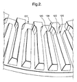
- a plurality of vanes 120 , 122 is provided that extend between the plates and are arranged in a radial fashion.
- the vanes 120 , 122 are radial members, each having a proximal end 124 , 126 adjacent the extending portion 114 and a middle span or mid-portion 128 , 130 that extends longitudinally in a radial direction to a distal end 132 , 134 .
- the distal end 132 , 134 is located adjacent the outer periphery 136 of the friction plates.
- a first and a second set of vanes 120 , 122 are provided between the plates in an alternating arrangement.
- a first vane 120 is followed by an adjacent second vane 122 , which is followed by a first vane 120 and so on, around the rotor 110 .
- Each of the first set of vanes 120 has a generally constant width rectangular shape from proximal end 124 to distal end 132 .
- Each of the second vanes 122 has an inverted T-shape configuration.
- the inverted T-shaped portion 138 is located in the proximal end 126 of the vane 122 .
- the middle span 130 of the vane 122 is essentially a longitudinally extending rectangular portion.
- the vane 122 can include an angled portion 140 between the middle span 130 and the inverted T-shaped portion 138 .
- the inverted T-shaped portion 138 of the vane 122 can have a width about 50% greater than that of the middle span 130 of the vane 122 .
- the inverted T-shaped portion 138 of each vane 122 can have a width about twice that of the middle span 130 of the vane 122. Also, the width of portion 138 can be made from about 50% greater to about twice that of the middle span 130 of the vane 1220.
- first vanes 120 and the second vanes 122 in an alternating configuration about the rotor 110 are the first vanes 120 and the second vanes 122 .
- the first vanes 120 can lack the inverted T-shaped configuration of the proximal portion 126 of the second vanes 122 .
- the widened portion or inverted T-shaped portion 138 of vanes 122 can add stiffness to the inner diameter or inner periphery 137 of the rotor 110 . This configuration may provide a beneficially modified pattern of nodal resonance modes.
- the rotor 210 includes a central hat or disc portion 212 .
- An outer plate 218 is connected to the central hat portion 212 .
- Inner plate 219 is connected to the outer plate 218 by a plurality of conventional vanes, one of which is shown at 220.
- the rotor 210 is shown (exaggerated) exhibiting a hybrid mode deformation including 2 nd radial mode and 2 nd X-mode deformation.
- an embodiment of the present invention includes a rotor depicted in a similar view as that shown in FIG. 3 .
- the rotor 310 includes a central hat or disc portion 312 .
- An outer plate 318 is connected to the central hat portion 312 .
- Inner plate 319 is connected to the outer plate 318 by first plurality of vanes, one of which is indicated at 320 and a second plurality of vanes 322 .
- the vanes 322 may include the inverted T-shaped configuration shown in FIGS. 1 and 2 .
- the rotor of the present invention (depicted in FIG. 4 ) exhibits less deformation, and thus a lower amplitude or amount of overall vibration.
- a rotor possesses a number of nodal diameter and circle modes. Each of the nodal modes generates a different pattern of resonant rotor vibration.
- the n th nodal diameter mode (radial) converges or couples near the same frequency with the one nodal circle mode X-mode
- noise is often produced.
- the convergence of the radial and X-modes produces a hybrid mode shape than contains a contribution from each mode shape.
- the character of the hybrid mode shape includes one rotor cheek or plate being a radial mode shape and the other rotor cheek being a nodal diameter/nodal circle mode shape.
- the radial mode content of the hybrid mode receives energy from the tangential forces of the brake linings.
- the radial mode couples with the nodal circle/nodal diameter mode content to produce out-of-plane motion. This is the mechanism by which the hybrid mode can cause brake noise or squeal.
- the inverted T-shape vane design increases the stiffness of the nodal circle/nodal diameter modes, thereby moving their frequencies higher in the spectrum than the radial modes.
- the inverted T-shape vanes reduces or eliminates the hybrid coupling of these modes.
Landscapes
- Engineering & Computer Science (AREA)
- General Engineering & Computer Science (AREA)
- Mechanical Engineering (AREA)
- Braking Arrangements (AREA)
Abstract
Description
Claims (17)
- A rotor 110 for a disc brake comprising:a pair of friction plates 318, 319 arranged coaxially in a parallel, spaced-apart relationship; anda plurality of vanes 120, 122 extending between the pair of friction plates, each of the vanes having a proximal end 124, 126, a distal end 132, 134 and a mid-portion 128, 130 extending between the proximal end and the distal end, the proximal end of a plurality of the plurality of vanes 122 including a first width, the mid-portion including a second width, the first width being greater than the second width.
- The rotor 110 of claim 1 wherein the first width is substantially greater than the second width.
- The rotor 110 of claim 2 wherein the vanes other than the vanes having the first width have a third width, the third width being substantially the same as the second width.
- The rotor 110 of claim 2 wherein the first width is about 50 percent greater than the second width.
- The rotor 110 of claim 1 wherein the first width is about twice that of the second width.
- The rotor 110 of claim 1 wherein a plurality of the plurality of vanes includes an inverted T-shaped portion 138 adjacent the proximal end of the vanes 122.
- The rotor 110 of claim 6 wherein at least half of the vanes include an inverted T-shaped portion 138 adjacent the proximal end 126 of the vanes 122.
- The rotor 110 of claim 6 wherein the inverted T-shaped portion 138 is at least 50% wider than the second width.
- The rotor 110 of claim 6 further comprising an angled portion 140 located between each inverted T-shaped portion 138 and a respective mid-portion 130.
- A method of reducing noise in a disc brake rotor 110 comprising:stiffening a radially inner portion 137 of the brake rotor with a proximal portion 126 of a plurality of vanes 122; andreducing hybrid vibration modes in an audible frequency range.
- The method of claim 10 wherein the proximal portion 126 of the plurality of vanes 212 includes an inverted T-shaped portion 138.
- The method of claim 11 wherein at least one half of the plurality of vanes include an inverted T-shaped portion 138 at the proximal portion 126.
- The method of claim 12 wherein each vane 120 other than the at least one half of the plurality of vanes 122 includes a substantially constant width from a proximal portion 124 to a distal portion 132.
- A rotor 110 for a disc brake comprising:means for stiffening a radially inner portion 137 of the brake rotor 110 with a proximal portion 126 of a plurality of vanes 122; andmeans 138 for reducing hybrid vibration modes in an audible frequency range.
- The rotor 110 of claim 14 wherein the proximal portion 126 of the plurality of vanes 122 includes an inverted T-shaped portion 138.
- The rotor 110 of claim 15 wherein at least one half of the plurality of vanes include an inverted T-shaped portion 138 at a proximal portion 138.
- The rotor of claim 16 wherein each vane 120 other than the at least one half of the plurality of vanes include a substantially constant width from a proximal portion 124 to a distal portion 132.
Applications Claiming Priority (2)
| Application Number | Priority Date | Filing Date | Title |
|---|---|---|---|
| US754688 | 2001-01-03 | ||
| US09/754,688 US6454058B1 (en) | 2001-01-03 | 2001-01-03 | Disc brake rotor |
Publications (2)
| Publication Number | Publication Date |
|---|---|
| EP1221558A2 true EP1221558A2 (en) | 2002-07-10 |
| EP1221558A3 EP1221558A3 (en) | 2003-12-17 |
Family
ID=25035876
Family Applications (1)
| Application Number | Title | Priority Date | Filing Date |
|---|---|---|---|
| EP01204980A Withdrawn EP1221558A3 (en) | 2001-01-03 | 2001-12-18 | Disc brake rotor |
Country Status (2)
| Country | Link |
|---|---|
| US (2) | US6454058B1 (en) |
| EP (1) | EP1221558A3 (en) |
Families Citing this family (10)
| Publication number | Priority date | Publication date | Assignee | Title |
|---|---|---|---|---|
| US6454058B1 (en) * | 2001-01-03 | 2002-09-24 | Delphi Technologies, Inc. | Disc brake rotor |
| US8668058B2 (en) | 2005-03-30 | 2014-03-11 | Federal-Mogul Worldwide, Inc. | Vented disc brake rotor |
| US20090000884A1 (en) | 2007-06-26 | 2009-01-01 | Akebono Corporation (North America) | Brake rotor |
| US20090050422A1 (en) * | 2007-08-23 | 2009-02-26 | Akebono Corporation (North America) | Grooved disc brake rotor |
| US20090166137A1 (en) * | 2007-08-23 | 2009-07-02 | Akebono Corporation (North America) | Retracted vane rotor |
| US8336682B2 (en) * | 2007-08-31 | 2012-12-25 | Honda Motor Co., Ltd. | Ventilated brake disk and method |
| US7922839B2 (en) * | 2007-10-04 | 2011-04-12 | Miks Engineering | Method for brake rotor assembly and manufacture |
| DE102008013871A1 (en) * | 2008-03-12 | 2009-09-17 | Bayerische Motoren Werke Aktiengesellschaft | Brake disc with ribs arranged between two friction rings |
| US20100206674A1 (en) | 2009-02-16 | 2010-08-19 | Gm Global Technology Operations, Inc. | Disc Brake Rotors with Tilted Vane Geometry |
| DE102019129447A1 (en) * | 2019-10-31 | 2021-05-06 | Bayerische Motoren Werke Aktiengesellschaft | Web arrangement for an internally ventilated brake disc |
Family Cites Families (32)
| Publication number | Priority date | Publication date | Assignee | Title |
|---|---|---|---|---|
| US2603316A (en) * | 1952-07-15 | Brake rotor | ||
| US2412432A (en) * | 1945-04-26 | 1946-12-10 | American Steel Foundries | Brake rotor |
| US2627325A (en) * | 1949-08-06 | 1953-02-03 | American Steel Foundries | Brake rotor |
| DE1210266B (en) * | 1958-12-31 | 1966-02-03 | Schuler L Ag | Disc friction clutch for presses |
| GB1156316A (en) * | 1965-07-21 | 1969-06-25 | Dunlop Co Ltd | Disc Brakes |
| US3298476A (en) * | 1965-08-13 | 1967-01-17 | Budd Co | Disc brake rotor |
| JPS56120833A (en) * | 1980-02-27 | 1981-09-22 | Nissan Motor Co Ltd | Disc brake rotor |
| JPS56164237A (en) * | 1980-05-21 | 1981-12-17 | Nissan Motor Co Ltd | Disc brake rotor |
| GB2144186A (en) * | 1983-07-07 | 1985-02-27 | Powell Duffryn Castings Limite | Disc for disc brake |
| US4523666A (en) * | 1983-08-03 | 1985-06-18 | Motor Wheel Corporation | Brake rotor with vibration harmonic suppression, and method of manufacture |
| US4705146A (en) * | 1984-04-02 | 1987-11-10 | Allied Corporation | Disc brake |
| DE3432374A1 (en) * | 1984-09-03 | 1986-04-30 | Knorr-Bremse AG, 8000 München | SHAFT BRAKE DISC, IN PARTICULAR FOR DISC BRAKES OF RAIL VEHICLES |
| GB8502954D0 (en) * | 1985-02-06 | 1985-03-06 | Lucas Industries Ltd | Discs |
| US6260699B1 (en) * | 1987-08-26 | 2001-07-17 | United States Surgical Corporation | Packaged synthetic absorbable surgical elements |
| US5161652A (en) * | 1988-10-18 | 1992-11-10 | Honda Giken Kogyo Kabushiki Kaisha | Ventilated disk brake rotor |
| US5139117A (en) * | 1990-08-27 | 1992-08-18 | General Motors Corporation | Damped disc brake rotor |
| EP0512853B1 (en) * | 1991-05-10 | 1996-08-21 | KIRIU MACHINE MFG. Co., Ltd. | Ventilated-type disc rotor |
| JPH05240276A (en) * | 1992-02-28 | 1993-09-17 | Aisin Takaoka Ltd | Ventilated disk |
| JP3252157B2 (en) * | 1992-07-15 | 2002-01-28 | 株式会社豊田中央研究所 | Brake disc rotor |
| US5492205A (en) * | 1994-08-29 | 1996-02-20 | General Motors Corporation | High cooling air flow rate brake rotor |
| US5544726A (en) * | 1994-09-06 | 1996-08-13 | Ford Motor Company | Brake rotor with flow through ventilation |
| US5542503A (en) * | 1995-06-06 | 1996-08-06 | Kelsey-Hayes Company | Rotor for disc brake assembly |
| GB2307959B (en) * | 1995-12-05 | 1999-11-10 | T & N Technology Ltd | Disc brake rotors |
| JP3450158B2 (en) * | 1996-07-24 | 2003-09-22 | トヨタ自動車株式会社 | Disc rotor for disc brake |
| JP3480264B2 (en) * | 1997-09-18 | 2003-12-15 | 日産自動車株式会社 | Ventilated rotor |
| US6193023B1 (en) * | 1997-12-23 | 2001-02-27 | Hayes Lemmerz International, Inc. | Rotor with alternate rib designs |
| JPH11257386A (en) * | 1998-03-10 | 1999-09-21 | Nissan Motor Co Ltd | brake disc |
| US6053290A (en) * | 1998-06-19 | 2000-04-25 | Dana Corporation | Dual web brake rotor |
| JP3777811B2 (en) * | 1998-07-29 | 2006-05-24 | 日産自動車株式会社 | Brake disc rotor |
| US6241055B1 (en) * | 1998-09-11 | 2001-06-05 | Hayes Lemmerz International, Inc. | Rotor with viscoelastic vibration reducing element and method of making the same |
| US6454058B1 (en) * | 2001-01-03 | 2002-09-24 | Delphi Technologies, Inc. | Disc brake rotor |
| US6405839B1 (en) * | 2001-01-03 | 2002-06-18 | Delphi Technologies, Inc. | Disc brake rotor |
-
2001
- 2001-01-03 US US09/754,688 patent/US6454058B1/en not_active Expired - Lifetime
- 2001-12-18 EP EP01204980A patent/EP1221558A3/en not_active Withdrawn
-
2002
- 2002-07-18 US US10/198,533 patent/US6655508B2/en not_active Expired - Lifetime
Also Published As
| Publication number | Publication date |
|---|---|
| EP1221558A3 (en) | 2003-12-17 |
| US20020179383A1 (en) | 2002-12-05 |
| US20020084155A1 (en) | 2002-07-04 |
| US6655508B2 (en) | 2003-12-02 |
| US6454058B1 (en) | 2002-09-24 |
Similar Documents
| Publication | Publication Date | Title |
|---|---|---|
| US6405839B1 (en) | Disc brake rotor | |
| AU2003256002B2 (en) | Reduction of torsional vibration in rail vehicle wheel sets | |
| EP0205713B1 (en) | Brake rotor with vibration harmonic suppression | |
| US6454058B1 (en) | Disc brake rotor | |
| US6913124B2 (en) | Vibration inhibiting structure for rotor | |
| JP7209703B2 (en) | brake device | |
| US3983973A (en) | Vibration damper for a brake disk | |
| EP1423625B1 (en) | Multi-disc brake structural assymmetry | |
| JPH04503239A (en) | dual disc brake | |
| US20060219500A1 (en) | Vented disc brake rotor | |
| JPH1089388A (en) | Disc rotor for disc brake | |
| US11434964B2 (en) | Brake lining for a railway vehicle and disk brake equipped with the same | |
| JP2002295549A (en) | Disc brake | |
| JP4112067B2 (en) | Disc brake | |
| JP7605740B2 (en) | Brake band for ventilated disc brakes | |
| JPS6288823A (en) | Clutch plate assembly containing no asbestos | |
| JPS5824629A (en) | Brake rotor of disc brake | |
| CN101203692A (en) | Ventilated disc brake rotors | |
| JPH07167176A (en) | Disc brake | |
| JPS63210425A (en) | Squeak preventing device for brake disc | |
| US20090166137A1 (en) | Retracted vane rotor | |
| JP4998327B2 (en) | Disc rotor mounting structure | |
| JP2001227571A (en) | Disc rotor for disc brake | |
| RU2166680C2 (en) | Multiplies brake | |
| JPH1078064A (en) | Disc rotor for disc brake |
Legal Events
| Date | Code | Title | Description |
|---|---|---|---|
| PUAI | Public reference made under article 153(3) epc to a published international application that has entered the european phase |
Free format text: ORIGINAL CODE: 0009012 |
|
| AK | Designated contracting states |
Kind code of ref document: A2 Designated state(s): AT BE CH CY DE DK ES FI FR GB GR IE IT LI LU MC NL PT SE TR |
|
| AX | Request for extension of the european patent |
Free format text: AL;LT;LV;MK;RO;SI |
|
| PUAL | Search report despatched |
Free format text: ORIGINAL CODE: 0009013 |
|
| AK | Designated contracting states |
Kind code of ref document: A3 Designated state(s): AT BE CH CY DE DK ES FI FR GB GR IE IT LI LU MC NL PT SE TR |
|
| AX | Request for extension of the european patent |
Extension state: AL LT LV MK RO SI |
|
| RIC1 | Information provided on ipc code assigned before grant |
Ipc: 7F 16D 65/847 B Ipc: 7F 16D 65/12 A |
|
| 17P | Request for examination filed |
Effective date: 20040617 |
|
| AKX | Designation fees paid |
Designated state(s): DE FR GB IT |
|
| STAA | Information on the status of an ep patent application or granted ep patent |
Free format text: STATUS: THE APPLICATION HAS BEEN WITHDRAWN |
|
| 18W | Application withdrawn |
Effective date: 20060628 |