EP1221541A2 - Valve deactivation system - Google Patents
Valve deactivation system Download PDFInfo
- Publication number
- EP1221541A2 EP1221541A2 EP01204981A EP01204981A EP1221541A2 EP 1221541 A2 EP1221541 A2 EP 1221541A2 EP 01204981 A EP01204981 A EP 01204981A EP 01204981 A EP01204981 A EP 01204981A EP 1221541 A2 EP1221541 A2 EP 1221541A2
- Authority
- EP
- European Patent Office
- Prior art keywords
- rocker arm
- pin
- spring retainer
- valve
- assembly
- Prior art date
- Legal status (The legal status is an assumption and is not a legal conclusion. Google has not performed a legal analysis and makes no representation as to the accuracy of the status listed.)
- Granted
Links
- 230000009849 deactivation Effects 0.000 title claims abstract description 85
- 238000002485 combustion reaction Methods 0.000 claims abstract description 23
- 230000008878 coupling Effects 0.000 claims abstract description 11
- 238000010168 coupling process Methods 0.000 claims abstract description 10
- 238000005859 coupling reaction Methods 0.000 claims abstract description 10
- 230000008901 benefit Effects 0.000 description 5
- 238000012546 transfer Methods 0.000 description 5
- 230000006835 compression Effects 0.000 description 4
- 238000007906 compression Methods 0.000 description 4
- 238000013461 design Methods 0.000 description 4
- 238000006073 displacement reaction Methods 0.000 description 3
- 239000000446 fuel Substances 0.000 description 3
- 229910000975 Carbon steel Inorganic materials 0.000 description 2
- 229910000831 Steel Inorganic materials 0.000 description 2
- 239000010962 carbon steel Substances 0.000 description 2
- 239000010959 steel Substances 0.000 description 2
- 229910000851 Alloy steel Inorganic materials 0.000 description 1
- VYZAMTAEIAYCRO-UHFFFAOYSA-N Chromium Chemical compound [Cr] VYZAMTAEIAYCRO-UHFFFAOYSA-N 0.000 description 1
- 230000006978 adaptation Effects 0.000 description 1
- 229910045601 alloy Inorganic materials 0.000 description 1
- 239000000956 alloy Substances 0.000 description 1
- 238000007796 conventional method Methods 0.000 description 1
- 230000000694 effects Effects 0.000 description 1
- 238000004519 manufacturing process Methods 0.000 description 1
- 238000000034 method Methods 0.000 description 1
- 238000012986 modification Methods 0.000 description 1
- 230000004048 modification Effects 0.000 description 1
- 238000005086 pumping Methods 0.000 description 1
- 238000012827 research and development Methods 0.000 description 1
- 229910052710 silicon Inorganic materials 0.000 description 1
- 239000010703 silicon Substances 0.000 description 1
- 238000012360 testing method Methods 0.000 description 1
Images


Classifications
-
- F—MECHANICAL ENGINEERING; LIGHTING; HEATING; WEAPONS; BLASTING
- F01—MACHINES OR ENGINES IN GENERAL; ENGINE PLANTS IN GENERAL; STEAM ENGINES
- F01L—CYCLICALLY OPERATING VALVES FOR MACHINES OR ENGINES
- F01L1/00—Valve-gear or valve arrangements, e.g. lift-valve gear
- F01L1/12—Transmitting gear between valve drive and valve
- F01L1/18—Rocking arms or levers
- F01L1/185—Overhead end-pivot rocking arms
-
- F—MECHANICAL ENGINEERING; LIGHTING; HEATING; WEAPONS; BLASTING
- F01—MACHINES OR ENGINES IN GENERAL; ENGINE PLANTS IN GENERAL; STEAM ENGINES
- F01L—CYCLICALLY OPERATING VALVES FOR MACHINES OR ENGINES
- F01L13/00—Modifications of valve-gear to facilitate reversing, braking, starting, changing compression ratio, or other specific operations
- F01L13/0005—Deactivating valves
-
- F—MECHANICAL ENGINEERING; LIGHTING; HEATING; WEAPONS; BLASTING
- F01—MACHINES OR ENGINES IN GENERAL; ENGINE PLANTS IN GENERAL; STEAM ENGINES
- F01L—CYCLICALLY OPERATING VALVES FOR MACHINES OR ENGINES
- F01L2305/00—Valve arrangements comprising rollers
Definitions
- the present invention relates to a valve deactivation system for use with internal combustion engines.
- cylinder deactivation is the deactivation of the intake and/or exhaust valves of a cylinder or cylinders in an internal combustion engine during at least a portion of the combustion process. Deactivating one or more cylinders reduces pumping work and is a proven method by which fuel economy can be improved. In effect, cylinder deactivation reduces the number of engine cylinders within which the combustion process is taking place. With fewer cylinders performing combustion, fuel efficiency is increased. Cylinder deactivation is particularly effective during part-load conditions when full engine power is not required for smooth and efficient engine operation. Studies have shown that cylinder deactivation can improve fuel economy by as much as fifteen percent.
- the assembly of a device from numerous component parts requires significant labor and the need to inventory and maintain a supply of the various component parts, thereby increasing the cost of manufacture. Furthermore, the numerous component parts used in a conventional cylinder deactivation device contribute mass to the device, may impact the reliability of the device, and may limit the performance of the device to a limited range of engine operation.
- the additional component parts such as, for example, multiple springs, arms and shaft members used in a conventional cylinder/valve deactivation system have typically not fit within the space occupied by standard drive train components. Therefore, the conventional methods of implementing cylinder deactivation have required modification and redesign of valve trains and engines to provide the needed space within which to house the additional deactivation components. Furthermore, it has typically been necessary to custom design a unique cylinder/valve deactivation system for each particular model of engine. Thus, substantial amounts of research and development, engineering resources, and testing were required in order to develop a unique system for each type or model of engine.
- a cylinder deactivation device which utilizes conventional valve train components as part of the deactivation system, and enables cylinder deactivation over a wide range of engine operation.
- the present invention provides a valve deactivation system for use with an internal combustion engine.
- the invention comprises, in one form thereof, a deactivation rocker arm assembly and a free motion spring assembly.
- the deactivation rocker arm assembly includes an elongate rocker arm defining an aperture.
- a center post is slidingly disposed within the aperture.
- the center post is configured for engaging a valve stem of a valve of an internal combustion engine.
- Coupling means selectively couple together and decouple the center post and the rocker arm.
- the free motion spring assembly includes an inner spring retainer surrounding a portion of the valve stem.
- An outer spring retainer surrounds a portion of the valve stem.
- An inner spring surrounds a portion of the valve stem between the inner spring retainer and a disk cap associated with the valve stem.
- An outer spring surrounds the inner spring.
- An advantage of the present invention is that it is more readily fits within existing space occupied by standard drive train components, and thereby avoids the need to redesign engines and/or engine valve trains.
- Another advantage of the present invention is that it uses fewer component parts, and is therefore manufactured in a cost-effective manner.
- Yet another advantage of the present invention is that it can be used with a variety of conventional valve train configurations, and thereby reduces the need to design a unique valve/cylinder deactivation system for each engine model.
- a still further advantage of the present invention is the conventional valve spring of the internal combustion engine is utilized as a component of the valve deactivation system, thereby reducing the complexity of the system.
- valve deactivation system 10 is switchable between a default state and a deactivated state to thereby selectively activate and deactivate, respectively, a corresponding valve/cylinder of an internal combusting engine.
- a default state rotary motion of the cam of an internal combustion engine is transferred by valve deactivation system 10 to reciprocation of an intake valve of the engine.
- the deactivated state the rotary motion of the cam is not transferred to reciprocation of the valve. Rather, the rotary motion of the cam is absorbed by valve deactivation system 10.
- Valve deactivation system 10 includes deactivation rocker arm assembly 12 and free motion spring assembly 14.
- Deactivation rocker arm assembly 12 includes rocker arm 16, center post 18 and locking pin assembly 20.
- Rocker arm 16 has an elongate body which includes side walls 16a, 16b, between which is defined roller orifice 22.
- Roller 24 is disposed within roller orifice 22 and is connected, such as, for example, by a shaft, to each of side walls 16a, 16b.
- Rocker arm 16 further includes first end 16c and second end 16d.
- First end 16c is configured to engage a lash adjuster, such as, for example, a hydraulic lash adjuster (not shown) of internal combustion engine 26, and thus may include a semi-spherical lash adjuster socket.
- Second end 16d is substantially cylindrical and defines aperture 28 therethrough.
- Substantially cylindrical pin bores 30a, 30b are defined on opposite sides of second end 16d.
- Arms 32, 34 are elongate members which extend in a generally parallel manner relative to, and a predetermined distance from, side walls 16a, 16b, respectively. Arms 32, 34 are, for example, formed integrally with or attached to side walls 16a, 16b.
- Rocker arm 16 is constructed of, for example, steel, carbon steel or an alloy.
- Center post 18 is disposed within aperture 28 of second end 16d of rocker arm 16. Center post 18 is dimensioned such that there is a small gap or clearance defined between center post 18 and the inside surface (not referenced) of aperture 28. Center post 18 defines pin bore 36 therethrough. Center post 18 is configured to engage valve stem 38 of engine 26, and thus includes a valve stem seat (not shown) or other suitable structural feature to interface with and/or receive valve stem 38. Center post 18 is selectively coupled to and decoupled from rocker arm 16 by locking pin assembly 20.
- Locking pin assembly 20 includes actuator pin 20a, middle pin member 20b, outer pin member 20c, and pin spring 20d. Locking pin assembly 20 is switchable between a default/activated state and a deactivated/decoupled state. In each of the default state and the decoupled state, actuator pin 20a is slidingly disposed at least partially within pin bore 30a, middle pin member 20b is slidingly disposed at least partially within pin bore 36 of center post 18, and outer pin member 20c is slidingly disposed at least partially within pin bore 30b.
- Pin spring 20d is disposed within pin bore 30b and is compressed between outer pin member 20c and the inside wall (not referenced) of pin bore 30b.
- Pin spring 20d normally biases each of actuator pin 20a, middle pin member 20b and outer pin member 20c into the default position.
- Each of actuator pin 20a, middle pin member 20b and outer pin member 20c are, for example, substantially cylindrical pin members constructed of steel, carbon steel, or alloy steel.
- Pin spring 20d is configured as, for example, a coil spring constructed of piano wire or chrome silicon.
- Free motion spring assembly 14 includes outer spring 42, inner spring 44, outer spring retainer 46 and inner spring retainer 48.
- Each of outer spring 42 and inner spring 44 are configured as, for example, coil springs.
- Outer spring 42 surrounds inner spring 44 between outer spring retainer 46 and disk cap 50, and exerts spring force F1 upon outer spring retainer 46.
- Outer spring retainer 46 is a substantially cylindrical collar-like member, and includes collar portion 46a, rim 46b, and guide wall portion 46c extending perpendicularly from collar portion 46a. Collar portion 46a is seated upon outer spring 42, and guide wall portion 46c extends downward therefrom in the direction of disk cap 50. Arms 32 and 34 of rocker arm 16 engage collar portion 46a of outer spring retainer 46 on the side opposite outer spring 42. Guide wall portion 46c is disposed between outer spring 42 and inner spring 44.
- Inner spring 44 surrounds valve stem 38.
- Inner spring 44 is disposed between and engages inner spring retainer 48 and disk cap 50.
- Inner spring retainer 48 is a substantially cylindrical collar-like member having a collar portion 48a and sleeve portion 48b.
- Inner spring retainer 48 engages stem groove 38a of valve stem 38 to thereby couple together valve stem 38 and inner spring retainer 48.
- valve stem 38 and inner spring retainer 48 move (i.e., reciprocate) as substantially one body, and movement of valve stem 38 results in inner spring retainer 48 compressing/decompressing inner spring 44.
- Rim 46b of outer spring retainer 46 is biased by outer spring 42 into abutting engagement with the periphery of collar portion 48a of inner spring retainer 48 to thereby limit axial movement of outer spring retainer 46 relative to inner spring retainer 48.
- valve deactivation system 10 is switchable between a default state and a deactivated state by an associated actuating device (not shown).
- rotary motion of a cam (not shown) of internal engine 26 is transferred into reciprocal motion of rocker arm 16.
- rocker arm 16 and center post 18 are coupled together and thus reciprocate as substantially one body to thereby reciprocate valve stem 38 and actuate the valve associated therewith.
- center post 18 is decoupled from rocker arm 16 such that rocker arm 16 reciprocates relative to center post 18.
- the reciprocation of rocker arm 16 is not transferred by center post 18 to valve stem 38, and the associated valve is deactivated.
- Valve deactivation system 10 is shown in the default state in Fig. 3A, wherein center post 18 and rocker arm 16 are coupled together by locking pin assembly 20 and are reciprocated as substantially one body to thereby actuate a valve of engine 26. More particularly, pin spring 20d normally biases a portion of outer pin member 20c into disposition within pin bore 36 of center post 18. Thus, outer pin member 20c is disposed within each of pin bore 30b and pin bore 36 thereby coupling center post 18 to second end 16d of rocker arm 16. The biasing of a portion of outer pin member 20c into disposition within pin bore 36 of center post 18 displaces or biases a portion of middle pin member 20b into disposition within pin bore 30a.
- middle pin member 20b is disposed within each of pin bore 36 and pin bore 30a to thereby further couple center post 18 to second end 16d of rocker arm 16.
- center post 18 is securely coupled in two places to second end 16d of rocker arm 16 by locking pin assembly 20. Therefore, center post 18 and rocker arm 16 reciprocate as substantially one body when locking pin assembly 20 is in the default position.
- a cam of internal combustion engine 26 engages roller 24 of deactivation rocker arm assembly 14.
- the rotational movement of the cam is transferred to pivotal movement of rocker arm 16 to thereby actuate a corresponding valve of internal combustion engine 26.
- arms 32 and 34 of rocker arm 16 are in abutting engagement with collar portion 46a of outer spring retainer 46, and transfer reciprocation of rocker arm 16 to reciprocation of outer spring retainer 46 thereby compressing outer spring 42.
- rocker arm 16 and center post 18 are coupled together and reciprocate as substantially one body.
- reciprocation of rocker arm 16 results in the reciprocation of center post 18.
- Center post 18 transfers the reciprocal motion to valve stem 38 which, in turn, reciprocates inner spring retainer 48 thereby compressing inner spring 44. Therefore, with locking pin assembly 20 in the default position, pivotal movement of rocker arm 16 is transferred to reciprocal movement of each of center post 18, outer spring retainer 46, inner spring retainer 48 and valve stem 38, and to compression of outer spring 42 and inner spring 44.
- Spring force F1 maintains roller 24 in contact with the cam of engine 26, and thus outer spring 42 functions as a conventional valve spring when locking pin assembly 20 is in the default position.
- pin spring 20d biases a portion of actuator pin member 20a out of pin bore 30a in a direction away from center post 18.
- An actuating device (not shown), such as, for example, a hydraulic piston or actuating solenoid, is disposed in association with actuator pin member 20a.
- the actuating device is disposed, for example, adjacent to or in abutting engagement with actuator pin member 20a.
- the actuating device limits the outward biasing by pin spring 20d of actuator pin member 20a.
- Valve deactivation system 10 is switched from the default state into the decoupled state by the actuating device overcoming the biasing of pin spring 20d and displacing actuator pin member 20a a predetermined distance within pin bore 30a in a direction toward center post 18.
- valve deactivation system 10 The deactivated or decoupled state of valve deactivation system 10 is shown in Fig. 3B.
- Actuator pin member 20a is displaced a predetermined distance within pin bore 30a in a direction toward center post 18.
- the predetermined amount of travel or displacement of actuator pin member 20a is such that the interface between actuator pin 20a and middle pin member 20b is disposed within the small gap defined between aperture 28 and center post 18.
- middle pin member 20b displaces outer pin member 20c from disposition within pin bore 36 of center post 18 and disposes outer pin member 20c substantially entirely within pin bore 30b to thereby decouple center post 18 from side wall 16b.
- the interface between outer pin member 20c and middle pin member 20b is disposed within the small gap defined between aperture 28 and center post 18.
- center post 18 is decoupled from each of side walls 16a and 16b by the actuating device biasing locking pin assembly 20 out of the default position and into the deactivated position.
- locking pin assembly 20 in the decoupled or deactivated state/position, rocker arm 16 is slidable relative to center post 18.
- rocker arm 16 and center post 18 no longer reciprocate as substantially one body. Rather, with center post 18 decoupled from rocker arm 16, rocker arm 16 reciprocates relative to center post 18.
- Rotary motion of the cam of engine 26 is transferred to reciprocation of rocker arm 16 but is not transferred to reciprocation of center post 18.
- valve deactivation system 10 utilizes a conventional valve spring, i.e., outer spring 42, to perform the functions of a conventional valve spring and a lost motion spring. Valve deactivation system 10 thereby eliminates the need for a discrete lost motion spring.
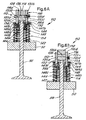
- Valve deactivation system 110 is generally similar to, and operates in a generally similar manner as, valve deactivation system 10. Therefore, only the differences in structure and operation of valve deactivation system 110 relative to valve deactivation system 10 are discussed below.
- Deactivation rocker arm assembly 112 is generally similar to deactivation rocker arm assembly 12, as discussed above, and includes side walls 116a, 116b, first end 116c and second end 116d. Substantially cylindrical pin bores 130a, 130b are defined on opposite sides of second end 116d. Arms 132, 134 are elongate members which, in contrast to arms 32 and arms 34 of deactivation rocker arm assembly 12, extend from opposite sides of the bottom surface (not referenced) of second end 116d of rocker arm 116 for a predetermined distance in a direction toward disk cap 50 and in a manner that is generally parallel with valve stem 38.
- Free motion spring assembly 114 includes outer spring 142, inner spring 144, outer spring retainer 146 and inner spring retainer 148.
- Outer spring 142 is disposed between and in abutting engagement with disk cap 50 and outer spring retainer 142, and surrounds inner spring 144.
- Inner spring 144 is disposed between and in abutting engagement with inner spring retainer 148 and disk cap 50, and surrounds valve stem 38.
- Outer spring 142 and inner spring 144 are substantially concentric relative to each other, with inner spring 144 being disposed between outer spring 142 and valve stem 38.
- Outer spring retainer 146 is a substantially cylindrical collar-like member, and includes collar portion 146a and sleeve portion 146c which extends in a generally perpendicular manner from collar portion 146a. Collar portion 146a defines slots 147a, 147b, through which arms 132, 134 extend to engage inner spring retainer 148. Outer spring 142 abuttingly engages collar portion 146a of outer spring retainer 146. Outer spring retainer 146 engages stem groove 38a of valve stem 38 to thereby couple valve stem 38 and outer spring retainer 146 together. Thus, valve stem 38 and outer spring retainer 146 move as substantially one body. Valve stem 38 extends through sleeve portion 146c.
- Inner spring retainer 148 is a substantially cylindrical collar-like member having a collar portion 148a and sleeve portion 148b. Inner spring retainer 148 is disposed on the outside of and below outer spring retainer 146. More particularly, sleeve portion 148b is disposed outside of sleeve portion 146c of outer spring retainer 146 relative to valve stem 38, and is adjacent to and generally parallel with sleeve portion 146c. Similarly, collar portion 148a is disposed below and adjacent to collar portion 146a of outer spring retainer 146 relative to arms 132, 134. Inner spring 144 abuttingly engages collar portion 148a of inner spring retainer 148.
- center post 118 and rocker arm 116 are coupled together by locking pin assembly 120, and are reciprocated as substantially one body by the cam of engine 26 to thereby reciprocate valve stem 38. More particularly, arms 134a and 134b extend through slots 147a, 147b, respecitvely, of outer spring retainer 146 to engage collar portion 148a of inner spring retainer 148 thereby transferring the reciprocation of deactivation rocker arm 16 to inner spring retainer 146 and compressing inner spring 144.
- outer spring retainer 146 is coupled to valve stem 38 and thus is reciprocated in conjunction therewith. Reciprocation of outer spring retainer 146 compresses outer spring 142.
- valve deactivation system 110 The deactivated or decoupled state of valve deactivation system 110 is shown in Fig. 6B.
- valve deactivation assembly 110 With valve deactivation assembly 110 in the deactivated or decoupled position, rotary motion of the cam of engine 26 is not transferred to pivotal movement of deactivation rocker arm assembly 16 and thus the corresponding valve of internal combustion engine 26 is not reciprocated or actuated. More particularly, rocker arm 16 and center post 18 are no longer coupled together by locking pin assembly 120, and therefore no longer reciprocate as substantially one body. Rather, rocker arm 116 undergoes movement relative to center post 118. Rotary motion of the cam of engine 26 is transferred to reciprocation of rocker arm 116 but is not transferred to reciprocation of center post 118.
Landscapes
- Engineering & Computer Science (AREA)
- Mechanical Engineering (AREA)
- General Engineering & Computer Science (AREA)
- Valve Device For Special Equipments (AREA)
- Valve-Gear Or Valve Arrangements (AREA)
Abstract
Description
Claims (25)
- A valve deactivation system 10, comprising:a deactivation rocker arm assembly 12; anda free motion spring assembly 14.
- The valve deactivation system 10 of claim 1, wherein said deactivation rocker arm assembly 12 comprises:an elongate rocker arm 16, an aperture 28 defined by said rocker arma center post 18 slidingly disposed within said aperture 28, said center post configured for engaging a valve stem of a valve 38 of an internal combustion engine 26; andcoupling means selectively coupling together and decoupling said center post 18 and said rocker arm 16.
- The valve deactivation system 10 of claim 2, wherein said rocker arm 16 includes an end 16D, said aperture 16 being defined by said end.
- The valve deactivation system 10 of claim 2, wherein said end 16D of said rocker arm 16 defines a first pin bore 30a and a second pin bore 30b, said first pin bore and said second pin bore being substantially concentric relative to each other, said center post 18 defining a middle pin bore 36, said coupling means comprises a locking pin assembly 20, said locking pin assembly including an actuating pin 20a, a second pin member 20c and a middle pin member 20b, said actuating pin member 20a slidingly disposed at least partially within said first pin bore 30a, said second pin member 20c slidingly disposed at least partially within said second pin bore 30b, and said middle pin member 20b slidingly disposed at least partially within said middle pin bore 36.
- The valve deactivation system 10 of claim 4, wherein said deactivation rocker arm assembly 12 further comprises a pin spring 20d disposed within said second pin bore 30b, said pin spring 20d normally biasing said locking pin assembly 20 toward a default position wherein said actuator pin 20a member extends a predetermined distance from disposition within said first pin bore 30a in a direction away from said center post 18, said middle pin member 20b extends from disposition within said middle pin bore 36 into said first pin bore 30a, and said second pin member 20c extends from disposition within said second pin bore 30b into said middle pin bore 36 to thereby couple said center post 18 to said rocker arm 16.
- The valve deactivation system 10 of claim 2, wherein said free motion spring assembly 14 comprises:an inner spring retainer 48 surrounding a portion of the valve stem 38;an outer spring retainer 46 surrounding a portion of the valve stem 38;an inner spring 44 surrounding a portion of the valve stem 38, said inner spring being disposed between a disk cap 50 associated with the valve stem 38 and said inner spring retainer 48; andan outer spring 42 surrounding said inner spring 44, said outer spring 42 being disposed between said outer spring retainer 46 and the disk cap 50.
- The valve deactivation system 10, 110 of claim 6, wherein said rocker arm 16, 116 includes elongate arms 32,34; 132,134, said arms being one of attached to and integral with said body of said rocker arm 16, 116 and extending therefrom, said arms 32, 34, 132, 134 engaging one of said inner spring retainer 148 and said outer spring retainer 46.
- The valve deactivation system 10 of claim 7, wherein said arms 32, 34 extend in a direction that is generally parallel with said body of said rocker arm 16, said outer spring 42 biasing said outer spring retainer 46 into engagement with said arms 32, 34, said inner spring retainer 48 configured for being coupled to the valve stem 38.
- The valve deactivation system 10 of claim 8, wherein said outer spring retainer 46 includes a rim 46b, said outer spring 42 normally biasing said rim 46b into engagement with a periphery 48a of said inner spring retainer 48.
- The valve deactivation system 110 of claim 7, wherein said outer spring retainer 146 includes slots 147a, 147b, each of said slots corresponding to a respective one of said arms 132, 134, said arms extending in a direction generally perpendicular to said body of said rocker arm 116, each of said arms extending through a respective one of said slots 147a, 147b, said inner spring 144 biasing said inner spring retainer 198 into engagement with said arms 132,134, said outer spring retainer 146 configured for being coupled to the valve stem 38.
- The valve deactivation system 10 of claim 9, wherein said inner spring retainer 148 is disposed below said outer spring retainer 146 relative to said rocker arm 116, said inner spring 144 normally biasing said inner spring; retainer 148 into engagement with said outer spring retainer 146.
- A deactivation rocker arm assembly 12, comprising:an elongate rocker arm 16 having an end 16d, an aperture 28 defined by said end;a center post 18 slidingly disposed within said aperture 28, said center post 18 configured for engaging a valve stem 38 of a valve of an internal combustion engine 26; andcoupling means selectively coupling together and decoupling said center post 18 and said rocker arm 16.
- The deactivation rocker arm assembly 112 of claim 12, wherein said end 116d of said rocker arm 116 defines a first pin bore 130a and a second pin bore 130b, said first pin bore 130a and said second pin bore 130b being substantially concentric relative to each other, said center post 118 defining a middle pin bore 136, said coupling means comprises a locking pin assembly 120, said locking pin assembly 120 including an actuating pin 20a, a second pin member 20c and a middle pin member 20b, said actuating pin 20a member slidingly disposed at least partially within said first pin bore 30a, said second pin member 20b slidingly disposed at least partially within said second pin bore130b, and said middle pin member slidingly disposed at least partially within said middle pin bore 36.
- The deactivation rocker arm assembly 112 of claim 13, further comprising a pin spring 20d disposed within said second pin bore 130b, said pin spring 20d normally biasing said locking pin assembly 120 toward a default position wherein said actuator pin member 20a extends a predetermined distance from disposition within said first pin bore 130a in a direction away from said center post 118, said middle pin member 20b extends from disposition within said middle pin bore 36 into said first pin bore 130a, and said second pin member 20c extends from disposition within said second pin bore 130b into said middle pin bore 36 to thereby couple said center post to said rocker arm 116.
- The deactivation rocker arm 12, 112 assembly of claim 12, wherein said rocker arm 16, 116 includes elongate arms 32, 34, 132, 134, said arms being one of attached to and integral with said body of said rocker arm 16, 116 and extending therefrom.
- The deactivation rocker arm 12 assembly of claim 15, wherein said arms 32, 34 132,134 extend from said end 16d, 116d of said rocker arm 16,116 in a manner that is generally parallel with said rocker arm 16, 116.
- The deactivation rocker arm 112 assembly of claim 15, wherein said arms 132, 134 extend from said end 116d of said rocker arm 116 in a manner that is generally perpendicular with said rocker arm 116.
- The deactivation rocker arm assembly of claim 12, 112 wherein said rocker arm 16, 116 defines a roller orifice 22, a roller 24 being disposed within said roller orifice 22 and being coupled to said rocker arm 16, 116, said roller 24 configured for engaging a cam of the internal combustion engine 26.
- A free motion spring assembly 14,114, comprising:an inner spring retainer 48,148 surrounding a portion of a valve stem 38 of a valve of an internal combustion engine 26;an outer spring retainer 46,146 surrounding a portion of the valve stem 38;an inner spring 44, 144 surrounding a portion of the valve stem 38, said inner spring being disposed between a disk cap 50 associated with the valve stem 38 and said spring retainer 48, 148; andan outer spring 42,142 surrounding the inner spring 44,144, said outer spring 42,142 being disposed between said outer spring retainer 46,146 and the disk cap 50.
- The free motion spring assembly 14,114 of claim 19, wherein one of said outer spring retainer 46,146 and said inner spring retainer 44, 144 is configured for being coupled to the valve stem 38.
- The free motion spring assembly 14 of claim 19, wherein said outer spring retainer 46 includes a rim 46b, said outer spring 42 normally biasing said rim 46b into engagement with a periphery 48a of said inner spring retainer 48, said inner spring 44 configured for engaging the valve stem 38.
- The free motion spring assembly 114 of claim 19, wherein said outer spring retainer 146 includes slots 147a, 147b, said inner spring retainer 148 being disposed below said outer spring retainer 146 relative a rocker arm, said outer spring retainer 146 configured for being coupled to the valve stem 38.
- An internal combustion engine 26, comprising:an elongate rocker arm 116, an aperture 28 defined by said rocker arm 16;a center post 18 slidingly disposed within said aperture 28, said center post 18 engaging a valve stem 28 of a valve of said internal combustion engine 26; andcoupling means selectively coupling together and decoupling said center post 18 and said rocker arm 16.
- The internal combustion engine 26 of claim 23, further comprising a free motion spring assembly 14, 114, said free motion spring assembly including:an inner spring retainer 48, 148 surrounding a portion of said valve stem 38;an outer spring retainer 46, 146 surrounding a portion of said valve stem 38;an inner spring 44, 144 surrounding a portion of said valve stem 38, said inner spring being disposed between said inner spring retainer 48, 148 and a disk cap 50 of said internal combustion engine 26, said disk cap being associated with said valve stem 38; andan outer spring 42, 142 surrounding said inner spring 44, 144, said outer spring 42, 142 being disposed between said outer spring retainer 46, 146 and said disk cap 50.
- The internal combustion engine 26 of claim 24, wherein one of said inner spring retainer 48, 148 and said outer spring retainer 46, 146 is coupled to said valve stem 38.
Applications Claiming Priority (2)
| Application Number | Priority Date | Filing Date | Title |
|---|---|---|---|
| US755290 | 2001-01-05 | ||
| US09/755,290 US6799543B2 (en) | 2001-01-05 | 2001-01-05 | Valve deactivation system with free motion spring |
Publications (3)
| Publication Number | Publication Date |
|---|---|
| EP1221541A2 true EP1221541A2 (en) | 2002-07-10 |
| EP1221541A3 EP1221541A3 (en) | 2004-07-21 |
| EP1221541B1 EP1221541B1 (en) | 2007-03-14 |
Family
ID=25038534
Family Applications (1)
| Application Number | Title | Priority Date | Filing Date |
|---|---|---|---|
| EP01204981A Expired - Lifetime EP1221541B1 (en) | 2001-01-05 | 2001-12-18 | Valve deactivation system |
Country Status (3)
| Country | Link |
|---|---|
| US (2) | US6799543B2 (en) |
| EP (1) | EP1221541B1 (en) |
| DE (1) | DE60127230T2 (en) |
Cited By (2)
| Publication number | Priority date | Publication date | Assignee | Title |
|---|---|---|---|---|
| DE102007013947A1 (en) * | 2007-03-23 | 2008-09-25 | Schaeffler Kg | Valve gear of an internal combustion engine with a deactivatable Tellerhubventil |
| EP2492460A3 (en) * | 2011-02-22 | 2013-01-23 | Suzuki Motor Corporation | Valve train device and cylinder head provided with same |
Families Citing this family (2)
| Publication number | Priority date | Publication date | Assignee | Title |
|---|---|---|---|---|
| JP3673201B2 (en) * | 2001-09-14 | 2005-07-20 | 本田技研工業株式会社 | Motor control device for deceleration cylinder-removed engine vehicle |
| US20050188930A1 (en) * | 2004-02-18 | 2005-09-01 | Best Richard R. | Valve deactivation device |
Family Cites Families (16)
| Publication number | Priority date | Publication date | Assignee | Title |
|---|---|---|---|---|
| DE3239941A1 (en) | 1982-10-28 | 1984-05-03 | Volkswagenwerk Ag, 3180 Wolfsburg | Device for switching off the valve mechanism of an internal combustion engine |
| US5020488A (en) * | 1989-11-22 | 1991-06-04 | Fuji Jukogyo Kabushiki Kaisha | Valve mechanism for an internal combustion engine |
| US4986227A (en) * | 1990-05-08 | 1991-01-22 | Dewey Iii Albert B | Variable lift valve train |
| US5239952A (en) * | 1991-11-08 | 1993-08-31 | Atsugi Unisia Corporation | Valve actuating apparatus |
| DE4334995C2 (en) * | 1993-10-14 | 1996-01-11 | Audi Ag | Valve train for a multi-cylinder internal combustion engine |
| US5544628A (en) * | 1994-07-06 | 1996-08-13 | Volkswagen Ag | Valve control arrangement for an internal combustion engine |
| SE504145C2 (en) * | 1995-03-20 | 1996-11-18 | Volvo Ab | Exhaust valve mechanism in an internal combustion engine |
| US6125828A (en) * | 1995-08-08 | 2000-10-03 | Diesel Engine Retarders, Inc. | Internal combustion engine with combined cam and electro-hydraulic engine valve control |
| US5584267A (en) * | 1995-12-20 | 1996-12-17 | Eaton Corporation | Latchable rocker arm mounting |
| DE19608651A1 (en) * | 1996-03-06 | 1997-09-11 | Schaeffler Waelzlager Kg | Valve train for gas exchange valves of internal combustion engines |
| US5908015A (en) | 1996-07-06 | 1999-06-01 | Meta Motoren- Und Energie Technik Gmbh | Arrangement for interrupting the flow of force between a camshaft and a valve |
| US5709180A (en) | 1997-02-06 | 1998-01-20 | General Motors Corporation | Narrow cam two-step lifter |
| DE19744253A1 (en) | 1997-10-07 | 1999-04-08 | Schaeffler Waelzlager Ohg | Motor valve push rod to operate the valves in an internal combustion motor |
| JPH11343821A (en) | 1998-05-29 | 1999-12-14 | Aisin Seiki Co Ltd | Variable valve gear |
| JP4067662B2 (en) | 1998-09-14 | 2008-03-26 | 本田技研工業株式会社 | Internal combustion engine valve device having valve deactivation mechanism |
| DE19914046A1 (en) | 1999-03-27 | 2000-09-28 | Schaeffler Waelzlager Ohg | Valve drive tappet for internal combustion engine, with compression piston at leased partly enclosed by spring on region projecting from underside of tappet |
-
2001
- 2001-01-05 US US09/755,290 patent/US6799543B2/en not_active Expired - Fee Related
- 2001-12-18 EP EP01204981A patent/EP1221541B1/en not_active Expired - Lifetime
- 2001-12-18 DE DE60127230T patent/DE60127230T2/en not_active Expired - Fee Related
-
2004
- 2004-09-28 US US10/951,980 patent/US20050039712A1/en not_active Abandoned
Cited By (4)
| Publication number | Priority date | Publication date | Assignee | Title |
|---|---|---|---|---|
| DE102007013947A1 (en) * | 2007-03-23 | 2008-09-25 | Schaeffler Kg | Valve gear of an internal combustion engine with a deactivatable Tellerhubventil |
| WO2008116704A1 (en) * | 2007-03-23 | 2008-10-02 | Schaeffler Kg | Valve drive of an internal combustion engine, comprising a reciprocating poppet valve that can be deactivated |
| EP2492460A3 (en) * | 2011-02-22 | 2013-01-23 | Suzuki Motor Corporation | Valve train device and cylinder head provided with same |
| US8936001B2 (en) | 2011-02-22 | 2015-01-20 | Suzuki Motor Corporation | Valve train device and cylinder head provided with same |
Also Published As
| Publication number | Publication date |
|---|---|
| DE60127230T2 (en) | 2007-11-22 |
| US20050039712A1 (en) | 2005-02-24 |
| EP1221541A3 (en) | 2004-07-21 |
| DE60127230D1 (en) | 2007-04-26 |
| EP1221541B1 (en) | 2007-03-14 |
| US20020088414A1 (en) | 2002-07-11 |
| US6799543B2 (en) | 2004-10-05 |
Similar Documents
| Publication | Publication Date | Title |
|---|---|---|
| US6325030B1 (en) | Roller finger follower for valve deactivation | |
| JP5108508B2 (en) | Main and offset actuators, rocker arms for engine valve actuation | |
| EP2137386B1 (en) | Engine brake having an articulate rocker arm and a rocker shaft mounted housing | |
| US8910606B2 (en) | Positive control (desmodromic) valve systems for internal combustion engines | |
| JP4541733B2 (en) | 2-stage valve lift and valve deactivation | |
| EP3169880B1 (en) | Pushrod assembly | |
| US20080202455A1 (en) | Internal Combustion Engine With Gas Exchange Valve Deactivation | |
| CN113669124A (en) | Rocker device for valve train of internal combustion engine | |
| EP3762588A1 (en) | Rocker arm control systems | |
| EP1221541B1 (en) | Valve deactivation system | |
| CN100425818C (en) | Vibration control arrangement for internal combustion engines | |
| US6481398B2 (en) | High-low speed range switching type valve mechanism for internal combustion engine | |
| US6382173B1 (en) | Split body deactivation valve lifter | |
| CN120946435A (en) | Engine valve deactivation system with switchable rocker arm cam lift | |
| US10871087B2 (en) | Switchable rocker arm | |
| JP4191538B2 (en) | Engine valve gear | |
| US6964252B2 (en) | Valve lifter for internal combustion engine | |
| US20090013967A1 (en) | Spring-less valve train for internal combustion engine | |
| WO2015020678A1 (en) | Helical torsion valve spring assembly | |
| JPS6316113A (en) | Tappet mechanism with valve stroke holding device for internal combustion engine | |
| JPS5879638A (en) | Valve driving device provided with idle function | |
| KR19980029097A (en) | Connecting rod connection structure |
Legal Events
| Date | Code | Title | Description |
|---|---|---|---|
| PUAI | Public reference made under article 153(3) epc to a published international application that has entered the european phase |
Free format text: ORIGINAL CODE: 0009012 |
|
| AK | Designated contracting states |
Kind code of ref document: A2 Designated state(s): AT BE CH CY DE DK ES FI FR GB GR IE IT LI LU MC NL PT SE TR |
|
| AX | Request for extension of the european patent |
Free format text: AL;LT;LV;MK;RO;SI |
|
| PUAL | Search report despatched |
Free format text: ORIGINAL CODE: 0009013 |
|
| AK | Designated contracting states |
Kind code of ref document: A3 Designated state(s): AT BE CH CY DE DK ES FI FR GB GR IE IT LI LU MC NL PT SE TR |
|
| AX | Request for extension of the european patent |
Extension state: AL LT LV MK RO SI |
|
| 17P | Request for examination filed |
Effective date: 20050121 |
|
| AKX | Designation fees paid |
Designated state(s): DE FR GB |
|
| 17Q | First examination report despatched |
Effective date: 20050628 |
|
| GRAP | Despatch of communication of intention to grant a patent |
Free format text: ORIGINAL CODE: EPIDOSNIGR1 |
|
| GRAS | Grant fee paid |
Free format text: ORIGINAL CODE: EPIDOSNIGR3 |
|
| GRAA | (expected) grant |
Free format text: ORIGINAL CODE: 0009210 |
|
| AK | Designated contracting states |
Kind code of ref document: B1 Designated state(s): DE FR GB |
|
| REG | Reference to a national code |
Ref country code: GB Ref legal event code: FG4D |
|
| REF | Corresponds to: |
Ref document number: 60127230 Country of ref document: DE Date of ref document: 20070426 Kind code of ref document: P |
|
| ET | Fr: translation filed | ||
| PLBE | No opposition filed within time limit |
Free format text: ORIGINAL CODE: 0009261 |
|
| STAA | Information on the status of an ep patent application or granted ep patent |
Free format text: STATUS: NO OPPOSITION FILED WITHIN TIME LIMIT |
|
| 26N | No opposition filed |
Effective date: 20071217 |
|
| PGFP | Annual fee paid to national office [announced via postgrant information from national office to epo] |
Ref country code: FR Payment date: 20070425 Year of fee payment: 6 |
|
| PGFP | Annual fee paid to national office [announced via postgrant information from national office to epo] |
Ref country code: DE Payment date: 20071213 Year of fee payment: 7 |
|
| GBPC | Gb: european patent ceased through non-payment of renewal fee |
Effective date: 20071218 |
|
| REG | Reference to a national code |
Ref country code: FR Ref legal event code: ST Effective date: 20081020 |
|
| PG25 | Lapsed in a contracting state [announced via postgrant information from national office to epo] |
Ref country code: GB Free format text: LAPSE BECAUSE OF NON-PAYMENT OF DUE FEES Effective date: 20071218 |
|
| PG25 | Lapsed in a contracting state [announced via postgrant information from national office to epo] |
Ref country code: FR Free format text: LAPSE BECAUSE OF NON-PAYMENT OF DUE FEES Effective date: 20071231 |
|
| PG25 | Lapsed in a contracting state [announced via postgrant information from national office to epo] |
Ref country code: DE Free format text: LAPSE BECAUSE OF NON-PAYMENT OF DUE FEES Effective date: 20090701 |