EP1221537A2 - Method and apparatus for reducing turbine blade tip temperatures - Google Patents
Method and apparatus for reducing turbine blade tip temperatures Download PDFInfo
- Publication number
- EP1221537A2 EP1221537A2 EP02250143A EP02250143A EP1221537A2 EP 1221537 A2 EP1221537 A2 EP 1221537A2 EP 02250143 A EP02250143 A EP 02250143A EP 02250143 A EP02250143 A EP 02250143A EP 1221537 A2 EP1221537 A2 EP 1221537A2
- Authority
- EP
- European Patent Office
- Prior art keywords
- tip
- wall
- airfoil
- rotor blade
- side wall
- Prior art date
- Legal status (The legal status is an assumption and is not a legal conclusion. Google has not performed a legal analysis and makes no representation as to the accuracy of the status listed.)
- Granted
Links
Images


Classifications
-
- F—MECHANICAL ENGINEERING; LIGHTING; HEATING; WEAPONS; BLASTING
- F01—MACHINES OR ENGINES IN GENERAL; ENGINE PLANTS IN GENERAL; STEAM ENGINES
- F01D—NON-POSITIVE DISPLACEMENT MACHINES OR ENGINES, e.g. STEAM TURBINES
- F01D5/00—Blades; Blade-carrying members; Heating, heat-insulating, cooling or antivibration means on the blades or the members
- F01D5/12—Blades
- F01D5/14—Form or construction
- F01D5/20—Specially-shaped blade tips to seal space between tips and stator
-
- F—MECHANICAL ENGINEERING; LIGHTING; HEATING; WEAPONS; BLASTING
- F01—MACHINES OR ENGINES IN GENERAL; ENGINE PLANTS IN GENERAL; STEAM ENGINES
- F01D—NON-POSITIVE DISPLACEMENT MACHINES OR ENGINES, e.g. STEAM TURBINES
- F01D5/00—Blades; Blade-carrying members; Heating, heat-insulating, cooling or antivibration means on the blades or the members
- F01D5/12—Blades
- F01D5/14—Form or construction
- F01D5/18—Hollow blades, i.e. blades with cooling or heating channels or cavities; Heating, heat-insulating or cooling means on blades
- F01D5/186—Film cooling
-
- F—MECHANICAL ENGINEERING; LIGHTING; HEATING; WEAPONS; BLASTING
- F05—INDEXING SCHEMES RELATING TO ENGINES OR PUMPS IN VARIOUS SUBCLASSES OF CLASSES F01-F04
- F05D—INDEXING SCHEME FOR ASPECTS RELATING TO NON-POSITIVE-DISPLACEMENT MACHINES OR ENGINES, GAS-TURBINES OR JET-PROPULSION PLANTS
- F05D2240/00—Components
- F05D2240/10—Stators
- F05D2240/12—Fluid guiding means, e.g. vanes
- F05D2240/121—Fluid guiding means, e.g. vanes related to the leading edge of a stator vane
-
- F—MECHANICAL ENGINEERING; LIGHTING; HEATING; WEAPONS; BLASTING
- F05—INDEXING SCHEMES RELATING TO ENGINES OR PUMPS IN VARIOUS SUBCLASSES OF CLASSES F01-F04
- F05D—INDEXING SCHEME FOR ASPECTS RELATING TO NON-POSITIVE-DISPLACEMENT MACHINES OR ENGINES, GAS-TURBINES OR JET-PROPULSION PLANTS
- F05D2240/00—Components
- F05D2240/20—Rotors
- F05D2240/30—Characteristics of rotor blades, i.e. of any element transforming dynamic fluid energy to or from rotational energy and being attached to a rotor
- F05D2240/303—Characteristics of rotor blades, i.e. of any element transforming dynamic fluid energy to or from rotational energy and being attached to a rotor related to the leading edge of a rotor blade
-
- F—MECHANICAL ENGINEERING; LIGHTING; HEATING; WEAPONS; BLASTING
- F05—INDEXING SCHEMES RELATING TO ENGINES OR PUMPS IN VARIOUS SUBCLASSES OF CLASSES F01-F04
- F05D—INDEXING SCHEME FOR ASPECTS RELATING TO NON-POSITIVE-DISPLACEMENT MACHINES OR ENGINES, GAS-TURBINES OR JET-PROPULSION PLANTS
- F05D2250/00—Geometry
- F05D2250/70—Shape
-
- F—MECHANICAL ENGINEERING; LIGHTING; HEATING; WEAPONS; BLASTING
- F05—INDEXING SCHEMES RELATING TO ENGINES OR PUMPS IN VARIOUS SUBCLASSES OF CLASSES F01-F04
- F05D—INDEXING SCHEME FOR ASPECTS RELATING TO NON-POSITIVE-DISPLACEMENT MACHINES OR ENGINES, GAS-TURBINES OR JET-PROPULSION PLANTS
- F05D2260/00—Function
- F05D2260/20—Heat transfer, e.g. cooling
- F05D2260/202—Heat transfer, e.g. cooling by film cooling
Definitions
- This application relates generally to gas turbine engine rotor blades and, more particularly, to methods and apparatus for reducing rotor blade tip temperatures.
- Gas turbine engine rotor blades typically include airfoils having leading and trailing edges, a pressure side, and a suction side.
- the pressure and suction sides connect at the airfoil leading and trailing edges, and span radially between the airfoil root and the tip.
- the airfoils include a tip region that extends radially outward from the airfoil tip.
- the airfoil tip regions include a first tip wall extending from the airfoil leading edge to the trailing edge, and a second tip wall also extending from the airfoil leading edge to connect with the first tip wall at the airfoil trailing edge.
- the tip region prevents damage to the airfoil if the rotor blade rubs against the stator components.
- At least some known rotor blades include slots within the tip walls to permit combustion gases at a lower temperature to flow through the tip regions.
- At least some known rotor blades include a shelf adjacent the tip region to facilitate reducing operating temperatures of the tip regions.
- the shelf is defined within the pressure side of the airfoil and disrupt combustion gas flow as the rotor blades rotate, thus enabling a film layer of cooling air to form against the pressure side of the airfoil.
- the film layer insulates the blade from the higher temperature combustion gases.
- a rotor blade for a gas turbine engine includes a tip region that facilitates reducing operating temperatures of the rotor blade, without sacrificing aerodynamic efficiency of the turbine engine.
- the tip region includes a first tip wall and a second tip wall that extend radially outward from an airfoil tip plate.
- the first tip wall extends from adjacent a leading edge of the airfoil to a trailing edge of the airfoil.
- the second tip wall also extends from adjacent the airfoil leading edge and connects with the first tip wall at the airfoil trailing edge to define an open-top tip cavity. At least a portion of the second tip wall is recessed to define a tip shelf.
- a notch extends from the tip plate and is defined between the first and second tip walls at the airfoil leading edge. The notch is in flow communication with the tip cavity.
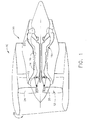
- FIG. 1 is a schematic illustration of a gas turbine engine 10 including a fan assembly 12, a high pressure compressor 14, and a combustor 16.
- Engine 10 also includes a high pressure turbine 18, a low pressure turbine 20, and a booster 22.
- Fan assembly 12 includes an array of fan blades 24 extending radially outward from a rotor disc 26.
- Engine 10 has an intake side 28 and an exhaust side 30.
- Airflow (not shown in Figure 1) from combustor 16 drives turbines 18 and 20, and turbine 20 drives fan assembly 12.
- FIG 2 is a partial perspective view of a rotor blade 40 that may be used with a gas turbine engine, such as gas turbine engine 10 (shown in Figure 1).
- a gas turbine engine such as gas turbine engine 10 (shown in Figure 1).
- a plurality of rotor blades 40 form a high pressure turbine rotor blade stage (not shown) of gas turbine engine 10.
- Each rotor blade 40 includes a hollow airfoil 42 and an integral dovetail (not shown) used for mounting airfoil 42 to a rotor disk (not shown) in a known manner.
- Airfoil 42 includes a first side wall 44 and a second side wall 46.
- First side wall 44 is convex and defines a suction side of airfoil 42
- second side wall 46 is concave and defines a pressure side of airfoil 42.
- Side walls 44 and 46 are joined at a leading edge 48 and at an axially-spaced trailing edge 50 of airfoil 42 that is downstream from leading edge 48.
- First and second side walls 44 and 46 extend longitudinally or radially outward to span from a blade root (not shown) positioned adjacent the dovetail to a tip plate 54 which defines a radially outer boundary of an internal cooling chamber (not shown).
- the cooling chamber is defined within airfoil 42 between side walls 44 and 46.
- Internal cooling of airfoils 42 is known in the art.
- the cooling chamber includes a serpentine passage cooled with compressor bleed air.
- side walls 44 and 46 include a plurality of film cooling openings (not shown), extending therethrough to facilitate additional cooling of the cooling chamber.
- airfoil 42 includes a plurality of trailing edge openings (not shown) used to discharge cooling air from the cooling chamber.
- a tip region 60 of airfoil 42 is sometimes known as a squealer tip, and includes a first tip wall 62 and a second tip wall 64 formed integrally with airfoil 42.
- First tip wall 62 extends from adjacent airfoil leading edge 48 along airfoil first side wall 44 to airfoil trailing edge 50. More specifically, first tip wall 62 extends from tip plate 54 to an outer edge 65 for a height 66.
- First tip wall height 66 is substantially constant along first tip wall 62.
- Second tip wall 64 extends from adjacent airfoil leading edge 48 along second side wall 46 to connect with first tip wall 62 at airfoil trailing edge 50. More specifically, second tip wall 64 is laterally spaced from first tip wall 62 such that an open-top tip cavity 70 is defined with tip walls 62 and 64, and tip plate 54. Second tip wall 64 also extends radially outward from tip plate 54 to an outer edge 72 for a height 74. In the exemplary embodiment, second tip wall height 74 is equal first tip wall height 66. Alternatively, second tip wall height 74 is not equal first tip wall height 66.
- a notch 80 is defined between first tip wall 62 and second tip wall 64 along airfoil leading edge 48. More specifically, notch 80 has a width 82 extending between first and second tip walls 62 and 64, and a height 84 measured between a bottom 86 of notch 80 defined by tip plate 54, and first and second tip wall outer edges 65 and 72, respectively.
- notch 80 does not extend from tip plate 54, but instead extends from first and second tip wall outer edges 65 and 72, respectively, towards tip plate 54 for a distance (not shown) that is less than notch height 84, and accordingly, notch bottom 86 is a distance (not shown) from tip plate 54.
- second tip wall 64 is not connected to first tip wall 62 at airfoil trailing edge 50, and an opening (not shown) is defined between first tip wall 62 and second tip wall 64 at airfoil trailing edge 50.
- Notch 80 is in flow communication with open-top tip cavity 70 and permits combustion gas at a lower temperature to enter cavity 70 for lower heating purposes.
- notch 80 also includes a guide wall (not shown in Figure 2) used to channel flow entering open-top tip cavity 70 towards second tip wall 64. More specifically, the guide wall extends from notch 80 towards airfoil trailing edge 50.
- Second tip wall 64 is recessed at least in part from airfoil second side wall 46. More specifically, second tip wall 64 is recessed from airfoil second side wall 46 toward first tip wall 62 to define a radially outwardly facing first tip shelf 90 which extends generally between airfoil leading and trailing edges 48 and 50. More specifically, shelf 90 includes a front edge 94 and an aft edge 96. Front edge 94 and aft edge 96 each taper to be flush with second side wall 46. Shelf front edge 94 is a distance 98 downstream of airfoil leading edge 48, and shelf aft edge 96 is a distance 100 upstream from airfoil trailing edge 50.
- tip plate 54 is generally imperforate and only includes a plurality of openings 106 extending through tip plate 54 at tip shelf 90. Openings 106 are spaced axially along shelf 90 and are in flow communication between trough 102 and the internal airfoil cooling chamber.
- tip region 60 and airfoil 42 are coated with a thermal barrier coating.
- squealer tip walls 62 and 64 are positioned in close proximity with a conventional stationary stator shroud (not shown), and define a tight clearance (not shown) therebetween that facilitates reducing combustion gas leakage therethrough.
- Tip walls 62 and 64 extend radially outward from airfoil 42. Accordingly, if rubbing occurs between rotor blades 40 and the stator shroud, only tip walls 62 and 64 contact the shroud and airfoil 42 remains intact.
- combustion gases near turbine blade tip region leading edge 48 are at a lower temperature than gases near turbine blade tip region trailing edge 50.
- notch 80 a heat load of tip region 60 is reduced. More specifically, combustion gases flowing into notch 80 are at a higher pressure and reduced temperature than gases leaking from rotor blade pressure side 46 through the tip clearance to rotor blade suction side 44. As a result, notch 80 facilitates reducing an operating temperatures within tip region 60.
- trough 102 provides a discontinuity in airfoil pressure side 46 which causes the combustion gases to separate from airfoil second side wall 46, thus facilitating a decrease in heat transfer thereof. Additionally, trough 102 provides a region for cooling air to accumulate and form a film against side wall 46.
- First tip shelf openings 106 discharge cooling air from the airfoil internal cooling chamber to form a film cooling layer on tip region 60. Because of blade rotation, combustion gases outside rotor blade 40 at leading edge 48 near a blade pitch line (not shown) will migrate in a radial flow toward airfoil tip region 60 near trailing edge 50 along second side wall 46 such that leading edge tip operating temperatures are lower than trailing edge tip operating temperatures.
- First tip shelf 90 functions as a backward facing step in the migrated radial flow and provides a shield for the film of cooling air accumulated against side wall 46. As a result, shelf 90 facilitates improving cooling effectiveness of the film to lower operating temperatures of side wall 46.
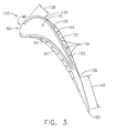
- FIG 3 is a cross-sectional view of an alternative embodiment of a rotor blade 120 that may be used with a gas turbine engine, such as gas turbine engine 10 (shown in Figure 1).
- Rotor blade 120 is substantially similar to rotor blade 40 shown in Figure 2, and components in rotor blade 120 that are identical to components of rotor blade 40 are identified in Figure 3 using the same reference numerals used in Figure 2.
- rotor blade 120 includes airfoil 42 (shown in Figure 2), side walls 44 and 46 (shown in Figure 2) extending between leading and trailing edges 48 and 50, respectively, and notch 80.
- rotor blade 120 includes second tip wall 64 and first tip shelf 90.
- rotor blade 120 includes a first tip wall 122. Notch 80 is defined between first and second tip walls 122 and 64, respectively.
- First tip wall 122 extends from adjacent airfoil leading edge 48 along first side wall 44 to connect with second tip wall 64 at airfoil trailing edge 50. More specifically, first tip wall 122 is laterally spaced from second tip wall 64 to define open-top tip cavity 70. First tip wall 122 also extends a height (not shown) radially outward from tip plate 54 to an outer edge 126. In the exemplary embodiment, the first tip wall height is equal second tip wall height 74. Alternatively, the first tip wall height is not equal second tip wall height 74.
- First tip wall 122 is recessed at least in part from airfoil first side wall 44. More specifically, first tip wall 122 is recessed from airfoil first side wall 44 toward second tip wall 64 to define a radially outwardly facing second tip shelf 130 which extends generally between airfoil leading and trailing edges 48 and 50. More specifically, shelf 130 includes a front edge 134 and an aft edge 136. Front edge 134 and aft edge 136 each taper to be flush with first side wall 44. Shelf front edge 134 is a distance 138 downstream of airfoil leading edge 48, and shelf aft edge 136 is a distance 140 upstream from airfoil trailing edge 50.
- tip plate 54 is generally imperforate and includes plurality of openings 106 extending through tip plate 54 at first tip shelf 90, and a plurality of openings 146 extending through tip plate 54 at second tip shelf 130. Openings 146 are spaced axially along second tip shelf 130 and are in flow communication between trough 144 and the internal airfoil cooling chamber.
- tip region 62 and airfoil 42 are coated with a thermal barrier coating.
- squealer tip walls 122 and 64 are positioned in close proximity with a conventional stationary stator shroud (not shown), and define a tight clearance (not shown) therebetween to facilitate reducing combustion gas leakage therethrough.
- Tip wall 122 functions in an identical manner as tip wall 62 described above, and extends radially outward from airfoil 42. Accordingly, if rubbing occurs between rotor blades 40 and the stator shroud, only tip walls 122 and 64 contact the shroud and airfoil 42 remains intact.
- troughs 102 and 144 respectively provide a discontinuity in airfoil pressure side 46 and airfoil suction side 44, respectively, which causes the combustion gases to separate from airfoil side walls 46 and 44, respectively, thus facilitating a decrease in heat transfer thereof.
- Trough 144 functions similarly with trough 102 to facilitate film cooling circulation.
- FIG 4 is a partial perspective view of an alternative embodiment of a rotor blade 200 that may be used with a gas turbine engine, such as gas turbine engine 10 (shown in Figure 1).
- Rotor blade 200 is substantially similar to rotor blade 40 shown in Figure 2, and components in rotor blade 200 that are identical to components of rotor blade 40 are identified in Figure 4 using the same reference numerals used in Figure 2.
- rotor blade 200 includes airfoil 42, side walls 44 and 46 extending between leading and trailing edges 48 and 50, respectively, and notch 80.
- rotor blade 200 includes first tip wall 62, notch 80, and a second tip wall 202. Notch 80 is defined between first and second tip walls 62 and 202, respectively.
- Second tip wall 202 extends from adjacent airfoil leading edge 48 along airfoil first side wall 44 to airfoil trailing edge 50. More specifically, second tip wall 202 extends from tip plate 54 to an outer edge 204 for a height (not shown). The second tip wall height is substantially constant along second tip wall 202. Second tip wall 202 is laterally spaced from first tip wall 62 to define open-top tip cavity 70 In the exemplary embodiment, the second tip wall height is equal first tip wall height 66. Alternatively, the second tip wall height is not equal first tip wall height 66.
- Notch 80 includes a guide wall 210 extending from first tip wall 62 towards airfoil trailing edge. More specifically, guide wall 210 curves to extend from first tip wall 62 to define a curved entrance 212 for notch 80. Guide wall 210 has a length 214 that is selected to channel airflow entering open-top tip cavity 70 towards second tip wall 202.
- the above-described rotor blade is cost-effective and highly reliable.
- the rotor blade includes a leading edge notch defined between leading edges of first and second tip walls.
- the tip walls connect at a trailing edge of the rotor blade and define a tip cavity.
- one of the tip walls is recessed to define a tip shelf.
- the tip walls prevent the rotor blade from rubbing against stationary structural members.
- the rotor blade notch facilitates lowering heating of the tip cavity without increasing cooling air requirements and sacrificing aerodynamic efficiency of the rotor blade.
- the tip shelf disrupts combustion gases flowing past the airfoil to facilitate a cooling layer being formed against the shelf. As a result, cooler operating temperatures within the rotor blade facilitate extending a useful life of the rotor blades in a cost-effective and reliable manner.
Abstract
Description
- This application relates generally to gas turbine engine rotor blades and, more particularly, to methods and apparatus for reducing rotor blade tip temperatures.
- Gas turbine engine rotor blades typically include airfoils having leading and trailing edges, a pressure side, and a suction side. The pressure and suction sides connect at the airfoil leading and trailing edges, and span radially between the airfoil root and the tip. To facilitate reducing combustion gas leakage between the airfoil tips and stationary stator components, the airfoils include a tip region that extends radially outward from the airfoil tip.
- The airfoil tip regions include a first tip wall extending from the airfoil leading edge to the trailing edge, and a second tip wall also extending from the airfoil leading edge to connect with the first tip wall at the airfoil trailing edge. The tip region prevents damage to the airfoil if the rotor blade rubs against the stator components.
- During operation, combustion gases impacting the rotating rotor blades transfer heat into the blade airfoils and tip regions. Over time, continued operation in higher temperatures may cause the airfoil tip regions to thermally fatigue. To facilitate reducing operating temperatures of the airfoil tip regions, at least some known rotor blades include slots within the tip walls to permit combustion gases at a lower temperature to flow through the tip regions.
- To facilitate minimizing thermal fatigue to the rotor blade tips, at least some known rotor blades include a shelf adjacent the tip region to facilitate reducing operating temperatures of the tip regions. The shelf is defined within the pressure side of the airfoil and disrupt combustion gas flow as the rotor blades rotate, thus enabling a film layer of cooling air to form against the pressure side of the airfoil. The film layer insulates the blade from the higher temperature combustion gases.
- In an exemplary embodiment, a rotor blade for a gas turbine engine includes a tip region that facilitates reducing operating temperatures of the rotor blade, without sacrificing aerodynamic efficiency of the turbine engine. The tip region includes a first tip wall and a second tip wall that extend radially outward from an airfoil tip plate. The first tip wall extends from adjacent a leading edge of the airfoil to a trailing edge of the airfoil. The second tip wall also extends from adjacent the airfoil leading edge and connects with the first tip wall at the airfoil trailing edge to define an open-top tip cavity. At least a portion of the second tip wall is recessed to define a tip shelf. A notch extends from the tip plate and is defined between the first and second tip walls at the airfoil leading edge. The notch is in flow communication with the tip cavity.
- During operation, as the rotor blades rotate, combustion gases at a higher temperature near each rotor blade leading edge migrate to the airfoil tip region. Because the tip walls extend from the airfoil, a tight clearance is defined between the rotor blade and stationary structural components that facilitates reducing combustion gas leakage therethrough. If rubbing occurs between the stationary structural components and the rotor blades, the tip walls contact the components and the airfoil remains intact. As the rotor blade rotates, combustion gases at lower temperatures near the leading edge flow through the notch and induce cooler gas temperatures into the tip cavity. The combustion gases on a pressure side of the rotor blade also flow over the tip region shelf and mix with film cooling air. As a result, the notch and shelf facilitate reducing operating temperatures of the rotor blade within the tip region, but without consuming additional cooling air, thus improving turbine efficiency.
- The invention will now be described in greater detail, by way of example, with reference to the drawings, in which:-
- Figure 1 is schematic illustration of a gas turbine engine;
- Figure 2 is a partial perspective view of a rotor blade that may be used with the gas turbine engine shown in Figure 1;
- Figure 3 is a cross-sectional view of an alternative embodiment of the rotor blade shown in Figure 2; and
- Figure 4 is a partial perspective view of another alternative embodiment of a rotor blade that may be used with the gas turbine engine shown in Figure 1.
-
- Figure 1 is a schematic illustration of a
gas turbine engine 10 including afan assembly 12, ahigh pressure compressor 14, and acombustor 16.Engine 10 also includes ahigh pressure turbine 18, alow pressure turbine 20, and abooster 22.Fan assembly 12 includes an array offan blades 24 extending radially outward from arotor disc 26.Engine 10 has anintake side 28 and anexhaust side 30. - In operation, air flows through
fan assembly 12 and compressed air is supplied tohigh pressure compressor 14. The highly compressed air is delivered tocombustor 16. Airflow (not shown in Figure 1) fromcombustor 16drives turbines turbine 20drives fan assembly 12. - Figure 2 is a partial perspective view of a
rotor blade 40 that may be used with a gas turbine engine, such as gas turbine engine 10 (shown in Figure 1). In one embodiment, a plurality ofrotor blades 40 form a high pressure turbine rotor blade stage (not shown) ofgas turbine engine 10. Eachrotor blade 40 includes ahollow airfoil 42 and an integral dovetail (not shown) used for mountingairfoil 42 to a rotor disk (not shown) in a known manner. - Airfoil 42 includes a
first side wall 44 and asecond side wall 46.First side wall 44 is convex and defines a suction side ofairfoil 42, andsecond side wall 46 is concave and defines a pressure side ofairfoil 42.Side walls edge 48 and at an axially-spacedtrailing edge 50 ofairfoil 42 that is downstream from leadingedge 48. - First and
second side walls tip plate 54 which defines a radially outer boundary of an internal cooling chamber (not shown). The cooling chamber is defined withinairfoil 42 betweenside walls airfoils 42 is known in the art. In one embodiment, the cooling chamber includes a serpentine passage cooled with compressor bleed air. In another embodiment,side walls airfoil 42 includes a plurality of trailing edge openings (not shown) used to discharge cooling air from the cooling chamber. - A
tip region 60 ofairfoil 42 is sometimes known as a squealer tip, and includes afirst tip wall 62 and asecond tip wall 64 formed integrally withairfoil 42.First tip wall 62 extends from adjacentairfoil leading edge 48 along airfoilfirst side wall 44 to airfoiltrailing edge 50. More specifically,first tip wall 62 extends fromtip plate 54 to anouter edge 65 for aheight 66. Firsttip wall height 66 is substantially constant alongfirst tip wall 62. -
Second tip wall 64 extends from adjacentairfoil leading edge 48 alongsecond side wall 46 to connect withfirst tip wall 62 at airfoiltrailing edge 50. More specifically,second tip wall 64 is laterally spaced fromfirst tip wall 62 such that an open-top tip cavity 70 is defined withtip walls tip plate 54.Second tip wall 64 also extends radially outward fromtip plate 54 to anouter edge 72 for aheight 74. In the exemplary embodiment, secondtip wall height 74 is equal firsttip wall height 66. Alternatively, secondtip wall height 74 is not equal firsttip wall height 66. - A
notch 80 is defined betweenfirst tip wall 62 andsecond tip wall 64 alongairfoil leading edge 48. More specifically,notch 80 has awidth 82 extending between first andsecond tip walls height 84 measured between abottom 86 ofnotch 80 defined bytip plate 54, and first and second tip wallouter edges - In an alternative embodiment,
notch 80 does not extend fromtip plate 54, but instead extends from first and second tip wallouter edges tip plate 54 for a distance (not shown) that is less thannotch height 84, and accordingly,notch bottom 86 is a distance (not shown) fromtip plate 54. In a further alternative embodiment,second tip wall 64 is not connected tofirst tip wall 62 at airfoiltrailing edge 50, and an opening (not shown) is defined betweenfirst tip wall 62 andsecond tip wall 64 atairfoil trailing edge 50. -
Notch 80 is in flow communication with open-top tip cavity 70 and permits combustion gas at a lower temperature to entercavity 70 for lower heating purposes. In one embodiment,notch 80 also includes a guide wall (not shown in Figure 2) used to channel flow entering open-top tip cavity 70 towardssecond tip wall 64. More specifically, the guide wall extends fromnotch 80 towards airfoiltrailing edge 50. -
Second tip wall 64 is recessed at least in part from airfoilsecond side wall 46. More specifically,second tip wall 64 is recessed from airfoilsecond side wall 46 towardfirst tip wall 62 to define a radially outwardly facingfirst tip shelf 90 which extends generally between airfoil leading and trailingedges shelf 90 includes afront edge 94 and anaft edge 96.Front edge 94 andaft edge 96 each taper to be flush withsecond side wall 46.Shelf front edge 94 is adistance 98 downstream ofairfoil leading edge 48, and shelf aftedge 96 is adistance 100 upstream fromairfoil trailing edge 50. - Recessed
second tip wall 64 andshelf 90 define a generally L-shapedtrough 102 therebetween. In the exemplary embodiment,tip plate 54 is generally imperforate and only includes a plurality ofopenings 106 extending throughtip plate 54 attip shelf 90.Openings 106 are spaced axially alongshelf 90 and are in flow communication betweentrough 102 and the internal airfoil cooling chamber. In one embodiment,tip region 60 andairfoil 42 are coated with a thermal barrier coating. - During operation,
squealer tip walls Tip walls airfoil 42. Accordingly, if rubbing occurs betweenrotor blades 40 and the stator shroud, only tipwalls airfoil 42 remains intact. - Because combustion gases assume a parabolic profile flowing through a turbine flowpath, combustion gases near turbine blade tip
region leading edge 48 are at a lower temperature than gases near turbine blade tipregion trailing edge 50. As cooler combustion gases flow intonotch 80, a heat load oftip region 60 is reduced. More specifically, combustion gases flowing intonotch 80 are at a higher pressure and reduced temperature than gases leaking from rotorblade pressure side 46 through the tip clearance to rotorblade suction side 44. As a result,notch 80 facilitates reducing an operating temperatures withintip region 60. - Furthermore, as combustion gases flow past airfoil
first tip shelf 90,trough 102 provides a discontinuity inairfoil pressure side 46 which causes the combustion gases to separate from airfoilsecond side wall 46, thus facilitating a decrease in heat transfer thereof. Additionally,trough 102 provides a region for cooling air to accumulate and form a film againstside wall 46. Firsttip shelf openings 106 discharge cooling air from the airfoil internal cooling chamber to form a film cooling layer ontip region 60. Because of blade rotation, combustion gases outsiderotor blade 40 at leadingedge 48 near a blade pitch line (not shown) will migrate in a radial flow towardairfoil tip region 60 near trailingedge 50 alongsecond side wall 46 such that leading edge tip operating temperatures are lower than trailing edge tip operating temperatures.First tip shelf 90 functions as a backward facing step in the migrated radial flow and provides a shield for the film of cooling air accumulated againstside wall 46. As a result,shelf 90 facilitates improving cooling effectiveness of the film to lower operating temperatures ofside wall 46. - Figure 3 is a cross-sectional view of an alternative embodiment of a
rotor blade 120 that may be used with a gas turbine engine, such as gas turbine engine 10 (shown in Figure 1).Rotor blade 120 is substantially similar torotor blade 40 shown in Figure 2, and components inrotor blade 120 that are identical to components ofrotor blade 40 are identified in Figure 3 using the same reference numerals used in Figure 2. Accordingly,rotor blade 120 includes airfoil 42 (shown in Figure 2),side walls 44 and 46 (shown in Figure 2) extending between leading and trailingedges rotor blade 120 includessecond tip wall 64 andfirst tip shelf 90. Additionally,rotor blade 120 includes afirst tip wall 122.Notch 80 is defined between first andsecond tip walls -
First tip wall 122 extends from adjacentairfoil leading edge 48 alongfirst side wall 44 to connect withsecond tip wall 64 atairfoil trailing edge 50. More specifically,first tip wall 122 is laterally spaced fromsecond tip wall 64 to define open-top tip cavity 70.First tip wall 122 also extends a height (not shown) radially outward fromtip plate 54 to anouter edge 126. In the exemplary embodiment, the first tip wall height is equal secondtip wall height 74. Alternatively, the first tip wall height is not equal secondtip wall height 74. -
First tip wall 122 is recessed at least in part from airfoilfirst side wall 44. More specifically,first tip wall 122 is recessed from airfoilfirst side wall 44 towardsecond tip wall 64 to define a radially outwardly facingsecond tip shelf 130 which extends generally between airfoil leading and trailingedges shelf 130 includes afront edge 134 and anaft edge 136.Front edge 134 andaft edge 136 each taper to be flush withfirst side wall 44.Shelf front edge 134 is adistance 138 downstream ofairfoil leading edge 48, and shelf aftedge 136 is adistance 140 upstream fromairfoil trailing edge 50. - Recessed
first tip wall 122 andsecond tip shelf 130 define therebetween a generally L-shapedtrough 144. In the exemplary embodiment,tip plate 54 is generally imperforate and includes plurality ofopenings 106 extending throughtip plate 54 atfirst tip shelf 90, and a plurality ofopenings 146 extending throughtip plate 54 atsecond tip shelf 130.Openings 146 are spaced axially alongsecond tip shelf 130 and are in flow communication betweentrough 144 and the internal airfoil cooling chamber. In one embodiment,tip region 62 andairfoil 42 are coated with a thermal barrier coating. - During operation,
squealer tip walls Tip wall 122 functions in an identical manner astip wall 62 described above, and extends radially outward fromairfoil 42. Accordingly, if rubbing occurs betweenrotor blades 40 and the stator shroud, only tipwalls airfoil 42 remains intact. - Furthermore, as
rotor blades 40 rotate and combustion gases flow pastairfoil tip shelves troughs airfoil pressure side 46 andairfoil suction side 44, respectively, which causes the combustion gases to separate fromairfoil side walls Trough 144 functions similarly withtrough 102 to facilitate film cooling circulation.. - Figure 4 is a partial perspective view of an alternative embodiment of a
rotor blade 200 that may be used with a gas turbine engine, such as gas turbine engine 10 (shown in Figure 1).Rotor blade 200 is substantially similar torotor blade 40 shown in Figure 2, and components inrotor blade 200 that are identical to components ofrotor blade 40 are identified in Figure 4 using the same reference numerals used in Figure 2. Accordingly,rotor blade 200 includesairfoil 42,side walls edges rotor blade 200 includesfirst tip wall 62,notch 80, and asecond tip wall 202.Notch 80 is defined between first andsecond tip walls -
Second tip wall 202 extends from adjacentairfoil leading edge 48 along airfoilfirst side wall 44 toairfoil trailing edge 50. More specifically,second tip wall 202 extends fromtip plate 54 to anouter edge 204 for a height (not shown). The second tip wall height is substantially constant alongsecond tip wall 202.Second tip wall 202 is laterally spaced fromfirst tip wall 62 to define open-top tip cavity 70 In the exemplary embodiment, the second tip wall height is equal firsttip wall height 66. Alternatively, the second tip wall height is not equal firsttip wall height 66. -
Notch 80 includes aguide wall 210 extending fromfirst tip wall 62 towards airfoil trailing edge. More specifically,guide wall 210 curves to extend fromfirst tip wall 62 to define acurved entrance 212 fornotch 80.Guide wall 210 has alength 214 that is selected to channel airflow entering open-top tip cavity 70 towardssecond tip wall 202. - The above-described rotor blade is cost-effective and highly reliable. The rotor blade includes a leading edge notch defined between leading edges of first and second tip walls. The tip walls connect at a trailing edge of the rotor blade and define a tip cavity. In the exemplary embodiment, one of the tip walls is recessed to define a tip shelf. During operation, as the rotor blade rotates, the tip walls prevent the rotor blade from rubbing against stationary structural members. As combustion gases flow past the rotor blade, the rotor blade notch facilitates lowering heating of the tip cavity without increasing cooling air requirements and sacrificing aerodynamic efficiency of the rotor blade. Furthermore, the tip shelf disrupts combustion gases flowing past the airfoil to facilitate a cooling layer being formed against the shelf. As a result, cooler operating temperatures within the rotor blade facilitate extending a useful life of the rotor blades in a cost-effective and reliable manner.
- 1. A method for fabricating a rotor blade (40) for a gas turbine engine (10)
to facilitate reducing operating temperatures of a tip portion (60) of the rotor
blade, the rotor blade including a leading edge (48), a trailing edge (50), a first
side wall (44), and a second side wall (46), the first and second side walls
connected axially at the leading and trailing edges, and extending radially
between a rotor blade root to a rotor blade tip plate (54), said method
comprising the steps of:
- extending a first tip wall (62) from the rotor blade tip plate along the first side wall; and
- extending a second tip wall (64) from the rotor blade tip plate along the second side wall such that the second tip wall connects with the first tip wall at the rotor blade trailing edge, and such that a notch (80) is defined between the first and second tip walls along the rotor blade leading edge.
- 2. A method in accordance with Clause 1 further comprising the step of extending a guide wall (210) from the rotor blade notch (80) aftward towards the rotor blade trailing edge (50) such that flow entering the notch is directed with the guide wall towards the first side wall (44).
- 3. A method in accordance with Clause 1 wherein said step of extending a first tip wall (62) further comprises the step of recessing at least a portion of the first tip wall with respect to the rotor blade first side wall (44) such that a first tip shelf (90) is defined.
- 4. A method in accordance with Clause 3 wherein said step of extending a second tip wall (64) further comprises the step of recessing at least a portion of the second tip wall with respect to the rotor blade second side wall (46) such that a second tip shelf (130) is defined.
- 5. A method in accordance with Clause 1 wherein said step of extending a second tip wall (64) further comprises the step of positioning the second tip wall such that a notch (80) that extends from the tip plate (54) is defined between the first (62) and second tip walls.
- 6. An airfoil (42) for a gas turbine engine (10), said airfoil comprising:
- a leading edge (48);
- a trailing edge (50);
- a tip plate (54);
- a first side wall (44) extending in radial span between an airfoil root and said tip plate;
- a second side wall (46) connected to said first side wall at said leading edge and said trailing edge, said second side wall extending in radial span between the airfoil root and said tip plate;
- a first tip wall (62) extending radially outward from said tip plate along said first side wall;
- a second tip wall (64) extending radially outward from said tip plate along said second side wall, said first tip wall connected to said second tip wall at said trailing edge; and
- a notch (80) extending between said first tip wall and said second tip wall along said airfoil leading edge.
- 7. An airfoil (42) in accordance with Clause 6 wherein said notch (80) comprises a guide wall (210) extending from said notch towards said airfoil trailing edge (50).
- 8. An airfoil (42) in accordance with Clause 7 wherein said guide wall (210) configured to channel flow entering said notch (80) towards said first tip wall (62).
- 9. An airfoil (42) in accordance with Clause 6 wherein said first tip wall (62) recessed at least partially inward from said first side wall (44) to define a first tip shelf (90).
- 10. An airfoil (42) in accordance with Clause 9 wherein said second tip wall (64) recessed at least partially inward from said second side wall (46) to define a second tip shelf (130).
- 11. An airfoil (42) in accordance with Clause 6 wherein said first tip wall (62) and said second tip wall (64) are substantially equal in height.
- 12. An airfoil (42) in accordance with Clause 6 wherein said first tip wall (62) extends a first distance (98) from said tip plate (54), said second tip wall (64) extends a second distance (100) from said tip plate.
- 13. An airfoil (42) in accordance with
Clause 12 wherein said notch (80) extends from said tip plate (54) at least one of said first distance (98) or said second distance (100). - 14. A gas turbine engine (10) comprising a plurality of rotor blades (40, 120, 200), each said rotor blade comprising an airfoil (42) comprising a leading edge (48), a trailing edge (50), a first side wall (44), a second side wall (46), a first tip wall (62), a second tip wall (64), and a notch (80), said airfoil first and second side walls connected axially at said leading and trailing edges, said first and second side walls extending radially from a blade root to said tip plate (54), said first tip wall extending radially outward from said tip plate along said first side wall, said second tip wall extending radially outward from said tip plate along said second side wall, said notch along said airfoil leading edge between said first tip wall and said second tip wall, said notch extending from said tip plate.
- 15. A gas turbine engine (10) in accordance with
Clause 14 wherein said rotor blade airfoil first side wall (44) is concave, said rotor blade airfoil second side wall (46) is convex. - 16. A gas turbine engine (10) in accordance with Clause 15 wherein said rotor blade airfoil notch (80) comprises a guide wall (210) extending from said notch towards said rotor blade trailing edge (50), said guide wall configured to channel flow entering said notch towards said first tip wall (62).
- 17. A gas turbine engine (10) in accordance with Clause 15 wherein said rotor blade first tip wall (62) at least partially recessed inward with respect to said rotor blade first side wall (44) to define a first tip shelf (90).
- 18. A gas turbine engine (10) in accordance with Clause 17 wherein said rotor blade second tip wall (64) at least partially recessed inward with respect to said rotor blade second side wall (46) to define a second tip shelf (130).
- 19. A gas turbine engine (10) wherein said rotor blade notch (80) extends radially outward from said rotor blade tip plate (54).
- 20. A gas turbine engine (10) wherein said rotor blade first tip wall (62) and said rotor blade second tip wall (64) have approximately equal heights.
-
Claims (10)
- A method for fabricating a rotor blade (40) for a gas turbine engine (10) to facilitate reducing operating temperatures of a tip portion (60) of the rotor blade, the rotor blade including a leading edge (48), a trailing edge (50), a first side wall (44), and a second side wall (46), the first and second side walls connected axially at the leading and trailing edges, and extending radially between a rotor blade root to a rotor blade tip plate (54), said method comprising the steps of:extending a first tip wall (62) from the rotor blade tip plate along the first side wall; andextending a second tip wall (64) from the rotor blade tip plate along the second side wall such that the second tip wall connects with the first tip wall at the rotor blade trailing edge, and such that a notch (80) is defined between the first and second tip walls along the rotor blade leading edge.
- A method in accordance with Claim 1 further comprising the step of extending a guide wall (210) from the rotor blade notch (80) aftward towards the rotor blade trailing edge (50) such that flow entering the notch is directed with the guide wall towards the first side wall (44).
- A method in accordance with Claim 1 or 2 wherein said step of extending a first tip wall (62) further comprises the step of recessing at least a portion of the first tip wall with respect to the rotor blade first side wall (44) such that a first tip shelf (90) is defined.
- A method in accordance with Claim 3 wherein said step of extending a second tip wall (64) further comprises the step of recessing at least a portion of the second tip wall with respect to the rotor blade second side wall (46) such that a second tip shelf (130) is defined.
- An airfoil (42) for a gas turbine engine (10), said airfoil comprising:a leading edge (48);a trailing edge (50);a tip plate (54);a first side wall (44) extending in radial span between an airfoil root and said tip plate;a second side wall (46) connected to said first side wall at said leading edge and said trailing edge, said second side wall extending in radial span between the airfoil root and said tip plate;a first tip wall (62) extending radially outward from said tip plate along said first side wall;a second tip wall (64) extending radially outward from said tip plate along said second side wall, said first tip wall connected to said second tip wall at said trailing edge; anda notch (80) extending between said first tip wall and said second tip wall along said airfoil leading edge.
- An airfoil (42) in accordance with Claim 5 wherein said notch (80) comprises a guide wall (210) extending from said notch towards said airfoil trailing edge (50).
- An airfoil (42) in accordance with Claim 6 wherein said guide wall (210) configured to channel flow entering said notch (80) towards said first tip wall (62).
- A gas turbine engine (10) comprising a plurality of rotor blades (40, 120, 200), each said rotor blade comprising an airfoil (42) comprising a leading edge (48), a trailing edge (50), a first side wall (44), a second side wall (46), a first tip wall (62), a second tip wall (64), and a notch (80), said airfoil first and second side walls connected axially at said leading and trailing edges, said first and second side walls extending radially from a blade root to said tip plate (54), said first tip wall extending radially outward from said tip plate along said first side wall, said second tip wall extending radially outward from said tip plate along said second side wall, said notch along said airfoil leading edge between said first tip wall and said second tip wall, said notch extending from said tip plate.
- A gas turbine engine (10) in accordance with Claim 8 wherein said rotor blade airfoil first side wall (44) is concave, said rotor blade airfoil second side wall (46) is convex.
- A gas turbine engine (10) in accordance with Claim 9 wherein said rotor blade airfoil notch (80) comprises a guide wall (210) extending from said notch towards said rotor blade trailing edge (50), said guide wall configured to channel flow entering said notch towards said first tip wall (62).
Applications Claiming Priority (2)
| Application Number | Priority Date | Filing Date | Title |
|---|---|---|---|
| US09/756,902 US6422821B1 (en) | 2001-01-09 | 2001-01-09 | Method and apparatus for reducing turbine blade tip temperatures |
| US756902 | 2001-01-09 |
Publications (3)
| Publication Number | Publication Date |
|---|---|
| EP1221537A2 true EP1221537A2 (en) | 2002-07-10 |
| EP1221537A3 EP1221537A3 (en) | 2004-01-02 |
| EP1221537B1 EP1221537B1 (en) | 2006-06-07 |
Family
ID=25045543
Family Applications (1)
| Application Number | Title | Priority Date | Filing Date |
|---|---|---|---|
| EP02250143A Expired - Lifetime EP1221537B1 (en) | 2001-01-09 | 2002-01-09 | Method and apparatus for reducing turbine blade tip temperatures |
Country Status (10)
| Country | Link |
|---|---|
| US (1) | US6422821B1 (en) |
| EP (1) | EP1221537B1 (en) |
| JP (1) | JP4108336B2 (en) |
| CN (1) | CN1328478C (en) |
| AT (1) | ATE329137T1 (en) |
| CA (1) | CA2366692C (en) |
| DE (1) | DE60211963T2 (en) |
| MX (1) | MXPA02000335A (en) |
| MY (1) | MY127558A (en) |
| SG (1) | SG96674A1 (en) |
Cited By (9)
| Publication number | Priority date | Publication date | Assignee | Title |
|---|---|---|---|---|
| EP1762702A2 (en) | 2005-09-09 | 2007-03-14 | General Electric Company | Turbine blade |
| GB2443973A (en) * | 2006-11-20 | 2008-05-21 | Gen Electric | Triforial tip cavity airfoil |
| EP1927727A2 (en) * | 2006-11-30 | 2008-06-04 | General Electric Company | Turbine blade and turbine blade cooling system and methods |
| EP1930547A2 (en) * | 2006-11-24 | 2008-06-11 | IHI Corporation | Compressor blade for a gas turbine engine |
| EP2071126A2 (en) * | 2007-12-10 | 2009-06-17 | Honeywell International Inc. | Turbine blades and methods of manufacturing |
| FR2928405A1 (en) * | 2008-03-05 | 2009-09-11 | Snecma Sa | COOLING THE END OF A DAWN. |
| EP2372089A3 (en) * | 2010-03-17 | 2014-08-27 | General Electric Company | Apparatus for cooling an airfoil |
| WO2014137443A2 (en) | 2012-12-28 | 2014-09-12 | United Technologies Corporation | Gas turbine engine turbine blade tip cooling |
| US10107108B2 (en) | 2015-04-29 | 2018-10-23 | General Electric Company | Rotor blade having a flared tip |
Families Citing this family (41)
| Publication number | Priority date | Publication date | Assignee | Title |
|---|---|---|---|---|
| US6554575B2 (en) * | 2001-09-27 | 2003-04-29 | General Electric Company | Ramped tip shelf blade |
| JP3836050B2 (en) * | 2002-06-07 | 2006-10-18 | 三菱重工業株式会社 | Turbine blade |
| US6991430B2 (en) * | 2003-04-07 | 2006-01-31 | General Electric Company | Turbine blade with recessed squealer tip and shelf |
| US7217092B2 (en) * | 2004-04-14 | 2007-05-15 | General Electric Company | Method and apparatus for reducing turbine blade temperatures |
| US7270514B2 (en) * | 2004-10-21 | 2007-09-18 | General Electric Company | Turbine blade tip squealer and rebuild method |
| GB0513187D0 (en) * | 2005-06-29 | 2005-08-03 | Rolls Royce Plc | A blade and a rotor arrangement |
| JP5029957B2 (en) * | 2007-11-01 | 2012-09-19 | 株式会社Ihi | Turbine blade with squealer |
| US8092178B2 (en) * | 2008-11-28 | 2012-01-10 | Pratt & Whitney Canada Corp. | Turbine blade for a gas turbine engine |
| US8092179B2 (en) * | 2009-03-12 | 2012-01-10 | United Technologies Corporation | Blade tip cooling groove |
| US8777567B2 (en) | 2010-09-22 | 2014-07-15 | Honeywell International Inc. | Turbine blades, turbine assemblies, and methods of manufacturing turbine blades |
| US8801377B1 (en) * | 2011-08-25 | 2014-08-12 | Florida Turbine Technologies, Inc. | Turbine blade with tip cooling and sealing |
| KR101324249B1 (en) * | 2011-12-06 | 2013-11-01 | 삼성테크윈 주식회사 | Turbine impeller comprising a blade with squealer tip |
| CN102678189A (en) * | 2011-12-13 | 2012-09-19 | 河南科技大学 | Turbine cooling blade with blade tip leakage prevention structure |
| US9228442B2 (en) | 2012-04-05 | 2016-01-05 | United Technologies Corporation | Turbine airfoil tip shelf and squealer pocket cooling |
| US9284845B2 (en) | 2012-04-05 | 2016-03-15 | United Technologies Corporation | Turbine airfoil tip shelf and squealer pocket cooling |
| US9004861B2 (en) * | 2012-05-10 | 2015-04-14 | United Technologies Corporation | Blade tip having a recessed area |
| US9777582B2 (en) | 2012-07-03 | 2017-10-03 | United Technologies Corporation | Tip leakage flow directionality control |
| US9951629B2 (en) * | 2012-07-03 | 2018-04-24 | United Technologies Corporation | Tip leakage flow directionality control |
| US9957817B2 (en) * | 2012-07-03 | 2018-05-01 | United Technologies Corporation | Tip leakage flow directionality control |
| US20140044556A1 (en) * | 2012-08-07 | 2014-02-13 | General Electric Company | Last stage blade including a plurality of leading edge indentations |
| US20140044557A1 (en) * | 2012-08-09 | 2014-02-13 | General Electric Company | Turbine blade and method for cooling the turbine blade |
| EP2725194B1 (en) | 2012-10-26 | 2020-02-19 | Rolls-Royce Deutschland Ltd & Co KG | Turbine rotor blade of a gas turbine |
| DE102012021400A1 (en) * | 2012-10-31 | 2014-04-30 | Rolls-Royce Deutschland Ltd & Co Kg | Turbine rotor blade of gas turbine engine, has overhang which is provided at stagnation point, when intersection point is zero, so that maximum value of barrel length of suction-side overhang is at about specific percentage |
| US9103217B2 (en) * | 2012-10-31 | 2015-08-11 | General Electric Company | Turbine blade tip with tip shelf diffuser holes |
| CN103883361B (en) * | 2012-12-20 | 2016-05-04 | 中航商用航空发动机有限责任公司 | Turbo blade |
| US8920124B2 (en) | 2013-02-14 | 2014-12-30 | Siemens Energy, Inc. | Turbine blade with contoured chamfered squealer tip |
| US9856739B2 (en) | 2013-09-18 | 2018-01-02 | Honeywell International Inc. | Turbine blades with tip portions having converging cooling holes |
| US9618002B1 (en) * | 2013-09-27 | 2017-04-11 | University Of South Florida | Mini notched turbine generator |
| US9816389B2 (en) | 2013-10-16 | 2017-11-14 | Honeywell International Inc. | Turbine rotor blades with tip portion parapet wall cavities |
| US9879544B2 (en) | 2013-10-16 | 2018-01-30 | Honeywell International Inc. | Turbine rotor blades with improved tip portion cooling holes |
| DE102013224998A1 (en) * | 2013-12-05 | 2015-06-11 | Rolls-Royce Deutschland Ltd & Co Kg | Turbine rotor blade of a gas turbine and method for cooling a blade tip of a turbine rotor blade of a gas turbine |
| US20150300180A1 (en) * | 2014-04-22 | 2015-10-22 | United Technologies Corporation | Gas turbine engine turbine blade tip with coated recess |
| FR3027951B1 (en) * | 2014-11-04 | 2019-12-13 | Safran Aircraft Engines | BATH OF SUMMIT OF DAWN OF A TURBINE OF TURBOMACHINE |
| US10184342B2 (en) | 2016-04-14 | 2019-01-22 | General Electric Company | System for cooling seal rails of tip shroud of turbine blade |
| CN109312659B (en) * | 2016-12-21 | 2021-07-16 | 三菱重工发动机和增压器株式会社 | Turbocharger, nozzle vane of turbocharger, and turbine |
| JP6871770B2 (en) * | 2017-03-17 | 2021-05-12 | 三菱重工業株式会社 | Turbine blades and gas turbines |
| EP3444437A1 (en) * | 2017-08-16 | 2019-02-20 | Siemens Aktiengesellschaft | Turbine blade and corresponding servicing method |
| US10787932B2 (en) | 2018-07-13 | 2020-09-29 | Honeywell International Inc. | Turbine blade with dust tolerant cooling system |
| KR102590947B1 (en) * | 2021-05-04 | 2023-10-19 | 국방과학연구소 | Blade with shelf squealer tip for gas turbine |
| CN113944515B (en) * | 2021-10-20 | 2023-05-05 | 中国航发四川燃气涡轮研究院 | Turbine blade with front edge split cooling |
| CN113914938B (en) * | 2021-12-10 | 2022-02-22 | 中国航发燃气轮机有限公司 | Gas turbine air-cooled blade |
Citations (4)
| Publication number | Priority date | Publication date | Assignee | Title |
|---|---|---|---|---|
| JPH06264703A (en) * | 1992-12-21 | 1994-09-20 | Taiyo Kogyo Kk | Adjusting method of gap between turbine bucket and casing |
| US6059530A (en) * | 1998-12-21 | 2000-05-09 | General Electric Company | Twin rib turbine blade |
| EP1016774A2 (en) * | 1998-12-21 | 2000-07-05 | General Electric Company | Turbine blade tip |
| US6164914A (en) * | 1999-08-23 | 2000-12-26 | General Electric Company | Cool tip blade |
Family Cites Families (3)
| Publication number | Priority date | Publication date | Assignee | Title |
|---|---|---|---|---|
| US4424001A (en) * | 1981-12-04 | 1984-01-03 | Westinghouse Electric Corp. | Tip structure for cooled turbine rotor blade |
| US5261789A (en) | 1992-08-25 | 1993-11-16 | General Electric Company | Tip cooled blade |
| US5503527A (en) | 1994-12-19 | 1996-04-02 | General Electric Company | Turbine blade having tip slot |
-
2001
- 2001-01-09 US US09/756,902 patent/US6422821B1/en not_active Expired - Fee Related
-
2002
- 2002-01-02 SG SG200200015A patent/SG96674A1/en unknown
- 2002-01-03 CA CA002366692A patent/CA2366692C/en not_active Expired - Fee Related
- 2002-01-04 MY MYPI20020032A patent/MY127558A/en unknown
- 2002-01-09 EP EP02250143A patent/EP1221537B1/en not_active Expired - Lifetime
- 2002-01-09 AT AT02250143T patent/ATE329137T1/en not_active IP Right Cessation
- 2002-01-09 DE DE60211963T patent/DE60211963T2/en not_active Expired - Lifetime
- 2002-01-09 MX MXPA02000335A patent/MXPA02000335A/en active IP Right Grant
- 2002-01-09 JP JP2002001867A patent/JP4108336B2/en not_active Expired - Fee Related
- 2002-01-09 CN CNB021015368A patent/CN1328478C/en not_active Expired - Fee Related
Patent Citations (4)
| Publication number | Priority date | Publication date | Assignee | Title |
|---|---|---|---|---|
| JPH06264703A (en) * | 1992-12-21 | 1994-09-20 | Taiyo Kogyo Kk | Adjusting method of gap between turbine bucket and casing |
| US6059530A (en) * | 1998-12-21 | 2000-05-09 | General Electric Company | Twin rib turbine blade |
| EP1016774A2 (en) * | 1998-12-21 | 2000-07-05 | General Electric Company | Turbine blade tip |
| US6164914A (en) * | 1999-08-23 | 2000-12-26 | General Electric Company | Cool tip blade |
Non-Patent Citations (1)
| Title |
|---|
| PATENT ABSTRACTS OF JAPAN vol. 018, no. 671 (M-1726), 19 December 1994 (1994-12-19) & JP 06 264703 A (TAIYO KOGYO KK), 20 September 1994 (1994-09-20) * |
Cited By (19)
| Publication number | Priority date | Publication date | Assignee | Title |
|---|---|---|---|---|
| EP1762702A2 (en) | 2005-09-09 | 2007-03-14 | General Electric Company | Turbine blade |
| EP1762702A3 (en) * | 2005-09-09 | 2008-10-29 | General Electric Company | Turbine blade |
| GB2443973A (en) * | 2006-11-20 | 2008-05-21 | Gen Electric | Triforial tip cavity airfoil |
| US8425183B2 (en) | 2006-11-20 | 2013-04-23 | General Electric Company | Triforial tip cavity airfoil |
| GB2443973B (en) * | 2006-11-20 | 2011-06-15 | Gen Electric | Triforial tip cavity airfoil |
| EP1930547A3 (en) * | 2006-11-24 | 2010-03-10 | IHI Corporation | Compressor blade for a gas turbine engine |
| EP1930547A2 (en) * | 2006-11-24 | 2008-06-11 | IHI Corporation | Compressor blade for a gas turbine engine |
| US8366400B2 (en) | 2006-11-24 | 2013-02-05 | Ihi Corporation | Compressor rotor |
| EP1927727A3 (en) * | 2006-11-30 | 2013-07-31 | General Electric Company | Turbine blade and turbine blade cooling system and methods |
| EP1927727A2 (en) * | 2006-11-30 | 2008-06-04 | General Electric Company | Turbine blade and turbine blade cooling system and methods |
| EP2071126A2 (en) * | 2007-12-10 | 2009-06-17 | Honeywell International Inc. | Turbine blades and methods of manufacturing |
| EP2071126A3 (en) * | 2007-12-10 | 2013-09-18 | Honeywell International Inc. | Turbine blades and methods of manufacturing |
| WO2009115728A1 (en) * | 2008-03-05 | 2009-09-24 | Snecma | Turbine blade with tip cooling and corresponding turbine and turboengine |
| FR2928405A1 (en) * | 2008-03-05 | 2009-09-11 | Snecma Sa | COOLING THE END OF A DAWN. |
| US8672629B2 (en) | 2008-03-05 | 2014-03-18 | Snecma | Cooling of the tip of a blade |
| EP2372089A3 (en) * | 2010-03-17 | 2014-08-27 | General Electric Company | Apparatus for cooling an airfoil |
| WO2014137443A2 (en) | 2012-12-28 | 2014-09-12 | United Technologies Corporation | Gas turbine engine turbine blade tip cooling |
| EP2938831A4 (en) * | 2012-12-28 | 2016-03-02 | United Technologies Corp | Gas turbine engine turbine blade tip cooling |
| US10107108B2 (en) | 2015-04-29 | 2018-10-23 | General Electric Company | Rotor blade having a flared tip |
Also Published As
| Publication number | Publication date |
|---|---|
| JP2002235503A (en) | 2002-08-23 |
| ATE329137T1 (en) | 2006-06-15 |
| CN1364975A (en) | 2002-08-21 |
| CA2366692C (en) | 2008-10-07 |
| JP4108336B2 (en) | 2008-06-25 |
| SG96674A1 (en) | 2003-06-16 |
| US6422821B1 (en) | 2002-07-23 |
| US20020090301A1 (en) | 2002-07-11 |
| DE60211963T2 (en) | 2007-01-25 |
| CN1328478C (en) | 2007-07-25 |
| CA2366692A1 (en) | 2002-07-09 |
| MXPA02000335A (en) | 2004-05-21 |
| EP1221537A3 (en) | 2004-01-02 |
| MY127558A (en) | 2006-12-29 |
| EP1221537B1 (en) | 2006-06-07 |
| DE60211963D1 (en) | 2006-07-20 |
Similar Documents
| Publication | Publication Date | Title |
|---|---|---|
| US6422821B1 (en) | Method and apparatus for reducing turbine blade tip temperatures | |
| US6382913B1 (en) | Method and apparatus for reducing turbine blade tip region temperatures | |
| US6652235B1 (en) | Method and apparatus for reducing turbine blade tip region temperatures | |
| JP3844324B2 (en) | Squeezer for gas turbine engine turbine blade and gas turbine engine turbine blade | |
| US7287959B2 (en) | Blunt tip turbine blade | |
| US5927946A (en) | Turbine blade having recuperative trailing edge tip cooling | |
| US6059530A (en) | Twin rib turbine blade | |
| US6790005B2 (en) | Compound tip notched blade | |
| US5261789A (en) | Tip cooled blade | |
| US6672832B2 (en) | Step-down turbine platform | |
| EP1016774A2 (en) | Turbine blade tip | |
| EP1298285A2 (en) | Ramped tip shelf blade | |
| EP2374997B1 (en) | Component for a gas turbine engine | |
| US11781434B2 (en) | Components for gas turbine engines | |
| EP3578759B1 (en) | Airfoil and corresponding method of directing a cooling flow | |
| US20230243267A1 (en) | Components for gas turbine engines | |
| US20230045259A1 (en) | Airfoil tip arrangement for gas turbine engine | |
| US11286788B2 (en) | Blade for a turbomachine turbine, comprising internal passages for circulating cooling air |
Legal Events
| Date | Code | Title | Description |
|---|---|---|---|
| PUAI | Public reference made under article 153(3) epc to a published international application that has entered the european phase |
Free format text: ORIGINAL CODE: 0009012 |
|
| AK | Designated contracting states |
Kind code of ref document: A2 Designated state(s): AT BE CH CY DE DK ES FI FR GB GR IE IT LI LU MC NL PT SE TR |
|
| AX | Request for extension of the european patent |
Free format text: AL;LT;LV;MK;RO;SI |
|
| PUAL | Search report despatched |
Free format text: ORIGINAL CODE: 0009013 |
|
| AK | Designated contracting states |
Kind code of ref document: A3 Designated state(s): AT BE CH CY DE DK ES FI FR GB GR IE IT LI LU MC NL PT SE TR |
|
| AX | Request for extension of the european patent |
Extension state: AL LT LV MK RO SI |
|
| 17P | Request for examination filed |
Effective date: 20040702 |
|
| AKX | Designation fees paid |
Designated state(s): AT BE CH CY DE DK ES FI FR GB GR IE IT LI LU MC NL PT SE TR |
|
| 17Q | First examination report despatched |
Effective date: 20050331 |
|
| GRAP | Despatch of communication of intention to grant a patent |
Free format text: ORIGINAL CODE: EPIDOSNIGR1 |
|
| GRAS | Grant fee paid |
Free format text: ORIGINAL CODE: EPIDOSNIGR3 |
|
| GRAA | (expected) grant |
Free format text: ORIGINAL CODE: 0009210 |
|
| AK | Designated contracting states |
Kind code of ref document: B1 Designated state(s): AT BE CH CY DE DK ES FI FR GB GR IE IT LI LU MC NL PT SE TR |
|
| PG25 | Lapsed in a contracting state [announced via postgrant information from national office to epo] |
Ref country code: IT Free format text: LAPSE BECAUSE OF FAILURE TO SUBMIT A TRANSLATION OF THE DESCRIPTION OR TO PAY THE FEE WITHIN THE PRESCRIBED TIME-LIMIT;WARNING: LAPSES OF ITALIAN PATENTS WITH EFFECTIVE DATE BEFORE 2007 MAY HAVE OCCURRED AT ANY TIME BEFORE 2007. THE CORRECT EFFECTIVE DATE MAY BE DIFFERENT FROM THE ONE RECORDED. Effective date: 20060607 Ref country code: NL Free format text: LAPSE BECAUSE OF FAILURE TO SUBMIT A TRANSLATION OF THE DESCRIPTION OR TO PAY THE FEE WITHIN THE PRESCRIBED TIME-LIMIT Effective date: 20060607 Ref country code: FI Free format text: LAPSE BECAUSE OF FAILURE TO SUBMIT A TRANSLATION OF THE DESCRIPTION OR TO PAY THE FEE WITHIN THE PRESCRIBED TIME-LIMIT Effective date: 20060607 Ref country code: LI Free format text: LAPSE BECAUSE OF FAILURE TO SUBMIT A TRANSLATION OF THE DESCRIPTION OR TO PAY THE FEE WITHIN THE PRESCRIBED TIME-LIMIT Effective date: 20060607 Ref country code: CH Free format text: LAPSE BECAUSE OF FAILURE TO SUBMIT A TRANSLATION OF THE DESCRIPTION OR TO PAY THE FEE WITHIN THE PRESCRIBED TIME-LIMIT Effective date: 20060607 Ref country code: BE Free format text: LAPSE BECAUSE OF FAILURE TO SUBMIT A TRANSLATION OF THE DESCRIPTION OR TO PAY THE FEE WITHIN THE PRESCRIBED TIME-LIMIT Effective date: 20060607 Ref country code: AT Free format text: LAPSE BECAUSE OF FAILURE TO SUBMIT A TRANSLATION OF THE DESCRIPTION OR TO PAY THE FEE WITHIN THE PRESCRIBED TIME-LIMIT Effective date: 20060607 |
|
| REG | Reference to a national code |
Ref country code: GB Ref legal event code: FG4D |
|
| REG | Reference to a national code |
Ref country code: CH Ref legal event code: EP |
|
| REG | Reference to a national code |
Ref country code: IE Ref legal event code: FG4D |
|
| REF | Corresponds to: |
Ref document number: 60211963 Country of ref document: DE Date of ref document: 20060720 Kind code of ref document: P |
|
| PG25 | Lapsed in a contracting state [announced via postgrant information from national office to epo] |
Ref country code: DK Free format text: LAPSE BECAUSE OF FAILURE TO SUBMIT A TRANSLATION OF THE DESCRIPTION OR TO PAY THE FEE WITHIN THE PRESCRIBED TIME-LIMIT Effective date: 20060907 |
|
| PG25 | Lapsed in a contracting state [announced via postgrant information from national office to epo] |
Ref country code: ES Free format text: LAPSE BECAUSE OF FAILURE TO SUBMIT A TRANSLATION OF THE DESCRIPTION OR TO PAY THE FEE WITHIN THE PRESCRIBED TIME-LIMIT Effective date: 20060918 |
|
| REG | Reference to a national code |
Ref country code: SE Ref legal event code: TRGR |
|
| PG25 | Lapsed in a contracting state [announced via postgrant information from national office to epo] |
Ref country code: PT Free format text: LAPSE BECAUSE OF FAILURE TO SUBMIT A TRANSLATION OF THE DESCRIPTION OR TO PAY THE FEE WITHIN THE PRESCRIBED TIME-LIMIT Effective date: 20061107 |
|
| NLV1 | Nl: lapsed or annulled due to failure to fulfill the requirements of art. 29p and 29m of the patents act | ||
| REG | Reference to a national code |
Ref country code: CH Ref legal event code: PL |
|
| ET | Fr: translation filed | ||
| PG25 | Lapsed in a contracting state [announced via postgrant information from national office to epo] |
Ref country code: MC Free format text: LAPSE BECAUSE OF NON-PAYMENT OF DUE FEES Effective date: 20070131 |
|
| PLBE | No opposition filed within time limit |
Free format text: ORIGINAL CODE: 0009261 |
|
| STAA | Information on the status of an ep patent application or granted ep patent |
Free format text: STATUS: NO OPPOSITION FILED WITHIN TIME LIMIT |
|
| 26N | No opposition filed |
Effective date: 20070308 |
|
| PG25 | Lapsed in a contracting state [announced via postgrant information from national office to epo] |
Ref country code: GR Free format text: LAPSE BECAUSE OF FAILURE TO SUBMIT A TRANSLATION OF THE DESCRIPTION OR TO PAY THE FEE WITHIN THE PRESCRIBED TIME-LIMIT Effective date: 20060908 |
|
| PG25 | Lapsed in a contracting state [announced via postgrant information from national office to epo] |
Ref country code: CY Free format text: LAPSE BECAUSE OF FAILURE TO SUBMIT A TRANSLATION OF THE DESCRIPTION OR TO PAY THE FEE WITHIN THE PRESCRIBED TIME-LIMIT Effective date: 20060607 Ref country code: LU Free format text: LAPSE BECAUSE OF NON-PAYMENT OF DUE FEES Effective date: 20070109 |
|
| PG25 | Lapsed in a contracting state [announced via postgrant information from national office to epo] |
Ref country code: TR Free format text: LAPSE BECAUSE OF FAILURE TO SUBMIT A TRANSLATION OF THE DESCRIPTION OR TO PAY THE FEE WITHIN THE PRESCRIBED TIME-LIMIT Effective date: 20060607 |
|
| PGFP | Annual fee paid to national office [announced via postgrant information from national office to epo] |
Ref country code: IE Payment date: 20100125 Year of fee payment: 9 |
|
| PGFP | Annual fee paid to national office [announced via postgrant information from national office to epo] |
Ref country code: FR Payment date: 20100205 Year of fee payment: 9 Ref country code: IT Payment date: 20100126 Year of fee payment: 9 |
|
| PGFP | Annual fee paid to national office [announced via postgrant information from national office to epo] |
Ref country code: DE Payment date: 20100127 Year of fee payment: 9 Ref country code: GB Payment date: 20100125 Year of fee payment: 9 Ref country code: TR Payment date: 20100106 Year of fee payment: 9 |
|
| PGFP | Annual fee paid to national office [announced via postgrant information from national office to epo] |
Ref country code: SE Payment date: 20100127 Year of fee payment: 9 |
|
| REG | Reference to a national code |
Ref country code: SE Ref legal event code: EUG |
|
| GBPC | Gb: european patent ceased through non-payment of renewal fee |
Effective date: 20110109 |
|
| REG | Reference to a national code |
Ref country code: FR Ref legal event code: ST Effective date: 20110930 |
|
| REG | Reference to a national code |
Ref country code: IE Ref legal event code: MM4A |
|
| PG25 | Lapsed in a contracting state [announced via postgrant information from national office to epo] |
Ref country code: FR Free format text: LAPSE BECAUSE OF NON-PAYMENT OF DUE FEES Effective date: 20110131 |
|
| PG25 | Lapsed in a contracting state [announced via postgrant information from national office to epo] |
Ref country code: GB Free format text: LAPSE BECAUSE OF NON-PAYMENT OF DUE FEES Effective date: 20110109 |
|
| PG25 | Lapsed in a contracting state [announced via postgrant information from national office to epo] |
Ref country code: IT Free format text: LAPSE BECAUSE OF NON-PAYMENT OF DUE FEES Effective date: 20110109 |
|
| PG25 | Lapsed in a contracting state [announced via postgrant information from national office to epo] |
Ref country code: IE Free format text: LAPSE BECAUSE OF NON-PAYMENT OF DUE FEES Effective date: 20110110 |
|
| REG | Reference to a national code |
Ref country code: DE Ref legal event code: R119 Ref document number: 60211963 Country of ref document: DE Effective date: 20110802 |
|
| PG25 | Lapsed in a contracting state [announced via postgrant information from national office to epo] |
Ref country code: TR Free format text: LAPSE BECAUSE OF FAILURE TO SUBMIT A TRANSLATION OF THE DESCRIPTION OR TO PAY THE FEE WITHIN THE PRESCRIBED TIME-LIMIT Effective date: 20110109 |
|
| PG25 | Lapsed in a contracting state [announced via postgrant information from national office to epo] |
Ref country code: SE Free format text: LAPSE BECAUSE OF NON-PAYMENT OF DUE FEES Effective date: 20110110 |
|
| PG25 | Lapsed in a contracting state [announced via postgrant information from national office to epo] |
Ref country code: DE Free format text: LAPSE BECAUSE OF NON-PAYMENT OF DUE FEES Effective date: 20110802 |