EP1221371A1 - Determination of value of adjustment for recording position variation in printing using two types of inspection pattern - Google Patents
Determination of value of adjustment for recording position variation in printing using two types of inspection pattern Download PDFInfo
- Publication number
- EP1221371A1 EP1221371A1 EP01932280A EP01932280A EP1221371A1 EP 1221371 A1 EP1221371 A1 EP 1221371A1 EP 01932280 A EP01932280 A EP 01932280A EP 01932280 A EP01932280 A EP 01932280A EP 1221371 A1 EP1221371 A1 EP 1221371A1
- Authority
- EP
- European Patent Office
- Prior art keywords
- adjustment value
- sub
- color nozzle
- pattern
- printing
- Prior art date
- Legal status (The legal status is an assumption and is not a legal conclusion. Google has not performed a legal analysis and makes no representation as to the accuracy of the status listed.)
- Granted
Links
- 238000007689 inspection Methods 0.000 title 1
- 238000012795 verification Methods 0.000 claims abstract description 82
- 238000000034 method Methods 0.000 claims abstract description 66
- 230000015572 biosynthetic process Effects 0.000 claims abstract description 41
- 230000008569 process Effects 0.000 claims abstract description 20
- 239000003086 colorant Substances 0.000 claims abstract description 19
- 239000000976 ink Substances 0.000 claims description 91
- 238000012937 correction Methods 0.000 claims description 31
- 238000004590 computer program Methods 0.000 claims description 7
- 238000000151 deposition Methods 0.000 claims 3
- 238000010586 diagram Methods 0.000 description 22
- 238000013459 approach Methods 0.000 description 20
- 238000012360 testing method Methods 0.000 description 19
- 230000002457 bidirectional effect Effects 0.000 description 14
- 238000012986 modification Methods 0.000 description 12
- 230000004048 modification Effects 0.000 description 12
- 230000007246 mechanism Effects 0.000 description 7
- 238000012545 processing Methods 0.000 description 2
- 230000007261 regionalization Effects 0.000 description 2
- 230000001010 compromised effect Effects 0.000 description 1
- 238000007796 conventional method Methods 0.000 description 1
- 238000011156 evaluation Methods 0.000 description 1
- 230000009467 reduction Effects 0.000 description 1
- 238000012546 transfer Methods 0.000 description 1
- 230000000007 visual effect Effects 0.000 description 1
Images


Classifications
-
- B—PERFORMING OPERATIONS; TRANSPORTING
- B41—PRINTING; LINING MACHINES; TYPEWRITERS; STAMPS
- B41J—TYPEWRITERS; SELECTIVE PRINTING MECHANISMS, i.e. MECHANISMS PRINTING OTHERWISE THAN FROM A FORME; CORRECTION OF TYPOGRAPHICAL ERRORS
- B41J2/00—Typewriters or selective printing mechanisms characterised by the printing or marking process for which they are designed
- B41J2/005—Typewriters or selective printing mechanisms characterised by the printing or marking process for which they are designed characterised by bringing liquid or particles selectively into contact with a printing material
- B41J2/01—Ink jet
- B41J2/21—Ink jet for multi-colour printing
- B41J2/2132—Print quality control characterised by dot disposition, e.g. for reducing white stripes or banding
- B41J2/2135—Alignment of dots
-
- B—PERFORMING OPERATIONS; TRANSPORTING
- B41—PRINTING; LINING MACHINES; TYPEWRITERS; STAMPS
- B41J—TYPEWRITERS; SELECTIVE PRINTING MECHANISMS, i.e. MECHANISMS PRINTING OTHERWISE THAN FROM A FORME; CORRECTION OF TYPOGRAPHICAL ERRORS
- B41J19/00—Character- or line-spacing mechanisms
- B41J19/14—Character- or line-spacing mechanisms with means for effecting line or character spacing in either direction
- B41J19/142—Character- or line-spacing mechanisms with means for effecting line or character spacing in either direction with a reciprocating print head printing in both directions across the paper width
- B41J19/145—Dot misalignment correction
-
- B—PERFORMING OPERATIONS; TRANSPORTING
- B41—PRINTING; LINING MACHINES; TYPEWRITERS; STAMPS
- B41J—TYPEWRITERS; SELECTIVE PRINTING MECHANISMS, i.e. MECHANISMS PRINTING OTHERWISE THAN FROM A FORME; CORRECTION OF TYPOGRAPHICAL ERRORS
- B41J29/00—Details of, or accessories for, typewriters or selective printing mechanisms not otherwise provided for
- B41J29/38—Drives, motors, controls or automatic cut-off devices for the entire printing mechanism
- B41J29/393—Devices for controlling or analysing the entire machine ; Controlling or analysing mechanical parameters involving printing of test patterns
Definitions
- the present invention relates to a technique for printing images by forming dots on a print medium during main scanning, and more particularly to a technique for determining an adjustment value for correcting the recording misalignment of dots in the direction of main scanning.
- Colorprinters having a head for ejecting several color inks are currently used on a wide scale as the output devices for computers. Some color printers print images by ejecting ink drops from nozzles to form dots on a print medium during main scanning.
- Some color printers have a so-called bidirectional printing feature whereby ink drops are ejected both in the forward pass and reverse pass of main scanning in order to increase the printing speed.
- the aforementioned correction method can be used to prevent formed dots from being misaligned in the forward and reverse passes during such bidirectional printing.
- the aforementioned correction method can also be used to prevent formed dots from being misaligned among a plurality of nozzles during so-called unidirectional printing, in which ink drops are ejected only in either forward pass or reverse pass of main scanning.
- An object of the present invention which was devised in order to overcome the above-described shortcomings of the prior art, is to achieve high efficiency in setting an adjustment value for adjusting a recording misalignment in the direction of main scanning when ink drops are ejected from nozzles to form dots on a print medium.
- the present invention entails setting adjustment values designed to reduce dot formation misalignments in the direction of main scanning during a printing process.
- a printing device equipped with a plurality of single-color nozzle groups for ejecting ink drops having mutually different colors is used.
- the printing device deposits the ink drops to form dots on a print medium while the plurality of single-color nozzle groups and/or the print medium is moved in a main scan.
- a first adjustment value is selected from a plurality of first possible adjustment values using a first misalignment verification pattern.
- a second adjustment value is selected from a plurality of second possible adjustment values using a second misalignment verification pattern, which is different from the first misalignment verification pattern. Adopting this approach makes it possible to set first and second adjustment values on the basis of actual print results. It is also possible to take into account different traits by setting adjustment values on the basis of different misalignment verification patterns.
- the plurality of second possible adjustment values are set in a vicinity of the first adjustment value. Adopting this approach makes it possible to efficiently set a second adjustment value on the basis of a first adjustment value.
- the second adjustment value may preferably be selected from the plurality of second possible adjustment values whose difference is less than the difference between the plurality of first possible adjustment values respectively. Adopting this approach makes it possible to set second adjustment values in smaller increments without analyzing a large volume of possible adjustment values.
- the first misalignment verification pattern may preferably be formed on a print medium by one or more single-color nozzle groups, wherein the first misalignment verification pattern contains a plurality of first sub-patterns associated with the plurality of first possible adjustment values.
- the first adjustment value may preferably be set in accordance with correction information about a preferred corrected state selected from the first misalignment verification pattern.
- the second misalignment verification pattern may preferably be formed on a print medium by two or more of the single-color nozzle groups, wherein the second misalignment verification pattern contains a plurality of second sub-patterns associated with the plurality of second possible adjustment values respectively.
- the second adjustment value may preferably be set in accordance with correction information about a preferred corrected state selected from the second misalignment verification pattern. With this approach, a second adjustment value can be set on the basis of an evaluation involving two or more ink colors.
- First ruled lines each contained in the first sub-pattern and oriented in a direction that intersects the direction of main scanning may be printed.
- Second ruled lines each contained in the first sub-pattern, oriented in a direction that intersects the direction of main scanning and associated with the first ruled line may be printed.
- the adjustment value is a value designed to reduce a dot formation misalignment occurring in the direction of main scanning in the course of a printing process in which ink drops are deposited and dots are formed on a print medium while main scanning is performed in opposite directions.
- the first ruled lines may be printed in a forward pass of the main scan.
- the second ruled lines are printed in a reverse pass of the main scan. Adopting this approach allows an appropriate first adjustment value to be set based on the relation between the relative positions of first ruled lines, which reflect the dot formation misalignment of a forward pass, and second ruled lines, which reflect the dot formation misalignment of a reverse pass.
- the first adjustment value such decided may reduce any dot formation misalignments occurring during bidirectional printing.
- the first ruled lines may preferably be printed by a specific single-color nozzle group.
- the second ruled lines may preferably be printed by a single-color nozzle group that is different from the single-color nozzle group used in the printing of the first ruled lines.
- uniform color patches may preferably be formed as the second sub-patterns.
- a second adjustment value capable of providing print results with higher picture quality can be selected in an efficient manner when the aim is to perform uniformly dense printing.
- the second sub-patterns may preferably be formed by forming dots such that a value of 0.5-2.5 mm is selected for intervals between the dots formed by ink drops ejected from nozzles in a same single-color nozzle group.
- a value of 0.5-2.5 mm is selected for intervals between the dots formed by ink drops ejected from nozzles in a same single-color nozzle group.
- the adjustment values are values designed to reduce dot formation misalignments in the direction of main scanning during a printing process in which ink drops are deposited and dots are formed on a print medium while main scanning is performed in opposite directions.
- the second sub-patterns may preferably be printed in forward and reverse passes of the main scan.
- a second adjustment value can be set based on second sub-patterns that reflect the attributes of dot formation misalignments in the forward and reverse passes of a main scan.
- the printing device carries out printing process performing sub-scans between main scans, wherein the plurality of single-color nozzle groups and/or the print medium is moved in a direction that intersects the direction of main scanning in the sub-scan.
- the second sub-patterns may preferably be formed while performing sub-scanning between main scans according to a repeating pattern of sub-scanning feed amounts performed between the main scans during image printing. With this approach, a second adjustment value can be selected based on a color patch with the same properties as those of the print results obtained during actual printing.
- the second sub-patterns may preferably be formed using two or more of the single chromatic color nozzle groups.
- the plurality of single-color nozzle groups further comprises a single achromatic color nozzle group for ejecting single achromatic color ink.
- the first misalignment verification pattern may preferably be formed using the single achromatic color nozzle group.
- the first adjustment value may be stored as a value for a first print mode using only the single achromatic color nozzle group.
- the second adjustment value may be formed as a value for a second print mode using at least one of the single chromatic color nozzle groups.
- Adopting this approach allows dot formation misalignments to be adjusted on the basis of a first adjustment value optimized for single achromatic color nozzle groups in the first print mode, and dot formation misalignments to be adjusted on the basis of a second adjustment value selected based on single chromatic color nozzle groups in the second print mode.
- the first misalignment verification pattern may be formed on a print medium such that the first misalignment verification pattern contains a plurality of first sub-patterns associated with the first possible adjustment values, respectively, each first sub-pattern having a first ruled line whose direction intersects the direction of main scanning, and also having a second ruled line associated with the first ruled lines and oriented in a direction that intersects the direction of main scanning. Then the first adjustment value may be set in accordance with correction information about a preferred corrected state selected from the first misalignment verification pattern.
- the second misalignment verification pattern may be formed on a print medium such that the second misalignment verification pattern contains a plurality of second sub-patterns reproduced as uniform color patches and associated with the second adjustment values, respectively. Then the second adjustment value may be set in accordance with correction information about a preferred corrected state selected from the second misalignment verification pattern.
- the second sub-patterns may preferably be formed associated with the plurality of second possible adjustment values whose difference is equal to a difference between the plurality of first possible adjustment values. Adopting this approach makes it possible to set the first and second adjustment values with equal accuracy.
- the plurality of single-color nozzle groups comprise a single achromatic color nozzle group for ejecting single achromatic color ink, and a plurality of single chromatic color nozzle groups for ejecting the corresponding single chromatic color inks.
- the first misalignment verification pattern may be formed using the single achromatic color nozzle group.
- the second sub-patterns may be formed using two or more of the single chromatic color nozzle groups.
- the first adjustment value may be stored as a value for a first print mode using only the single achromatic color nozzle group.
- the second adjustment value may be stored as a value for a second print mode using at least one of the single chromatic color nozzle groups.
- Adopting this approach allows dot formation misalignments to be adjusted on the basis of a first adjustment value optimized for single achromatic color nozzle groups in the first print mode, and dot formation misalignments to be adjusted on the basis of a second adjustment value selected based on single chromatic color nozzle groups in the second print mode.
- the dot formation misalignments can be adjusted with equal accuracy in the first and second print modes.
- control unit of the printing device further comprises a determination unit configured to determine whether printing is performed according to the first or second print mode on the basis of a print data input.
- the images are printed on the basis of the decision made by the determination unit. Adopting this approach allows the system to automatically adjust itself on the basis of first and second adjustment values without waiting for user input.
- the present invention can be implemented as the following embodiments.
- Fig. 1 is a schematic block diagram of a printing system equipped with an ink-jet printer 20 as a embodiment of the present invention.
- the color printer 20 comprises a sub-scanning mechanism for transporting printing paper P in the direction of sub-scanning by means of a paper feed motor 22, a main scanning mechanism for reciprocating a carriage 30 in the axial direction (direction of main scanning) of a platen 26 by means of a carriage motor 24, a head drive mechanism for ejecting ink and forming dots by actuating a print head unit 60 (occasionally referred to as "a print head assembly") mounted on the carriage 30, and a control circuit 40 for exchanging signals among the paper feed motor 22, the carriage motor 24, the print head unit 60, and a control panel 32.
- the control circuit 40 is connected by a connector 56 to the computer 88.
- the sub-scanning mechanism for transporting the printing paper P comprises a gear train (not shown) for transmitting the rotation of the paper feed motor 22 to the platen 26 and the roller (not shown) for transporting the printing paper.
- the main scanning mechanism for reciprocating the carriage 30 comprises a sliding shaft 34 mounted parallel to the axis of the platen 26 and designed to slidably support the carriage 30, a pulley 38 for extending an endless drive belt 36 from the carriage motor 24, and a position sensor 39 for sensing the original position of the carriage 30.
- Fig. 2 is a block diagram depicting the structure of a printer 20 based on the control circuit 40.
- the control circuit 40 is designed as an arithmetic logical circuit comprising a CPU 41, a programmable ROM (PROM) 43, a RAM 44, and a character generator (CG) 45 containing dot matrices for characters.
- the control circuit 40 further comprises a dedicated I/F circuit 50 for providing an interface with external motors and the like, a head drive circuit 52 connected to the dedicated I/F circuit 50 and designed to eject ink by actuating the print head unit 60, and a motor drive circuit 54 for actuating the paper feed motor 22 and carriage motor 24.
- the dedicated I/F circuit 50 contains a parallel interface circuit and is capable of receiving print signals PS from the computer 88 via the connector 56.
- a print head 28 which comprises a plurality of nozzles n arranged in rows by color, and an actuator circuit 90 for actuating the piezoelements PE provided to the nozzles n.
- the actuator circuit 90 is part of the head drive circuit 52 (see Fig. 2) and is designed to controllably switch on and off drive signals received from a drive signal generating circuit (not shown) inside the head drive circuit 52. Specifically, the actuator circuit 90 latches the data that specify the "on" (ink ejected) or "off" (no ink ejected) state of each nozzle in accordance with a print signal PS received from the computer 88, and provides drive signals solely to the piezoelements PE whose nozzles are on.
- Fig. 3 is a diagram depicting the relation between the plurality of actuator chips and the plurality of nozzle rows in the print head 28.
- the printer 20 is a printing device in which printing is carried out using inks of the following six colors: black (K), dark cyan (C), light cyan (LC), dark magenta (M), light magenta (LC), and yellow (Y).
- the printer is provided with a row of nozzles for each ink.
- Dark cyan and light cyan are cyan inks with substantially the same hues but different densities. The same applies to dark magenta and light magenta.
- Each nozzle row corresponds to the single-color nozzle group referred to in the claims.
- the black nozzle row (K) corresponds to the single achromatic color nozzle group referred to in the claims
- the other nozzle rows correspond to the single chromatic color nozzle groups.
- the actuator circuit 90 comprises a first actuator chip 91 for actuating the black nozzle row K and dark cyan nozzle row C, a second actuator chip 92 for actuating the light cyan nozzle row LC and the dark magenta nozzle row M, and a third actuator chip 93 for actuating the light magenta nozzle row LM and the yellow nozzle row Y.
- a recording misalignment occurring during bidirectional printing is adjusted in accordance with the first embodiment described below.
- the occurrence of a recording misalignment during bidirectional printing will be described herein before the first embodiment is described.
- Figs 4a and 4b illustrate misalignment occurring during bidirectional printing.
- Fig. 4a depicts an impact position occupied by a dot in a forward pass during printing
- Fig. 4b depicts an impact position occupied by a dot in a reverse pass during printing.
- the nozzle n forms dots on the printing paper P by moving horizontally in opposite directions over the printing paper P and ejecting ink in the forward and reverse passes. It is assumed that the ink is ejected vertically downward at an ejection velocity Vk.
- the combined velocity vector CVk of each ink is obtained by combining the downward ejection velocity vector and the main scan velocity vector Vs of nozzle n.
- the dot formation positions in the forward and reverse passes are substantially symmetrical in relation to the position of the nozzle at the time of ejecting an ink drop.
- factors that act to prevent the dot formation positions in the forward and reverse passes to be completely symmetrical such as the backlash of the drive mechanism in the direction of main scanning and the warping of the platen that supports the print medium from below.
- the timing with which ink drops are ejected in the forward and reverse passes during main scanning should preferably be adjusted in order to absorb the dot formation misalignment caused by these factors.
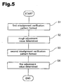
- Fig. 5 is a flowchart depicting the entire routine performed in accordance with the first embodiment of the present invention.
- a first misalignment verification pattern is formed.
- the operator determines a rough adjustment value on the basis of the first misalignment verification pattern and enters the determination information into the printer 20.
- a second misalignment verification pattern is formed on the basis of the rough adjustment value.
- the operator determines a fine adjustment value on the basis of the second misalignment verification pattern and enters the determination information into the printer 20.
- the rough adjustment value corresponds to the first adjustment value referred to in the claims
- the fine adjustment value corresponds to the second adjustment value referred to in the claims.
- Fig. 6 is a diagram depicting an example of the first misalignment verification pattern used to determine a rough adjustment value.
- the first misalignment verification pattern used to determine a rough adjustment value is printed by printer 20.
- the first misalignment verification pattern is composed of a plurality of vertical ruled lines printed in the forward and reverse passes by the black nozzle row K (see Fig. 3). Vertical ruled lines T11 are recorded at regular intervals in the forward passes, whereas vertical ruled lines T12 are recorded in the reverse passes such that their positions in the main scanning direction are gradually shifted in 1/1440-inch increments.
- a plurality of vertical ruled line pairs T1 are printed on the printing paper P such that there is a shift of 1/1440 inch between the relative positions of the vertical ruled lines T11 in the forward pass and the vertical ruled lines T12 in the reverse pass.
- the vertical ruled line pairs T1 constitute the first sub-pattern referred to in the claims.
- the vertical ruled lines T11 of the forward pass are referred to as "the first ruled lines”
- the vertical ruled lines T12 of the reverse pass are referred to as "the second ruled lines.”
- the shift amount of ruled lines in each pair corresponds to a first possible adjustment value.
- Numerals designating shift adjustment numbers are printed below the plurality of groups of vertical ruled line pairs T1.
- the shift adjustment numbers function as correction-related information about the preferred corrected state.
- the term "preferred corrected state” refers to a state in which the positions (in the direction of main scanning) of dots formed in the forward and reverse passes are substantially aligned with each other when the recording positions (or recording timings) in the forward and reverse passes are corrected with appropriate rough adjustment values.
- the vertical ruled line pair whose shift adjustment number is 4 is in the preferred corrected state.
- the CPU 41 prints the first misalignment verification pattern on the basis of data received from the computer 88 by controlling each unit. In other words, the CPU 41 corresponds to the first pattern formation unit referred to in the claims.
- step S2 the user investigates the first misalignment verification pattern, selects the vertical ruled line pair that has the smallest shift, and sends the corresponding shift adjustment number to the user interface screen (not shown) of the printer driver on the computer 88 (see Fig. 2).
- the shift adjustment number is stored in the PROM 43 in the printer 20.
- the shift value associated with the shift adjustment number stored in the PROM 43 is the first adjustment value referred to in the claims.
- the input device (keyboard, mouse, microphone, or the like) of the computer 88 corresponds to the input unit referred to in the claims
- the below-described adjustment number storage area 202a of the PROM 43 corresponds to a first adjustment value storage unit.
- the shift adjustment number may also be entered via the control panel 32 (see Fig. 2). In this case, the control panel 32 corresponds to the input unit.
- Fig. 7 depicts an example of the second misalignment verification pattern, which is used to determine a fine adjustment value.
- step S3 the second misalignment verification pattern used to determine a fine adjustment value is printed by printer 20.
- the second misalignment verification pattern is composed of a plurality of gray patches T2 printed using light cyan, light magenta, and yellow nozzle rows on both the forward pass and the reverse pass.
- the gray patches T2 correspond to the second sub-pattern referred to in the claims.
- a comparatively large dot assembly is depicted for each of the patches T2 in Fig. 7, in practice the patches are formed from visually indistinguishable individual dots.
- the word "gray" in the term "gray patch” does not mean that the patch always appears to the human eye as having a gray color.
- the patch may appear to have any color as long as it is formed using two or more chromatic color inks.
- the dots of each color constituting each patch are recorded at specific positions in the direction of main scanning in the forward passes for each patch.
- the dots are recorded such that their positions in the direction of main scanning are gradually shifted at 1/2880-inch increments from patch to patch.
- the dots of each color constituting each patch are shifted by a common value from patch to patch.
- a plurality of gray patches T2 are printed on the printing paper P such that each patch has a shift, from the previous patch, of 1/2880 inch between the relative positions of the dots formed in the forward pass and the dots formed in the reverse pass.
- the shift amount of each gray patch T2 in the forward and reverse passes corresponds to the second possible adjustment value referred to in the claims.
- Numerals designating shift adjustment numbers are printed below the plurality of gray patches T2, as shown in Fig. 7.
- the shift adjustment numbers function as correction-related information about the preferred corrected state.
- the term "preferred corrected state” refers to a state in which the graininess of the gray patches T2 is minimized when the recording positions (or recording timings) in the forward and reverse passes are corrected with appropriate fine adjustment values. The preferred corrected condition can therefore be expressed by such appropriate fine adjustment values.
- the fine adjustment value of the central patch labeled by the numeral 3 in Fig. 7 is equal to the rough adjustment value of the fourth ruled line pair selected in Fig. 6.
- shift values (second possible adjustment values) forthe gray patches T2 contain a particular fine adjustment value that is equal to the rough adjustment value selected in step S2 (see Fig. 1), and also contain a plurality of values which are sequentially shifted in 1/2880-inch increments toward larger and smaller values from the particular fine adjustment value.
- Such shift values are set by the CPU 41 on the basis of the rough adjustment values entered.
- the CPU 41 corresponds to the second possible adjustment value-setting unit referred to in the claims.
- the example shown in Fig. 7 depicts five gray patches provided with shift adjustment numbers of 1 to 5 and disposed on both sides of the patch labeled by the numeral 3.
- the gray patch labeled by the shift adjustment number 4 indicates a preferred corrected state with the least pronounced graininess.
- the data concerning gray patches are obtained by converting image data representing a uniform dense patch to a binary data format in which images are represented depending on the presence or absence of dots whose ink colors are used during the printing of the second misalignment verification pattern. These data are stored on the hard disk (storage unit) in the computer 88. Each gray patch is printed as the sub-scanning feed pattern performed during actual printing in step S3. An example will now be described with reference to a pattern for sub-scan feeding.
- Figs. 8a and 8b are diagrams depicting a comparison between sub-scanning at a constant feed amount and sub-scanning at a non-constant feed amount.
- Sub-scanning is an operation in which a print medium and/or print head equipped with nozzle groups is caused to move in a direction that intersects the direction of main scanning.
- non-constant feeding refers to a method of feeding during sub-scanning in which a plurality of different feed amounts are combined and used. Performing printing by conducting sub-scanning in the intervals between main scanning passes allows images that extend in the direction perpendicular to the direction of main scanning to be printed on a print medium. In Figs.
- the caption "first scan” indicates the raster lines recorded by a first main scan pass
- the caption “second scan” indicates the raster lines recorded by a second main scan pass that follows the first sub-scan pass.
- raster line refers to pixels arranged in a row in the direction of main scanning.
- pixel refers to a square of an imaginary grid drawn on a print medium in order to define the positions at which dots are to be recorded on the print medium.
- a raster line that is not adjacent to the raster line targeted for recording during a preceding main scan pass is occasionally targeted for recording during a subsequent main scan pass, as illustrated for the second and third scan passes in Fig. 8b.
- the following two problems are encountered when adjacent raster lines are constantly targeted for recording in the manner shown in Fig. 8a.
- the first problem is that smudge is apt to occur between the dots.
- the second problem is that mechanical feed errors related to sub-scanning gradually accumulate, resulting in a significant misalignment between any two adjacent raster lines. Both these problems are factors that degrades picture quality. Using non-constant feeding can address these problems and ultimately product a result that allows picture quality to be improved.
- the second misalignment verification pattern shown in Fig. 7 is printed in accordance with the sub-scanning feed pattern used in the printing of actual images.
- the CPU 41 prints the second misalignment verification pattern on the basis of data received from the computer 88 by controlling each unit. In other words, the CPU 41 corresponds to the second pattern formation unit referred to in the claims.
- step S4 the user analyzes a test pattern printed in the manner shown in Fig. 7 and sends the shift adjustment number of a gray patch with the least pronounced graininess to the user interface screen (not shown) of the printer driver on the computer 88 (see Fig. 2).
- the shift adjustment number is stored in the PROM 43 in the printer 20.
- the shift value associated with the shift adjustment number stored in the PROM 43 is the second adjustment value referred to in the claims.
- the input device (keyboard, mouse, microphone, or the like) of the computer 88 corresponds to the input unit referred to in the claims
- the below-described adjustment number storage area 202b of the PROM 43 corresponds to a second adjustment value storage unit.
- the shift adjustment number may also be entered via the control panel 32 (see Fig. 2) in the same manner as when a rough adjustment value is determined.
- the control panel 32 corresponds to the input unit.
- Fig. 9 is a block diagram depicting parts of a structure for misalignment correction during bidirectional printing in accordance with the first embodiment.
- the PROM 43 of the printer 20 comprises the adjustment number storage areas 202a and 202b, a rough adjustment value table 206a, and a fine adjustment value table 206b.
- a shift adjustment number that expresses the preferred rough adjustment value is stored in the adjustment number storage area 202a.
- the rough adjustment value table 206a is a table for expressing the relation between the rough adjustment values and the shift adjustment numbers in Fig. 6.
- the rough adjustment value table 206a stores the relation between the shift adjustment numbers and the extent (that is, the rough adjustment values) to which the vertical ruled lines of a reverse pass are shifted in terms of recording position in the first misalignment verification pattern shown in Fig. 6.
- a shift adjustment number that expresses the preferred fine adjustment value is stored in the adjustment number storage area 202b.
- the fine adjustment value table 206b is a table for expressing the relation between the fine adjustment values and the shift adjustment numbers in Fig. 7.
- the fine adjustment value table 206b stores the relation between the shift adjustment numbers and the extent (that is, the fine adjustment values) to which the dot recording positions of the reverse pass are shifted in the second misalignment verification pattern shown in Fig. 7.
- Fig. 10 is a flowchart depicting a processing sequence adopted for determining the adjustment values used to correct a misalignment during bidirectional printing.
- the RAM 44 in the printer 20 stores a computer program which functions as a misalignment correction executing unit 210 to correct misalignments during bidirectional printing.
- the misalignment correction executing unit 210 receives an adjustment number from the adjustment number storage area 202a, and also receives the corresponding rough adjustment value from the rough adjustment value table 206a when a notification pertaining to black-and-white printing arrives from the computer 88 (see Fig. 1). Specifically, a notification about black-and-white printing or a notification about color printing is transmitted to the printer 20 as a parameter contained in the print data received from the computer 88.
- the rough adjustment value is the first adjustment value referred to in the claims.
- the misalignment correction executing unit 210 presents the head drive circuit 52 with a signal that specifies the recording timing of the head on the basis of rough adjustment value.
- the misalignment correction executing unit 210 receives an adjustment number from the adjustment number storage area 202b, and a corresponding fine adjustment value is received from the fine adjustment value table 206b.
- the head drive circuit 52 is presented with a signal that specifies the recording timing of the head on the basis of the fine adjustment value.
- the mode for performing black-and-white printing is the first print mode referred to in the claims, and the mode for performing color printing is the second print mode referred to in the claims.
- the misalignment correction executing unit 210 corresponds to "a determination unit", "a first printing unit", or "a second printing unit". Printing performed in accordance with each print mode will now be described.
- the fine adjustment value table 206b is referred to by the misalignment correction executing unit 210, yielding a fine adjustment value that corresponds to an adjustment number stored in the adjustment number storage area 202b of the PROM 43.
- This fine adjustment value is the second adjustment value referred to in the claims.
- the head drive circuit 52 feeds the same drive signal to the three actuator chips 91-93 and adjusts the recording position of the reverse pass in accordance with the recording timing (that is, the delay setting ⁇ T) presented by the misalignment correction executing unit 210.
- the dot recording positions of six nozzle rows are thus adjusted in the reverse pass at a common correction value.
- the fine adjustment value is set at an integral multiple of 1/2880 inch in the direction of main scanning in the above-described manner, the corresponding recording positions (that is, recording timing) can be adjusted in 1/2880-inch increments in the direction of main scanning.
- the adjustment values can be set at an integral multiple of a smaller unit as long as the dots of each color in each patch T2 (see Fig. 7) are shifted at intervals that correspond to this smaller unit.
- correction values can be set within a narrower range if smaller increments are adopted for the shifting between the positions of dots printed in the reverse pass.
- the minimum increment value is determined by the control limitations of the printer.
- the rough adjustment value table 206a is read by the misalignment correction executing unit 210, yielding a rough adjustment value that corresponds to an adjustment number stored in the adjustment number storage area 202a of the PROM 43.
- the misalignment correction executing unit 210 presents the head drive circuit 52 with a signal for defining the recording timing of the head in the same manner as when the correction is made with a fine adjustment value.
- the head drive circuit 52 adjusts the recording positions in the reverse pass in accordance with the recording timing received from the misalignment correction executing unit 210. The dot recording positions of the black nozzle row are thus adjusted with the rough adjustment value in the reverse pass.
- the rough adjustment value is set at an integral multiple of 1/1440 inch in the direction of main scanning in the above-described manner, the recording positions (that is, recording timing) of black-and-white printing can be adjusted in 1/1440-inch increments in the direction of main scanning.
- the rough adjustment value is set with the aim of minimizing the dot formation misalignment of black dots in the direction of main scanning, making it possible to reduce the dot formation misalignment with high efficiency in the direction of main scanning by adjusting the ejection timing of ink drops with the rough adjustment value during monochromatic printing.
- the rough adjustment value is set on the basis of the black nozzle row in the above-described manner, and the fine adjustment value is selected from a plurality of second possible adjustment values whose difference is less than that of the first possible adjustment values lying in the vicinity of the rough adjustment values. Appropriate values can therefore be set without printing large amounts of adjustment patterns even if the fine adjustment value is set using small units.
- the preferred patch can be selected relatively easily because a gray patch with the least pronounced graininess is selected from a limited number of gray patches in accordance with the adjustment values adjacent to the predetermined rough adjustment value.
- a fine adjustment value is determined by printing gray patches using light cyan, light magenta, and yellow inks, which are commonly used to print halftone areas with a pronounced graininess. It is therefore possible to reduce the graininess of such halftone areas and to markedly improve the picture quality of printed matter.
- Gray patches are printed with actual sub-scan feeding which is used in actual color printing.
- a fine adjustment value capable of reducing the graininess of printed matter can therefore be established during actual color printing.
- a rough adjustment value optimized for black nozzles is used when monochromatic images are printed by the black nozzle row alone. This allows that images can be printed with a minimal misalignment in the dots of the black ink used during monochromatic printing, as well as images with a minimal graininess can be obtained during color printing.
- the present invention can also be applied to adjusting the dot formation misalignment of nozzle pairs during unidirectional printing. For example, errors occur when the actuator chips are manufactured or when the print head is mounted on the carriage. For this reason, the impact positions (dot formation positions) of ink drops vary slightly from nozzle to nozzle when the ink drops are ejected during the same main scan. Any dot formation misalignment occurring in such cases can be adjusted by adopting the arrangement described below.
- Fig. 11 is a block diagram depicting parts of a structure whereby any shifting occurring during printing is corrected in accordance with a second embodiment.
- the structure in this block diagram is the same as that of the block diagram in Fig. 9 except for the structure of the head drive circuit and actuator chips.
- the printing device of the second embodiment is designed to perform unidirectional printing by ejecting ink drops during a single main scan.
- the printing device of the second embodiment has an independent head drive circuit 52c that is separate from the other actuator chips and is designed for use with an actuator chip 93 for actuating the light cyan and yellow nozzle rows. For this reason, the ejection timing of light magenta and yellow inks can be shifted relative to the inks of other colors. In all other respects this device is identical to the printing device of the first embodiment.
- Fig. 12 is a flowchart depicting the entire procedure involved in the second embodiment.
- a first misalignment verification pattern is formed in step S11.
- upper vertical ruled lines (T11 in Fig. 6) are first formed at regular intervals by making use of the light cyan nozzle row.
- Lower vertical ruled lines (T12 in Fig. 6) are formed while gradually shifted in 1/1440-inch increments by the use of the light magenta nozzle row. Since the printing device of the second embodiment is designed for unidirectional printing, the vertical ruled lines are always formed during identically oriented main scans.
- step S12 the operator provides the printer 20 with the adjustment number of the most closely matching vertical ruled line pairs. Rough adjustment values are thus determined.
- a second misalignment verification pattern is formed based on the rough adjustment values.
- the gray patches of the second misalignment verification pattern are formed using light cyan, light magenta, and yellow inks in the same manner as in the first embodiment. It should be noted, however, that whereas the light cyan dots constituting each patch are recorded at constant positions within the patch in the direction of main scanning, the light magenta and yellow dots are recorded while their positions in the direction of main scanning are gradually shifted in 1/2880-inch increments from patch to patch. The light magenta and yellow dots are shifted by a common value from patch to patch.
- the light magenta and yellow nozzle rows are actuated by the common actuator chip 93, and the actuator chip 93 has an independently operating head drive circuit 52c.
- step S14 the operator provides the printer 20 with the adjustment number of the patches having the least pronounced grainy feel. Fine adjustment values are thus determined.
- the misalignment correction executing unit 210 receives adjustment number from the adjustment number storage area 202b, and also receives the corresponding fine adjustment values from the fine adjustment value table 206b during color printing.
- the head drive circuit 52c is provided with signals for identifying the recording timing of the head on the basis of the fine adjustment values.
- the head drive circuits for actuating the other nozzle rows does not receive any signals for correcting the dot formation positions. As a result, the positions at which light cyan and yellow dots are formed are adjusted in relation to the dots of other colors. Adopting such an arrangement makes it possible to adjust the dot formation misalignment between nozzles during unidirectional printing.
- Fig. 13 is a diagram depicting an example of a dot arrangement constituting a gray patch T2.
- the printer of the third embodiment has the same hardware structure as the printer used in the first embodiment.
- a pattern (such as the one shown in Fig. 13) in which dots are arranged in a regular manner in the directions of main scanning and sub-scanning is printed as the gray patch T2 (referred to as "test pattern" throughout the description of the third embodiment given below).
- Fig. 13 is designed to schematically depict dot arrangements and does not reflect the number or size of dots in an actual gray patch T2.
- the round dots Df are formed in the forward pass of the carriage 30, and the square dots Db are formed in the reverse pass.
- the test pattern in Fig. 13a is obtained by adopting a procedure in which a row of forward-pass dots Df aligned in the direction of main scanning and a row of reverse-pass dots Db aligned in the direction of main scanning are alternately arranged in the direction of sub-scanning.
- the data for the test pattern are organized such that the distance between the center positions of the dots is equal to a constant value D1 in the direction of sub-scanning and to a constant value D2 in the direction of main scanning when the ink drops are ejected with correct timing.
- the square dots Db are shifted to the left in the drawing when the timing with which ink drops are ejected in the reverse pass lags behind the perfect timing.
- This brings about a reduction in the interval D2a between the dots Db and the dots Df on the left, and an increase in the interval D2b between the dots Db and the dots Df on the right.
- a situation in which ink drops are ejected more rapidly in the reverse pass causes the square dots Db to shift to the right, resulting in an increased interval D2a and a reduced interval D2b.
- Such variations can be visually detected by the user as changes in the appearance of the test pattern involved, allowing the user to select a test pattern in which ink drops are recorded by being ejected with correct ejection timing.
- adopting an approach in which the dots Df formed in the forward pass and the dots Db formed in the reverse pass are obtained using different ink colors makes it possible to create perceptible color irregularities and other visible changes even when the distance between the dots of different colors varies only slightly. Any dot formation misalignment can therefore be detected with ease.
- Fig. 13b is a diagram depicting another example of the dot arrangement constituting a gray patch T2.
- the dots formed in the forward pass are aligned in the direction of sub-scanning, and the dots formed in the reverse pass are aligned in the direction of main scanning.
- the test pattern shown in Fig. 13b is configured such that the dots formed in the forward pass and the dots formed in the reverse pass are alternately arranged in the direction of sub-scanning as well.
- 13b is also configured such that the distance between the centers of dots in the direction of main scanning is equal to a constant value D1, and the distance in the direction of sub-scanning is equal to a constant value D2 when the ink drops are ejected with correct timing.
- test patterns are not limited to the above-described arrangements and include other options as long as they involve using inks of two or more colors. Nor is it necessary for the patterns to appear to have a gray color.
- the interval between the dots in a test pattern should be 0.5-2.5 mm, and preferably 0.7-1.5 mm. Ideally, the interval should fall within a specific range in the vicinity of 1.0 mm.
- the interval between the dots in a test pattern should be 0.5-2.5 mm, and preferably 0.7-1.5 mm. Ideally, the interval should fall within a specific range in the vicinity of 1.0 mm.
- Fig. 14 is a graph depicting the relation between spatial frequency and visibility.
- This graph known as the spatial frequency characteristic of vision (VTF: Visual Transfer Function), is obtained by plotting spatial frequency on the horizontal axis, and visibility at each spatial frequency on the vertical axis. It is common knowledge that human visibility in relation to video noise varies with spatial frequency.
- spatial frequency is an inverse of the interval between the dots in a printed test pattern. It can be concluded based on the graph in Fig. 14 that visibility is relatively high at a spatial frequency of 0.4-2.0 cycle/mm and reaches its maximum at about 1 cycle/mm.
- the dots recorded in the forward pass and the dots recorded in the reverse pass were formed at 0.5 to 2.5-mm intervals.
- a spatial frequency of 0.4-2.0 cycle/mm corresponds to a dot interval of 0.5-2.5 mm.
- the spatial frequency falls within a specific range in the vicinity of 1.0 cycle/mm when the interval between dots recorded in the forward pass and dots recorded in the reverse pass falls within a specific range in the vicinity of 1.0 mm.
- a dot recording position is shifted in the direction of main scanning by a shift in the timing for ejecting ink drops. It is therefore sufficient to select solely in the direction of main scanning a spatial frequency that increases visibility when a test pattern is created. If visibility in relation to brightness is different in the vertical and horizontal directions, it is possible to adopt an approach in which the corresponding visibility-enhancing spatial frequencies are combined to obtain intervals D1 and D2.
- the inks that can be used are not limited to these combinations.
- the gray patches can be printed using magenta, cyan, and yellow inks when the inks of these three colors are used as the chromatic color inks of color printing.
- the color combinations may not be limited to above three colors (yellow, light magenta, and light cyan), and patches can be printed using other ink combinations. In other words, any color combination is permissible as long as a color patch is formed using two or more single chromatic color nozzle groups.
- a rectilinear or other pattern formed with intermittently recorded dots can be used instead of the vertical ruled lines as the first misalignment verification pattern for setting rough adjustment values.
- any misalignment verification pattern can be used as long as this pattern allows correction information about the preferred corrected states to be selected and correction values to be determined.
- Configuring the first misalignment verification pattern as a rectilinear pattern obtained by the intermittent recording of dots allows this pattern to be formed by a single main scan (without a sub-scan) even for nozzles incapable of forming continuous dots in the direction of sub-scanning.
- the first embodiment was described with reference to a case in which dot formation misalignments were adjusted using rough adjustment values during black-and-white printing. It is also possible, however, to adjust dot formation misalignments with the aid of fine adjustment values during black-and-white printing.
- the first embodiment was described with reference to a case in which black ink was used to print patterns for determining rough adjustment values. It is also possible, however, to use one or more types of non-black inks to print patterns for determining the rough adjustment values in an arrangement in which dot recording positions are adjusted using fine adjustment values during black-and-white printing.
- the first misalignment verification pattern for determining rough adjustment values can be printed on a print medium by one or more single-color nozzle groups.
- vertical ruled lines T12 are formed while their positions in the direction of main scanning are shifted in 1/1440-inch increments, and a plurality of first possible adjustment values are set at a difference that corresponds to a shift of 1/1440 inch. It was assumed that the dots of each color in a gray patch were recorded such that their positions in the direction of main scanning in the reverse pass were shifted in 1/2880-inch increments and that a plurality of second possible adjustment values were set at a difference that corresponded to a shift of 1/2880 inch.
- Such an arrangement allows black-and-white printing, which is characterized by large numbers of characters or diagrams being printed, to be performed such that characters or diagrams only minimally shifted in the direction of main scanning are formed using first adjustment values (rough adjustment values in the first embodiment; see Fig. 6) selected on the basis of ruled lines.
- Color printing which is characterized by large numbers of images being printed, can be performed such that images having a minimal grainy feel are formed using second adjustment values (fine adjustment values in the first embodiment; see Fig. 7) selected on the basis of gray patches.
- second adjustment values are set in the vicinity of the first adjustment values.
- the first and second adjustment values designed to cancel shifting can thereby be set with high efficiency when the dot formation misalignments of the nozzles contain dot formation misalignments that are independent of individual nozzles and are common to all the nozzles.
- misalignments were corrected by adjusting the recording positions (or recording timings) in the reverse pass
- the misalignments may be corrected by adjusting the recording positions both in the forward pass and reverse pass.
- misalignments should ordinarily be corrected by adjusting the recording positions in the forward pass and/or reverse pass.
- the present invention is not limited to ink-jet printers alone and can be adapted to a variety of printing devices in which printing is accomplished with a print head.
- the present invention is not limited to methods or devices for ejecting ink drops and includes methods and devices for recording dots by other means.
- software can be used to perform some of the hardware functions, or, conversely, hardware can be used to perform some of the software functions.
- some of the functions performed by the head drive circuit 52 shown in Fig. 12 can be performed by software.
- the present invention can be adapted to a variety of ink-jet printers and other image output devices for outputting images with the aid of dots.
Abstract
Description
Claims (37)
- A method for setting adjustment values designed to reduce dot formation misalignment in a direction of main scanning during a printing process in which a printing device equipped with a plurality of single-color nozzle groups for ejecting ink drops having mutually different colors is used to deposit the ink drops and to form dots on a print medium while the plurality of single-color nozzle groups and/or the print medium is moved in a main scan, the method comprising the steps of:(a) selecting a first adjustment value from a plurality of first possible adjustment values using a first misalignment verification pattern; and(b) selecting a second adjustment value from a plurality of second possible adjustment values using a second misalignment verification pattern, which is different from the first misalignment verification pattern.
- An adjustment value determination method as defined in Claim 1, wherein the step (b) comprises a step of setting the plurality of second possible adjustment values in a vicinity of the first adjustment value.
- An adjustment value determination method as defined in Claim 2, wherein the step (b) further comprises the step of:(b1) selecting the second adjustment value from the plurality of second possible adjustment values whose difference is less than a difference between the plurality of first possible adjustment values.
- An adjustment value determination method as defined in Claim 3, wherein the step (a) comprises the steps of:the step (b) further comprises the steps of:(a1) forming the first misalignment verification pattern on a print medium by one or more single-color nozzle groups, wherein the first misalignment verification pattern contains a plurality of first sub-patterns associated with the plurality of first possible adjustment values, respectively; and(a2) setting the first adjustment value in accordance with correction information about a preferred corrected state selected from the first misalignment verification pattern; and(b2) forming the second misalignment verification pattern on a print medium by two or more of the single-color nozzle groups, wherein the second misalignment verification pattern contains a plurality of second sub-patterns associated with the plurality of second possible adjustment values, respectively; and(b3) setting the second adjustment value in accordance with correction information about a preferred corrected state selected from the second misalignment verification pattern.
- An adjustment value determination method as defined in Claim 4, wherein the step (a1) comprises the steps of:(a11) printing first ruled lines each contained in the first sub-pattern and oriented in a direction that intersects the direction of main scanning; and(a12) printing second ruled lines each contained in the first sub-pattern, oriented in a direction that intersects the direction of main scanning and associated with the first ruled line.
- An adjustment value determination method as defined in Claim 5, wherein the adjustment values are designed to reduce dot formation misalignments in the direction of main scanning during a printing process in which ink drops are deposited and dots are formed on a print medium while the main scanning is performed in opposite directions;the step (a11) comprises the step of:(a111) printing the first ruled lines in a forward pass of the main scan; andthe step (a12) comprises the step of:(a121) printing the second ruled lines in a reverse pass of the main scan.
- An adjustment value determination method as defined in Claim 5, wherein the step (a11) comprises the step of:the step(a12) comprises the step of:(a112) printing the first ruled lines by a specific single-color nozzle group; and(a122) printing the second ruled lines by a single-color nozzle group that is different from the single-color nozzle group used in the printing of the first ruled lines.
- An adjustment value determination method as defined in Claim 4, wherein the step (b2) comprises the step of:(b21) forming uniform color patches as the second sub-patterns.
- An adjustment value determination method as defined in Claim 4, wherein the step (b2) comprises the step of:(b21) forming the second sub-patterns by forming dots such that a value of 0.5-2.5 mm is selected for intervals between the dots formed by ink drops ejected from nozzles in a same single-color nozzle group.
- An adjustment value determination method as defined in Claim 4, wherein the adjustment values are designed to reduce dot formation misalignments in the direction of main scanning during a printing process in which ink drops are deposited and dots are formed on a print medium while main scanning is performed in opposite directions; and
the step(b2) comprises the step of:(b21) printing the second sub-patterns in forward and reverse passes of the main scan. - An adjustment value determination method as defined in Claim 4, wherein
the printing device carries out printing process performing sub-scans between main scans, wherein the plurality of single-color nozzle groups and/or the print medium is moved in a direction that intersects the direction of main scanning in the sub-scan; and
the step(b2) comprises the step of:(b21) forming the second sub-patterns while performing sub-scanning between main scans according to a repeating pattern of sub-scanning feed amounts performed between the main scans during image printing. - An adjustment value determination method as defined in Claim 4, wherein the plurality of single-color nozzle group comprises a plurality of single chromatic color nozzle groups for ejecting single chromatic color inks; and step (b2) comprises the step of:(b21) forming the second sub-patterns using two or more of the single chromatic color nozzle groups.
- An adjustment value determination method as defined in Claim 12, wherein the plurality of single-color nozzle groups further comprises a single achromatic color nozzle group for ejecting single achromatic color ink;
the step(a1) comprises the step of:the adjustment value determination method further comprises the steps of:(a13) forming the first misalignment verification pattern using the single achromatic color nozzle group; and(c) storing the first adjustment value as a value for a first print mode using only the single achromatic color nozzle group; and(d) storing the second adjustment value as a value for a second print mode using at least one of the single chromatic color nozzle groups. - An adjustment value determination method as defined in Claim 2, wherein the step (a) comprises the steps of:the step(b) comprises the steps of:(a1) forming the first misalignment verification pattern on a print medium such that the first misalignment verification pattern contains a plurality of first sub-patterns associated with the first possible adjustment values, respectively, each first sub-pattern having a first ruled line whose direction intersects the direction of main scanning, and also having a second ruled line associated with the first ruled line and oriented in a direction that intersects the direction of main scanning; and(a2) setting the first adjustment value in accordance with correction information about a preferred corrected state selected from the first misalignment verification pattern; and(b1) forming the second misalignment verification pattern on a print medium such that the second misalignment verification pattern contains a plurality of second sub-patterns reproduced as uniform color patches and associated with the second adjustment values, respectively; and(b2) setting the second adjustment value in accordance with correction information about a preferred corrected state selected from the second misalignment verification pattern.
- An adjustment value determination method as defined in Claim 14, wherein the step (b1) comprises the step of:(b11) forming the second sub-patterns by forming dots such that a value of 0.5-2.5 mm is selected for intervals between the dots formed by ink drops ejected from nozzles included in a same single-color nozzle group.
- An adjustment value determination method as defined in Claim 14, wherein the step (b1) comprises the step of:(b11) forming the second sub-patterns associated with the plurality of second possible adjustment values whose difference is equal to a difference between the plurality of first possible adjustment values.
- An adjustment value determination method as defined in Claim 14, wherein the plurality of single-color nozzle groups includes:the step (a1) comprises the step of:a single achromatic color nozzle group for ejecting single achromatic color ink; anda plurality of single chromatic color nozzle groups for ejecting corresponding single chromatic color inks;the step (b1) comprises the step of:(a11) forming the first misalignment verification pattern using the single achromatic color nozzle group;the adjustment value determination method further comprises the steps of:(b11) forming the second sub-patterns using two or more of the single chromatic color nozzle groups; and(c) storing the first adjustment value as a value for a first print mode using only the single achromatic color nozzle group; and(d) storing the second adjustment value as a value for a second print mode using at least one of the single chromatic color nozzle groups.
- A printing device for performing printing by ejecting ink drops from nozzles, depositing the drops on a print medium to form dots, the printing device comprising:a plurality of single-color nozzle groups for ejecting ink drops having mutually different colors;a main scanning unit configured to move the plurality of single-color nozzle groups and/or the print medium in a main scan;an input unit configured to receive a data input from outside; anda control unit configured to control the printing process;the control unit comprising:a first pattern-forming unit configured to form on a print medium a first misalignment verification pattern containing a plurality of first sub-patterns associated with first possible adjustment values, respectively, contemplated for use toreduce dot formation misalignments in a direction of main scanning;a second possible adjustment value setting unit configured to set a plurality of second possible adjustment values contemplated to reduce the dot formation misalignment in the direction of main scanning;a second pattern-forming unit configured to form on a print medium a second misalignment verification pattern containing a plurality of second sub-patterns associated with the second possible adjustment values, respectively; anda second adjustment value storage unit configured to store a second adjustment value selected from the second possible adjustment values and entered via the input unit.
- A printing device as defined in Claim 18, wherein the plurality of second possible adjustment values are adjustment values set in a vicinity of a first adjustment value selected from the first possible adjustment values and entered via the input unit.
- A printing device as defined in Claim 19, wherein a difference between the plurality of second possible adjustment values is less than a difference between the plurality of first possible adjustment values.
- A printing device as defined in Claim 20, wherein the first pattern-forming unit is configured to form the first misalignment verification pattern by means of one or more of the single-color nozzle groups; and
the second pattern-forming unit forms the second misalignment verification pattern by means of two or more of the single-color nozzle groups. - A printing device as defined in Claim 19, wherein the first pattern-forming unit is configured to print:first ruled lines each contained in the first sub-pattern and oriented in a direction that intersects the direction of main scanning; andsecond ruled lines each contained in the first sub-pattern, oriented in a direction that intersects the direction of main scanning and associated with the first ruled line.
- A printing device as defined in Claim 22, wherein the control unit is configured to carry out printing process by depositing ink drops and forming dots on a print medium while performing the main scanning in opposite directions; and
the first pattern-forming unit is configured to print:the first ruled lines in a forward pass of the main scan; andthe second ruled lines in a reverse pass of the main scan. - A printing device as defined in Claim 22, wherein the first pattern-forming unit is configured to print:the first ruled lines by a specific single-color nozzle group; andthe second ruled lines by a single-color nozzle group that is different from the single-color nozzle group used in the printing of the first ruled lines.
- A printing device as defined in Claim 19, wherein the second pattern-forming unit is configured to form uniform color patches as the second sub-patterns.
- A printing device as defined in Claim 21, wherein the second pattern-forming unit is configured to form the second sub-patterns by forming dots such that a value of 0.5-2.5 mm is selected for intervals between the dots formed by ink drops ejected from nozzles in a same single-color nozzle group.
- A printing device as defined in Claim 21, wherein the control unit is configured to carry out printing process by depositing ink drops and forming dots on a print medium while performing the main scan in opposite directions; and
the second pattern-forming unit is configured to print the second sub-patterns in forward and reverse passes of the main scan. - A printing device as defined in Claim 21, further comprising a sub-scanning unit configured to move the plurality of single-color nozzle groups and/or the print medium in a sub-scan in a direction that intersects the direction of main scanning; wherein
the second pattern-forming unit is configured to form the second sub-patterns while performing sub-scanning between main scans according to a repeating pattern of sub-scanning feed amounts performed between the main scans during image printing. - A printing device as defined in Claim 21, wherein the plurality of single-color nozzle group comprises a plurality of single chromatic color nozzle groups for ejecting single chromatic color inks; and the second pattern-forming unit is configured to form the second sub-patterns using two or more of the single chromatic color nozzle groups.
- A printing device as defined in Claim 29, wherein the control unit further comprises a first adjustment value storage unit configured to store the first adjustment value; wherein
the plurality of single-color nozzle groups further comprises a single achromatic color nozzle group for ejecting single achromatic color ink;
the first pattern-forming unit is configured to form the first misalignment verification pattern using the single achromatic color nozzle group; and
the control unit further comprises:a first printing unit configured to carry out printing process using the first adjustment value in the first adjustment value storage unit in a first print mode using only the single achromatic color nozzle group; anda second printing unit configured to carry out printing process using the second adjustment value in the second adjustment value storage unit in a second print mode using at least one of the single chromatic color nozzle groups. - A printing device as defined in Claim 19, wherein the first sub-pattern comprises:the second sub-pattern is reproduced as uniform color patches.first ruled line whose direction intersects the direction of main scanning; andsecond ruled line associated with the first ruled line and oriented in a direction that intersects the direction of main scanning; and
- A printing device as defined in Claim 31, wherein the second sub-pattern contains dots such that a value of 0.5-2.5 mm is selected for intervals between the dots formed by ink drops ejected from nozzles included in a same single-color nozzle group.
- A printing device as defined in Claim 31, wherein
a difference of the plurality of second possible adjustment values is equal to a difference between the plurality of first possible adjustment values. - A printing device as defined in Claim 31, wherein the control unit further comprises a first adjustment value storage unit configured to store the first adjustment value;
the plurality of single-color nozzle groups comprise:the first pattern-forming unit is configured to form the first misalignment verification pattern using the single achromatic color nozzle group;a single achromatic color nozzle group for ejecting single achromatic color ink; anda plurality of single chromatic color nozzle groups for ejecting corresponding single chromatic color inks;
the second pattern-forming unit is configured to form the second sub-patterns using two or more of the single chromatic color nozzle groups; and
the control unit further comprises:a first printing unit configured to carry out printing process using the first adjustment value in the first adjustment value storage unit in a first print mode using only the single achromatic color nozzle group; anda second printing unit configured to carry out printing process using the second adjustment value in the second adjustment value storage unit in a second print mode using at least one of the single chromatic color nozzle groups. - A printing device as defined in Claim 34, wherein the control unit further comprises a determination unit configured to determine whether printing is performed according to the first or second print mode on the basis of a print data input; and
the first or second print unit prints images on the basis of the decision made by the determination unit. - A computer-readable medium containing a computer program for forming misalignment verification patterns that are used when adjustment values are determined in a computer with a printing device equipped with a plurality of single-color nozzle groups for ejecting ink drops having mutually different colors in order to reduce dot formation misalignments in a direction of main scanning during a printing process in which ink drops are deposited and dots are formed on a print medium while the plurality of single-color nozzle groups and/or the print medium is moved in a main scan, the computer-readable medium containing a computer program causing the computer to implement the functions of:forming on a print medium a first misalignment verification pattern containing a plurality of first sub-patterns associated with first possible adjustment values, respectively, contemplated to reduce dot formation misalignments in the direction of main scanning;setting a plurality of second possible adjustment values contemplated to reduce the dot formation misalignment in the direction of main scanning and selected from a vicinity of a first adjustment value selected from among the first possible adjustment values and entered through the input unit;forming on a print medium a second misalignment verification pattern containing a plurality of second sub-patterns associated with the plurality of second possible adjustment values, respectively; andreceiving and storing a second adjustment value selected from the second possible adjustment values.
- A storage medium as defined in Claim 36 containing data concerning the second sub-patterns, in which dots are formed by ink drops of a same color at 0.5- to 2.5-mm intervals.
Applications Claiming Priority (3)
| Application Number | Priority Date | Filing Date | Title |
|---|---|---|---|
| JP2000157666A JP3654141B2 (en) | 2000-05-29 | 2000-05-29 | Determination of the adjustment value of the recording position deviation during printing using two types of inspection patterns |
| JP2000157666 | 2000-05-29 | ||
| PCT/JP2001/004425 WO2001092015A1 (en) | 2000-05-29 | 2001-05-25 | Determination of value of adjustment for recording position variation in printing using two types of inspection pattern |
Publications (4)
| Publication Number | Publication Date |
|---|---|
| EP1221371A1 true EP1221371A1 (en) | 2002-07-10 |
| EP1221371A4 EP1221371A4 (en) | 2003-07-16 |
| EP1221371B1 EP1221371B1 (en) | 2006-08-16 |
| EP1221371B8 EP1221371B8 (en) | 2006-11-02 |
Family
ID=18662255
Family Applications (1)
| Application Number | Title | Priority Date | Filing Date |
|---|---|---|---|
| EP01932280A Expired - Lifetime EP1221371B8 (en) | 2000-05-29 | 2001-05-25 | Determination of value of adjustment for recording position variation in printing using two types of inspection pattern |
Country Status (6)
| Country | Link |
|---|---|
| US (2) | US6700593B2 (en) |
| EP (1) | EP1221371B8 (en) |
| JP (1) | JP3654141B2 (en) |
| AT (1) | ATE336376T1 (en) |
| DE (1) | DE60122276T2 (en) |
| WO (1) | WO2001092015A1 (en) |
Cited By (1)
| Publication number | Priority date | Publication date | Assignee | Title |
|---|---|---|---|---|
| EP1391309A1 (en) * | 2002-08-20 | 2004-02-25 | Seiko Epson Corporation | Printing method, printing apparatus, computer-readable medium, and correction pattern |
Families Citing this family (31)
| Publication number | Priority date | Publication date | Assignee | Title |
|---|---|---|---|---|
| JP3654141B2 (en) * | 2000-05-29 | 2005-06-02 | セイコーエプソン株式会社 | Determination of the adjustment value of the recording position deviation during printing using two types of inspection patterns |
| US6964465B2 (en) * | 2002-02-21 | 2005-11-15 | Seiko Epson Corporation | Printing apparatus, storage medium having a program recorded thereon, pattern, computer system, and printing method |
| JP4193458B2 (en) * | 2002-10-03 | 2008-12-10 | セイコーエプソン株式会社 | Adjusting the recording position misalignment during bidirectional printing |
| JP4103612B2 (en) * | 2003-02-06 | 2008-06-18 | セイコーエプソン株式会社 | Liquid ejecting apparatus and method for adjusting position of nozzle row thereof |
| JP4208604B2 (en) * | 2003-02-26 | 2009-01-14 | キヤノン株式会社 | Ink jet recording apparatus and recording control method in ink jet recording apparatus |
| JP4608847B2 (en) * | 2003-05-01 | 2011-01-12 | セイコーエプソン株式会社 | Liquid ejection apparatus, correction pattern, correction pattern forming method, and liquid ejection system |
| JP4529396B2 (en) * | 2003-09-18 | 2010-08-25 | セイコーエプソン株式会社 | Printing apparatus, test pattern, and printing method |
| JP3826931B2 (en) * | 2003-10-30 | 2006-09-27 | 村田機械株式会社 | Color image processing device |
| JP4262070B2 (en) * | 2003-12-02 | 2009-05-13 | キヤノン株式会社 | Element base of recording head, recording head, and control method of recording head |
| EP1541354B1 (en) * | 2003-12-09 | 2008-11-26 | Brother Kogyo Kabushiki Kaisha | Inkjet head and nozzle plate of inkjet head |
| US20050151769A1 (en) * | 2004-01-12 | 2005-07-14 | Fuji Xerox Co., Ltd. | Method and system for compensating for systematic variability in fluid ejection systems to improve fluid ejection quality |
| US20050270325A1 (en) * | 2004-06-07 | 2005-12-08 | Cavill Barry R | System and method for calibrating ink ejecting nozzles in a printer/scanner |
| JP4506323B2 (en) * | 2004-07-16 | 2010-07-21 | セイコーエプソン株式会社 | Error information acquisition apparatus, error information acquisition method, error information acquisition program, print control apparatus, print control method, and print control program |
| JP4592067B2 (en) * | 2004-08-18 | 2010-12-01 | キヤノン株式会社 | Inkjet recording apparatus and recording position setting method of the apparatus |
| WO2007039444A1 (en) * | 2005-09-20 | 2007-04-12 | Agfa Graphics Nv | A method and apparatus for automatically aligning arrays of printing elements |
| EP1764996A1 (en) * | 2005-09-20 | 2007-03-21 | Agfa Graphics N.V. | A method and apparatus for automatically aligning arrays of printing elements |
| US7419246B2 (en) * | 2006-03-01 | 2008-09-02 | Lexmark International, Inc. | Flexible circuits, flexible circuit assemblies and assemblies for use with fluid ejection apparatuses |
| JP4174534B2 (en) * | 2006-08-01 | 2008-11-05 | キヤノン株式会社 | Recording device |
| TWI321748B (en) * | 2006-09-21 | 2010-03-11 | Qisda Corp | Method and printing system capable of verifying and compensating skewness of a printhead |
| JP5004335B2 (en) * | 2007-02-02 | 2012-08-22 | キヤノン株式会社 | Recording position adjusting method, recording system, host device, and program |
| JP2008229922A (en) | 2007-03-18 | 2008-10-02 | Ricoh Co Ltd | Image forming apparatus, method for detecting contamination of linear encoder, and method for forming image for linear encoder contamination detection |
| JP4530020B2 (en) * | 2007-10-01 | 2010-08-25 | ブラザー工業株式会社 | Image forming apparatus |
| JP5473434B2 (en) * | 2009-06-30 | 2014-04-16 | キヤノン株式会社 | Image processing apparatus, image processing system, image processing method, and program |
| JP2011115986A (en) * | 2009-12-01 | 2011-06-16 | Seiko Epson Corp | Liquid ejecting apparatus and ejection timing correcting method |
| JP5333394B2 (en) * | 2010-09-15 | 2013-11-06 | ブラザー工業株式会社 | Image processing device |
| JP5764976B2 (en) * | 2011-03-03 | 2015-08-19 | セイコーエプソン株式会社 | Dot formation position adjusting apparatus, recording method, setting method, and recording program |
| US9016820B2 (en) * | 2011-08-24 | 2015-04-28 | Canon Kabushiki Kaisha | Printing apparatus and control method thereof |
| JP6291777B2 (en) * | 2012-12-05 | 2018-03-14 | 株式会社リコー | Image forming apparatus, test pattern forming method, and program |
| JP6213778B2 (en) * | 2014-03-04 | 2017-10-18 | ブラザー工業株式会社 | Print production device |
| US9566799B1 (en) * | 2015-10-14 | 2017-02-14 | Funai Electric Co., Ltd. (Jp) | Imaging apparatus and method for reducing banding |
| JP2018089920A (en) * | 2016-12-07 | 2018-06-14 | セイコーエプソン株式会社 | Printing method and printer |
Citations (6)
| Publication number | Priority date | Publication date | Assignee | Title |
|---|---|---|---|---|
| JPH0781190A (en) * | 1993-09-20 | 1995-03-28 | Canon Inc | Ink-test printing method and ink jet recorder |
| EP0874329A2 (en) * | 1997-04-24 | 1998-10-28 | Seiko Epson Corporation | Method and apparatus for aligning print |
| EP0895869A2 (en) * | 1997-07-31 | 1999-02-10 | Seiko Epson Corporation | Method of printing test pattern and printing apparatus for the same |
| EP0947323A2 (en) * | 1998-04-03 | 1999-10-06 | Canon Kabushiki Kaisha | An adjustment method of dot printing positions and a printing apparatus |
| EP1002651A2 (en) * | 1998-11-19 | 2000-05-24 | Sharp Kabushiki Kaisha | Serial printer and method of adjusting the recording sheet displacement |
| EP1027999A2 (en) * | 1999-02-10 | 2000-08-16 | Seiko Epson Corporation | Positional deviation correction using different correction values for monochrome and color bi-directional printing |
Family Cites Families (15)
| Publication number | Priority date | Publication date | Assignee | Title |
|---|---|---|---|---|
| US4198642A (en) | 1978-01-09 | 1980-04-15 | The Mead Corporation | Ink jet printer having interlaced print scheme |
| JPH02243373A (en) * | 1989-03-17 | 1990-09-27 | Hitachi Ltd | Print misregistration correcting method and printer for practicing same method |
| JPH0569625A (en) | 1991-09-11 | 1993-03-23 | Seiko Epson Corp | Serial printer |
| DE69435024T2 (en) | 1993-05-27 | 2008-06-12 | Canon K.K. | Method and apparatus for ink jet recording |
| JP3254982B2 (en) * | 1995-10-06 | 2002-02-12 | セイコーエプソン株式会社 | Printing position adjustment method for color printer and color printer |
| JP3560305B2 (en) * | 1997-03-28 | 2004-09-02 | キヤノン株式会社 | Recording device and check pattern recording method |
| JP3591286B2 (en) * | 1997-04-24 | 2004-11-17 | セイコーエプソン株式会社 | Timing adjustment method, printing device, and adjustment pattern creation method |
| JP3858344B2 (en) * | 1997-05-23 | 2006-12-13 | ブラザー工業株式会社 | Printing method and printing apparatus |
| JP3941160B2 (en) * | 1997-06-04 | 2007-07-04 | ブラザー工業株式会社 | Serial printer |
| JP4006786B2 (en) | 1997-07-31 | 2007-11-14 | セイコーエプソン株式会社 | Test dot recording method and printer |
| US6109722A (en) * | 1997-11-17 | 2000-08-29 | Hewlett-Packard Company | Ink jet printing system with pen alignment and method |
| JP2000062156A (en) * | 1998-08-26 | 2000-02-29 | Oki Data Corp | Liquid jet recorder and adjusting method therefor |
| JP2000127360A (en) * | 1998-10-23 | 2000-05-09 | Canon Inc | Recorder and print position correcting method |
| US6281908B1 (en) * | 1999-04-15 | 2001-08-28 | Lexmark International, Inc. | Alignment system and method of compensating for skewed printing in an ink jet printer |
| JP3654141B2 (en) * | 2000-05-29 | 2005-06-02 | セイコーエプソン株式会社 | Determination of the adjustment value of the recording position deviation during printing using two types of inspection patterns |
-
2000
- 2000-05-29 JP JP2000157666A patent/JP3654141B2/en not_active Expired - Lifetime
-
2001
- 2001-05-25 DE DE60122276T patent/DE60122276T2/en not_active Expired - Lifetime
- 2001-05-25 US US10/048,287 patent/US6700593B2/en not_active Expired - Fee Related
- 2001-05-25 AT AT01932280T patent/ATE336376T1/en not_active IP Right Cessation
- 2001-05-25 EP EP01932280A patent/EP1221371B8/en not_active Expired - Lifetime
- 2001-05-25 WO PCT/JP2001/004425 patent/WO2001092015A1/en active IP Right Grant
-
2004
- 2004-01-09 US US10/753,771 patent/US6886904B2/en not_active Expired - Lifetime
Patent Citations (6)
| Publication number | Priority date | Publication date | Assignee | Title |
|---|---|---|---|---|
| JPH0781190A (en) * | 1993-09-20 | 1995-03-28 | Canon Inc | Ink-test printing method and ink jet recorder |
| EP0874329A2 (en) * | 1997-04-24 | 1998-10-28 | Seiko Epson Corporation | Method and apparatus for aligning print |
| EP0895869A2 (en) * | 1997-07-31 | 1999-02-10 | Seiko Epson Corporation | Method of printing test pattern and printing apparatus for the same |
| EP0947323A2 (en) * | 1998-04-03 | 1999-10-06 | Canon Kabushiki Kaisha | An adjustment method of dot printing positions and a printing apparatus |
| EP1002651A2 (en) * | 1998-11-19 | 2000-05-24 | Sharp Kabushiki Kaisha | Serial printer and method of adjusting the recording sheet displacement |
| EP1027999A2 (en) * | 1999-02-10 | 2000-08-16 | Seiko Epson Corporation | Positional deviation correction using different correction values for monochrome and color bi-directional printing |
Non-Patent Citations (2)
| Title |
|---|
| PATENT ABSTRACTS OF JAPAN vol. 1995, no. 06, 31 July 1995 (1995-07-31) -& JP 07 081190 A (CANON INC), 28 March 1995 (1995-03-28) * |
| See also references of WO0192015A1 * |
Cited By (2)
| Publication number | Priority date | Publication date | Assignee | Title |
|---|---|---|---|---|
| EP1391309A1 (en) * | 2002-08-20 | 2004-02-25 | Seiko Epson Corporation | Printing method, printing apparatus, computer-readable medium, and correction pattern |
| US6962404B2 (en) | 2002-08-20 | 2005-11-08 | Seiko Epson Corporation | Printing method, printing apparatus, computer-readable medium, and correction pattern |
Also Published As
| Publication number | Publication date |
|---|---|
| WO2001092015A1 (en) | 2001-12-06 |
| ATE336376T1 (en) | 2006-09-15 |
| US6886904B2 (en) | 2005-05-03 |
| US6700593B2 (en) | 2004-03-02 |
| US20040207675A1 (en) | 2004-10-21 |
| DE60122276T2 (en) | 2007-08-30 |
| EP1221371B8 (en) | 2006-11-02 |
| US20020105558A1 (en) | 2002-08-08 |
| JP2001334643A (en) | 2001-12-04 |
| DE60122276D1 (en) | 2006-09-28 |
| EP1221371A4 (en) | 2003-07-16 |
| EP1221371B1 (en) | 2006-08-16 |
| JP3654141B2 (en) | 2005-06-02 |
Similar Documents
| Publication | Publication Date | Title |
|---|---|---|
| US6700593B2 (en) | Determination of value of adjustment for recording position variation in printing using two types of inspection pattern | |
| JP4254840B2 (en) | Control of density unevenness in printing | |
| WO2022186214A1 (en) | Defective nozzle correction mechanism | |
| US20090021543A1 (en) | Printing method and printing apparatus | |
| JP4428362B2 (en) | Printing apparatus, printing program, printing method and printing control apparatus, printing control program, printing control method, and recording medium recording the program | |
| US7961355B2 (en) | Generation of dither matrix | |
| US20020167560A1 (en) | Printing involving halftone reproduction with different density inks in pixel block units | |
| US7497538B2 (en) | Method of multipass printing using a plurality of halftone patterns of dots | |
| JP4560193B2 (en) | Data processing method and data processing apparatus | |
| US20070216954A1 (en) | High quality halftone process | |
| JP2002096460A (en) | Method for ink jet recording, device for recording and method for data processing | |
| US9124842B2 (en) | Image data generation method, image recording method, image data generation apparatus, and image recording apparatus | |
| US8508797B2 (en) | Image processing device and image processing method | |
| US6672701B1 (en) | Determining adjustment value for recording position deviation at printing using a plurality of kinds of inspecting patterns | |
| JP2016013700A (en) | Printing device, printing method, and, computer program | |
| JP5843503B2 (en) | Image recording system and image recording method | |
| JP2010137536A (en) | Printer, and printing method | |
| JP2002331692A (en) | Printing with plurality of pixels used as unit for gradation reproduction | |
| JP2021094704A (en) | Liquid discharge device and method, and program | |
| US7140710B2 (en) | Dot management for an imaging apparatus | |
| US11962737B1 (en) | Edge enhancement with compensation mechanism | |
| US11956403B1 (en) | Edge enhancement with compensation mechanism | |
| US11900189B1 (en) | Automatic tuning compensation system that determines optimal compensation target values for each of plurality of tint levels | |
| US7369267B2 (en) | High resolution printing method | |
| JP2023138156A (en) | Liquid discharge device and method for forming image |
Legal Events
| Date | Code | Title | Description |
|---|---|---|---|
| PUAI | Public reference made under article 153(3) epc to a published international application that has entered the european phase |
Free format text: ORIGINAL CODE: 0009012 |
|
| 17P | Request for examination filed |
Effective date: 20020222 |
|
| AK | Designated contracting states |
Kind code of ref document: A1 Designated state(s): AT BE CH CY DE DK ES FI FR GB GR IE IT LI LU MC NL PT SE TR |
|
| A4 | Supplementary search report drawn up and despatched |
Effective date: 20030604 |
|
| RIC1 | Information provided on ipc code assigned before grant |
Ipc: 7B 41J 29/393 B Ipc: 7B 41J 19/18 B Ipc: 7B 41J 2/205 B Ipc: 7B 41J 2/01 A Ipc: 7B 41J 2/21 B Ipc: 7B 41J 29/46 B |
|
| 17Q | First examination report despatched |
Effective date: 20040220 |
|
| GRAP | Despatch of communication of intention to grant a patent |
Free format text: ORIGINAL CODE: EPIDOSNIGR1 |
|
| GRAS | Grant fee paid |
Free format text: ORIGINAL CODE: EPIDOSNIGR3 |
|
| GRAA | (expected) grant |
Free format text: ORIGINAL CODE: 0009210 |
|
| AK | Designated contracting states |
Kind code of ref document: B1 Designated state(s): AT BE CH CY DE DK ES FI FR GB GR IE IT LI LU MC NL PT SE TR |
|
| PG25 | Lapsed in a contracting state [announced via postgrant information from national office to epo] |
Ref country code: BE Free format text: LAPSE BECAUSE OF FAILURE TO SUBMIT A TRANSLATION OF THE DESCRIPTION OR TO PAY THE FEE WITHIN THE PRESCRIBED TIME-LIMIT Effective date: 20060816 Ref country code: CH Free format text: LAPSE BECAUSE OF FAILURE TO SUBMIT A TRANSLATION OF THE DESCRIPTION OR TO PAY THE FEE WITHIN THE PRESCRIBED TIME-LIMIT Effective date: 20060816 Ref country code: LI Free format text: LAPSE BECAUSE OF FAILURE TO SUBMIT A TRANSLATION OF THE DESCRIPTION OR TO PAY THE FEE WITHIN THE PRESCRIBED TIME-LIMIT Effective date: 20060816 Ref country code: FI Free format text: LAPSE BECAUSE OF FAILURE TO SUBMIT A TRANSLATION OF THE DESCRIPTION OR TO PAY THE FEE WITHIN THE PRESCRIBED TIME-LIMIT Effective date: 20060816 Ref country code: AT Free format text: LAPSE BECAUSE OF FAILURE TO SUBMIT A TRANSLATION OF THE DESCRIPTION OR TO PAY THE FEE WITHIN THE PRESCRIBED TIME-LIMIT Effective date: 20060816 Ref country code: NL Free format text: LAPSE BECAUSE OF FAILURE TO SUBMIT A TRANSLATION OF THE DESCRIPTION OR TO PAY THE FEE WITHIN THE PRESCRIBED TIME-LIMIT Effective date: 20060816 Ref country code: IT Free format text: LAPSE BECAUSE OF FAILURE TO SUBMIT A TRANSLATION OF THE DESCRIPTION OR TO PAY THE FEE WITHIN THE PRESCRIBED TIME-LIMIT;WARNING: LAPSES OF ITALIAN PATENTS WITH EFFECTIVE DATE BEFORE 2007 MAY HAVE OCCURRED AT ANY TIME BEFORE 2007. THE CORRECT EFFECTIVE DATE MAY BE DIFFERENT FROM THE ONE RECORDED. Effective date: 20060816 |
|
| REG | Reference to a national code |
Ref country code: GB Ref legal event code: FG4D |
|
| RAP2 | Party data changed (patent owner data changed or rights of a patent transferred) |
Owner name: SEIKO EPSON CORPORATION |
|
| REG | Reference to a national code |
Ref country code: CH Ref legal event code: EP |
|
| REG | Reference to a national code |
Ref country code: IE Ref legal event code: FG4D |
|
| REF | Corresponds to: |
Ref document number: 60122276 Country of ref document: DE Date of ref document: 20060928 Kind code of ref document: P |
|
| NLT2 | Nl: modifications (of names), taken from the european patent patent bulletin |
Owner name: SEIKO EPSON CORPORATION Effective date: 20060906 |
|
| PG25 | Lapsed in a contracting state [announced via postgrant information from national office to epo] |
Ref country code: DK Free format text: LAPSE BECAUSE OF FAILURE TO SUBMIT A TRANSLATION OF THE DESCRIPTION OR TO PAY THE FEE WITHIN THE PRESCRIBED TIME-LIMIT Effective date: 20061116 Ref country code: SE Free format text: LAPSE BECAUSE OF FAILURE TO SUBMIT A TRANSLATION OF THE DESCRIPTION OR TO PAY THE FEE WITHIN THE PRESCRIBED TIME-LIMIT Effective date: 20061116 |
|
| PG25 | Lapsed in a contracting state [announced via postgrant information from national office to epo] |
Ref country code: ES Free format text: LAPSE BECAUSE OF FAILURE TO SUBMIT A TRANSLATION OF THE DESCRIPTION OR TO PAY THE FEE WITHIN THE PRESCRIBED TIME-LIMIT Effective date: 20061127 |
|
| PG25 | Lapsed in a contracting state [announced via postgrant information from national office to epo] |
Ref country code: PT Free format text: LAPSE BECAUSE OF FAILURE TO SUBMIT A TRANSLATION OF THE DESCRIPTION OR TO PAY THE FEE WITHIN THE PRESCRIBED TIME-LIMIT Effective date: 20070116 |
|
| NLV1 | Nl: lapsed or annulled due to failure to fulfill the requirements of art. 29p and 29m of the patents act | ||
| REG | Reference to a national code |
Ref country code: CH Ref legal event code: PL |
|
| ET | Fr: translation filed | ||
| PLBE | No opposition filed within time limit |
Free format text: ORIGINAL CODE: 0009261 |
|
| STAA | Information on the status of an ep patent application or granted ep patent |
Free format text: STATUS: NO OPPOSITION FILED WITHIN TIME LIMIT |
|
| 26N | No opposition filed |
Effective date: 20070518 |
|
| PG25 | Lapsed in a contracting state [announced via postgrant information from national office to epo] |
Ref country code: MC Free format text: LAPSE BECAUSE OF NON-PAYMENT OF DUE FEES Effective date: 20070531 |
|
| PG25 | Lapsed in a contracting state [announced via postgrant information from national office to epo] |
Ref country code: GR Free format text: LAPSE BECAUSE OF FAILURE TO SUBMIT A TRANSLATION OF THE DESCRIPTION OR TO PAY THE FEE WITHIN THE PRESCRIBED TIME-LIMIT Effective date: 20061117 |
|
| PG25 | Lapsed in a contracting state [announced via postgrant information from national office to epo] |
Ref country code: IE Free format text: LAPSE BECAUSE OF NON-PAYMENT OF DUE FEES Effective date: 20070525 |
|
| PG25 | Lapsed in a contracting state [announced via postgrant information from national office to epo] |
Ref country code: LU Free format text: LAPSE BECAUSE OF NON-PAYMENT OF DUE FEES Effective date: 20070525 Ref country code: CY Free format text: LAPSE BECAUSE OF FAILURE TO SUBMIT A TRANSLATION OF THE DESCRIPTION OR TO PAY THE FEE WITHIN THE PRESCRIBED TIME-LIMIT Effective date: 20060816 |
|
| PG25 | Lapsed in a contracting state [announced via postgrant information from national office to epo] |
Ref country code: TR Free format text: LAPSE BECAUSE OF FAILURE TO SUBMIT A TRANSLATION OF THE DESCRIPTION OR TO PAY THE FEE WITHIN THE PRESCRIBED TIME-LIMIT Effective date: 20060816 |
|
| REG | Reference to a national code |
Ref country code: FR Ref legal event code: PLFP Year of fee payment: 15 |
|
| REG | Reference to a national code |
Ref country code: FR Ref legal event code: PLFP Year of fee payment: 16 |
|
| REG | Reference to a national code |
Ref country code: FR Ref legal event code: PLFP Year of fee payment: 17 |
|
| REG | Reference to a national code |
Ref country code: FR Ref legal event code: PLFP Year of fee payment: 18 |
|
| PGFP | Annual fee paid to national office [announced via postgrant information from national office to epo] |
Ref country code: GB Payment date: 20180329 Year of fee payment: 18 |
|
| PGFP | Annual fee paid to national office [announced via postgrant information from national office to epo] |
Ref country code: DE Payment date: 20180515 Year of fee payment: 18 |
|
| PGFP | Annual fee paid to national office [announced via postgrant information from national office to epo] |
Ref country code: FR Payment date: 20180412 Year of fee payment: 18 |
|
| REG | Reference to a national code |
Ref country code: DE Ref legal event code: R119 Ref document number: 60122276 Country of ref document: DE |
|
| GBPC | Gb: european patent ceased through non-payment of renewal fee |
Effective date: 20190525 |
|
| PG25 | Lapsed in a contracting state [announced via postgrant information from national office to epo] |
Ref country code: GB Free format text: LAPSE BECAUSE OF NON-PAYMENT OF DUE FEES Effective date: 20190525 Ref country code: DE Free format text: LAPSE BECAUSE OF NON-PAYMENT OF DUE FEES Effective date: 20191203 |
|
| PG25 | Lapsed in a contracting state [announced via postgrant information from national office to epo] |
Ref country code: FR Free format text: LAPSE BECAUSE OF NON-PAYMENT OF DUE FEES Effective date: 20190531 |