EP1221356A1 - Eyeglass lens processing apparatus - Google Patents
Eyeglass lens processing apparatus Download PDFInfo
- Publication number
- EP1221356A1 EP1221356A1 EP02000351A EP02000351A EP1221356A1 EP 1221356 A1 EP1221356 A1 EP 1221356A1 EP 02000351 A EP02000351 A EP 02000351A EP 02000351 A EP02000351 A EP 02000351A EP 1221356 A1 EP1221356 A1 EP 1221356A1
- Authority
- EP
- European Patent Office
- Prior art keywords
- processing
- lens
- abrasive wheel
- state detecting
- detecting means
- Prior art date
- Legal status (The legal status is an assumption and is not a legal conclusion. Google has not performed a legal analysis and makes no representation as to the accuracy of the status listed.)
- Granted
Links
- 238000012545 processing Methods 0.000 title claims abstract description 253
- 238000001514 detection method Methods 0.000 claims abstract description 8
- 239000000463 material Substances 0.000 claims description 14
- 239000011521 glass Substances 0.000 claims description 9
- 230000006866 deterioration Effects 0.000 description 8
- 229910003460 diamond Inorganic materials 0.000 description 6
- 239000010432 diamond Substances 0.000 description 6
- 238000010586 diagram Methods 0.000 description 5
- 238000005259 measurement Methods 0.000 description 4
- 239000002245 particle Substances 0.000 description 3
- 238000012958 reprocessing Methods 0.000 description 3
- 230000006870 function Effects 0.000 description 2
- 238000010276 construction Methods 0.000 description 1
- 239000002184 metal Substances 0.000 description 1
- 238000000034 method Methods 0.000 description 1
- 230000003287 optical effect Effects 0.000 description 1
- 239000000843 powder Substances 0.000 description 1
Images



Classifications
-
- B—PERFORMING OPERATIONS; TRANSPORTING
- B24—GRINDING; POLISHING
- B24B—MACHINES, DEVICES, OR PROCESSES FOR GRINDING OR POLISHING; DRESSING OR CONDITIONING OF ABRADING SURFACES; FEEDING OF GRINDING, POLISHING, OR LAPPING AGENTS
- B24B9/00—Machines or devices designed for grinding edges or bevels on work or for removing burrs; Accessories therefor
- B24B9/02—Machines or devices designed for grinding edges or bevels on work or for removing burrs; Accessories therefor characterised by a special design with respect to properties of materials specific to articles to be ground
- B24B9/06—Machines or devices designed for grinding edges or bevels on work or for removing burrs; Accessories therefor characterised by a special design with respect to properties of materials specific to articles to be ground of non-metallic inorganic material, e.g. stone, ceramics, porcelain
- B24B9/08—Machines or devices designed for grinding edges or bevels on work or for removing burrs; Accessories therefor characterised by a special design with respect to properties of materials specific to articles to be ground of non-metallic inorganic material, e.g. stone, ceramics, porcelain of glass
- B24B9/14—Machines or devices designed for grinding edges or bevels on work or for removing burrs; Accessories therefor characterised by a special design with respect to properties of materials specific to articles to be ground of non-metallic inorganic material, e.g. stone, ceramics, porcelain of glass of optical work, e.g. lenses, prisms
-
- B—PERFORMING OPERATIONS; TRANSPORTING
- B24—GRINDING; POLISHING
- B24B—MACHINES, DEVICES, OR PROCESSES FOR GRINDING OR POLISHING; DRESSING OR CONDITIONING OF ABRADING SURFACES; FEEDING OF GRINDING, POLISHING, OR LAPPING AGENTS
- B24B47/00—Drives or gearings; Equipment therefor
- B24B47/22—Equipment for exact control of the position of the grinding tool or work at the start of the grinding operation
- B24B47/225—Equipment for exact control of the position of the grinding tool or work at the start of the grinding operation for bevelling optical work, e.g. lenses
-
- B—PERFORMING OPERATIONS; TRANSPORTING
- B24—GRINDING; POLISHING
- B24B—MACHINES, DEVICES, OR PROCESSES FOR GRINDING OR POLISHING; DRESSING OR CONDITIONING OF ABRADING SURFACES; FEEDING OF GRINDING, POLISHING, OR LAPPING AGENTS
- B24B53/00—Devices or means for dressing or conditioning abrasive surfaces
Definitions
- the present invention relates to an eyeglass lens processing apparatus for processing a periphery of an eyeglass lens.
- An eyeglass lens processing apparatus for processing a periphery of an eyeglass lens comprises a circular abrasive wheel (grindstone) having a diamond layer formed of a fine diamond particle and metal powder and serves to carry out processing by causing the periphery of the lens to come in contact with the rotating abrasive wheel by pressure.
- the invention has the following structure.
- FIG. 1 is a diagram illustrating the external configuration of an eyeglass-lens processing apparatus in accordance with the invention.
- An eyeglass-frame-shape measuring device 2 is incorporated in an upper right-hand rear portion of a main body 1 of the apparatus.
- the frame-shape measuring device 2 ones that disclosed in USP 5,228,242, 5,333,412, USP5,347,762 (Re. 35,898) and so on, the assignee of which is the same as the present application, can be used.
- a switch panel section 410 having switches for operating the frame-shape measuring device 2 and a display 415 for displaying processing information and the like are disposed in front of the frame-shape measuring device 2.
- reference numeral 420 denotes a switch panel section having various switches for inputting processing conditions and the like and for giving instructions for processing
- numeral 402 denotes an openable window for a processing chamber.
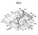
- Fig. 2 is a perspective view illustrating the arrangement of a lens processing section disposed in the casing of the main body 1.
- a carriage section 700 is mounted on a base 10, and a subject lens LE clamped by a pair of lens rotation shafts (lens chuck shafts) 702L and 702R of a carriage 701 is ground by a group of abrasive wheels 602 attached to an abrasive wheel rotating shaft 601.
- the group of abrasive wheels 602 include a rough abrasive wheel 602a for plastic lenses, a rough abrasive wheel 602b for glass lenses, and a finishing abrasive wheel 602c for beveling processing and flat processing.
- the rotating shaft 601 is rotatably attached to the base 10 by a spindle 603.
- a pulley 604 is attached to an end of the rotating shaft 601, and is linked through a belt 605 to a pulley 607 which is attached to a rotating shaft of an abrasive-wheel rotating motor 606.
- a lens-shape measuring section 500 is provided in the rear of the carriage 701. As the lens-shape measuring section 500, not only one that is disclosed by Japanese patent publication No. 2000-317796, but also other conventional devices can be used.
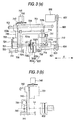
- Fig. 3 is a schematic diagram of essential portions of the carriage section 700
- Fig. 4 is a view, taken from the direction of arrow E in Fig. 2, of the carriage section 700.
- the carriage 701 is capable of rotating the lens LE while chucking it with two shafts 702L and 702R, and is rotatably slidable with respect to a carriage shaft 703 that is fixed to the base 10 and that extends in parallel to the shaft 601.
- a description will be given of a lens chuck mechanism and a lens rotating mechanism as well as an X-axis moving mechanism and a Y-axis moving mechanism of the carriage 701 by assuming that the direction in which the carriage 701 is moved in parallel to the abrasive-wheel rotating shaft 601 is the X axis, and the direction for changing the axis-to-axis distance between the shafts (702L, 702R) and the shaft 601 by the rotation of the carriage 701 is the Y axis.
- the shaft 702L and the shaft 702R are rotatably held coaxially by a left arm 701L and a right arm 701R, respectively, of the carriage 701.
- a chucking motor 710 is fixed to the center of the upper surface of the right arm 701R, and the rotation of a pulley 711 attached to a rotating shaft of the motor 710 rotates a feed screw 713, which is rotatably held inside the right arm 701R, by means of a belt 712.
- a feed nut 714 is moved in the axial direction by the rotation of the feed screw 713.
- the shaft 702R connected to the nut 714 can be moved in the axial direction, so that the lens LE is clamped by the shafts 702L and 702R.
- a rotatable block 720 for attaching a motor which is rotatable about the axis of the shaft 702L, is attached to a left-side end portion of the left arm 701L, and the chuck shaft 702L is passed through the block 720, a gear 721 being secured to the left end of the shaft 702L.
- a pulse motor 722 for lens rotation is fixed to the block 720, and as the motor 722 rotates the gear 721 through a gear 724, the rotation of the motor 720 is transmitted to the shaft 702L.
- a pulley 726 is attached to the shaft 702L inside the left arm 701L.
- the pulley 726 is linked by means of a timing belt 731a to a pulley 703a secured to a left end of a rotating shaft 728, which is held rotatably in the rear of the carriage 701. Further, a pulley 703b secured to a right end of the shaft 728 is linked by means of a timing belt 731b to a pulley 733 which is attached to the shaft 702R in such a manner as to be slidable in the axial direction of the shaft 702R inside the right arm 701R. By virtue of this arrangement, the shaft 702L and the shaft 702R are rotated synchronously.
- the shaft 703 is provided with a movable arm 740 which is slidable in its axial direction so that the arm 740 is movable in the X-axis direction (in the axial direction of the shaft 703) together with the carriage 701. Further, the arm 740 at its front portion is slidable on and along a guide shaft 741 that is secured to the base 10 in a parallel positional relation to the shaft 703.
- a rack 743 extending in parallel to the shaft 703 is attached to a rear portion of the arm 740, and this rack 743 meshes with a pinion 746 attached to a rotating shaft of a motor 745 for moving the carriage in the X-axis direction, the motor 745 being secured to the base 10.
- the motor 745 is able to move the carriage 701 together with the arm 740 in the axial direction (in the X-axis direction).
- a swingable block 750 is attached to the arm 740 in such a manner as to be rotatable about the axis La which is in alignment with the rotational center of the shaft 601.
- the distance from the center of the shaft 703 to the axis La and the distance from the center of the shaft 703 to the rotational center of the shaft (702L, 702R) are set to be identical.
- a Y-axis moving motor 751 is attached to the block 750, and the rotation of the motor 751 is transmitted by means of a pulley 752 and a belt 753 to a female screw 755 held rotatably in the block 750.
- a feed screw 756 is inserted in a threaded portion of the screw 755 in mesh therewith, and the screw 756 is moved vertically by the rotation of the screw 755.
- a guide block 760 which abuts against a lower end surface of the block 720 is fixed to an upper end of the screw 756, and the block 760 moves along two guide shafts 758a and 758b implanted on the block 750. Accordingly, as the block 760 is vertically moved together with the screw 756 by the rotation of the motor 751, it is possible to change the vertical position of the block 720 abutting against the block 760. As a result, the vertical position of the carriage 701 attached to the block 720 can be also changed (namely, the carriage 701 rotates about the shaft 703 to change the axis-to-axis distance between the shafts (702L, 702R) and the shaft 601).
- a spring 762 is stretched between the left arm 701L and the arm 740, so that the carriage 701 is constantly urged downward to impart processing pressure onto the lens LE. Although the downward urging force acts on the carriage 701, the downward movement of the carriage 701 is restricted such that the carriage 701 can only be lowered down to the position in which the block 720 abuts against the block 760.
- a sensor 764 for detecting an end of processing is attached to the block 720, and the sensor 764 detects the end of processing at each radius vector angle of the lens LE (each rotation angle) by detecting the position of a sensor plate 765 attached to the block 760.
- the shape of an eyeglass frame (or a template) for fitting is measured by the frame shape measuring device 2, and data thus obtained by the measurement are input to a data memory 161 by pressing a switch 421.
- a switch 421 By operating each switch of a switch panel section 420, an operator inputs necessary layout data such as the PD of a wearer and the height of an optical center, the material of the lens and a processing mode. The material of the lens is specified with a switch 426. If the necessary input is completed, the lens LE is chucked and processed through the shaft 702L and the shaft 702R.
- a control section 160 When the apparatus is operated by pressing a start switch 423, a control section 160 operates the lens shape measuring section 500 to measure the shapes of the front and rear surfaces of the lens. By the measurement, the thickness of a lens having a processing radius vector shape is obtained.
- the control section 160 operates each data on rough processing and finishing processing for each radius vector angle in accordance with a predetermined program based on the input data. In order of the rough processing and the finishing processing, the processing is automatically executed.
- the control section 160 drives the motor 745 such that the lens LE comes to a portion above the rough abrasive wheel 602b for glass, and thus moves the carriage 701. Based on rough processing data, then, the motor 751 is rotated to move the carriage 701 in a Y-axis direction and the lens LE is rotated by the motor 722 to carry out the rough processing. The movement of the carriage 701 in the Y-axis direction and the rotation of the lens LE are repeated until the end of the processing is detected by the sensor 764 over the whole radius vector angle of the lens LE. When the end of the processing is detected, the rough processing is completed.
- the finishing processing is successively executed automatically after the lens LE is removed from the rough abrasive wheel 602b.
- finishing processing for beveling after the lens LE is moved to a beveling groove portion of the finishing abrasive wheel 602c, the rotation of the lens LE and the movement of the carriage 701 in the Y-axis and X-axis directions are controlled based on the finishing processing data.
- the end of the processing is detected over the whole periphery of the lens LE through the sensor 764, the finishing processing is completed.
- the control section 160 measures times required from the start of the rough processing and the finishing processing by means of a counting function 162 provided therein. By the result of the measurement, a deterioration in the processing performance of each abrasive wheel is detected and a notice that dressing is required is given to an operator based on the result of the detection (see a flow chart of Fig. 6).
- the control section 160 causes the display 415 to display a message that the dressing is required for the rough abrasive wheel 602b. While the display is carried out when all processing including the finishing processing is completed, it may be performed when the time TR1 passes.
- a preset reference time TR1 for example, 5 minutes
- a preset reference time TF1 for example, 5 minutes
- a message that the dressing of the finishing abrasive wheel 602c is required is displayed on the display 415 after the processing is completed.
- the notice that the dressing is required may be given in a voice or an alarm by a voice generating section 165.
- a stop switch 424 is pressed to erase the display of the message, thereby carrying out the necessary dressing.
- Fig. 7 is a flow chart showing an operation to be carried out with such a structure.
- the control section 160 measures a time required from the start of the rough processing.
- a preset reference time TR2 for example, 10 minutes
- the carriage 701 is raised to separate the lens LE from the rough abrasive wheel 602b and the rotation of the lens LE and that of the abrasive wheel are stopped to interrupt the processing.
- a message that the processing is interrupted and the dressing of the rough abrasive wheel 602b is required is displayed on the display 415.
- the operator presses the switch 424 to erase the display of the message and sets a dress mode with a switch 425, thereby carrying out the dressing over the rough abrasive wheel 602b in a predetermined procedure.
- the switch 423 is pressed to restart the rough processing.
- the control section 160 measures the time required from the start of the finishing processing.
- a predetermined reference time TF2 for example, 10 minutes
- the processing to be carried out by the finishing abrasive wheel 602c is once interrupted.
- the switch 423 is pressed to restart the finishing processing.
- suitable times are predetermined in consideration of a time required for processing a thick lens (a lens having a large processing amount) in a state in which the diamond layers of the abrasive wheels 602b and 602c are normally arranged or an increase in the processing time with an increase in the number of lenses to be processed.
- TR2 and TF2 are set to be longer than TR1 and TF1 respectively, it is preferable that the lens should be completely processed and the dressing should be carried out before the measured times (processing times) TR2 and TF2 are reached. Therefore, it is possible to eliminate a great deal of time and labor of the reprocessing and a processing error caused by the reprocessing. It is effective to set the times TR2 and TF2 that the processing is once interrupted in that the processing time can be prevented from being excessively increased and a state in which the end of the processing is not detected can be avoided.
- the number of rotations of the lens LE can also be employed. The reason is that a time required for completing the processing and the number of rotations of the lens LE are almost proportional to each other in the case in which the lens LE is to be processed by a rotation at an almost equal speed.
- the number of rotations of the lens LE can be known from the number of rotations of the motor 722.
- the lens processing moreover, when the end of the processing is detected at a predetermined radius vector angle, the lens is rotated every minute angle and such an operation is repeated over the whole periphery. Thus, processing control is carried out. In this case, it is also possible to detect a deterioration in the processing performance of each abrasive wheel by a comparison of a time required for the end of the processing at an angle for the start of the processing with a preset reference time.
- the detection of a deterioration in the processing performance is not always carried out every time the lens is to be processed.
- a time required for the end of the processing for each lens or the number of rotations of the lens may be stored in a memory and, for example, a mean value of 10 lenses which is stored may be compared with a reference value.
- a parameter setting screen for changing a dress reference such as the time TR1 is called over the display 415 with the switch 426.
- Fig. 8 shows an example of the screen obtained at that time.
- control section 160 changes a decision reference value corresponding to the data on the lens thickness such that a reference time is increased if the lens thickness is great and is reduced if the lens thickness is small.
- Fig. 9 is a view illustrating another embodiment. Only different portions from those of the embodiment described above are shown and the structures shown according to the embodiment described above are employed for the same functions.
- an encoder 770 is fixed to a block 720' for motor attachment and a pinion 771 attached to a rotating shaft of the encoder 770 meshes with a rack formed on a guide shaft 758a' extended in parallel with a feed screw 756.
- the output of the encoder 770 is input to the control section 160 and the moving distance of elevation (Y-axis movement) of the carriage 701 is detected.
- a processing distance within a predetermined time at an angle for the start of the processing is compared with the reference processing distance. If the progress of the processing is slow, it is decided that the processing performance is deteriorated. In the case of a variant, furthermore, it is preferable that the operator can optionally change each reference value.
- control section 160 decides whether the material of the processed lens is glass or not.
- the control section 160 resets a count number.
Landscapes
- Engineering & Computer Science (AREA)
- Mechanical Engineering (AREA)
- Chemical & Material Sciences (AREA)
- Ceramic Engineering (AREA)
- Inorganic Chemistry (AREA)
- Grinding And Polishing Of Tertiary Curved Surfaces And Surfaces With Complex Shapes (AREA)
- Constituent Portions Of Griding Lathes, Driving, Sensing And Control (AREA)
Abstract
Description
- The present invention relates to an eyeglass lens processing apparatus for processing a periphery of an eyeglass lens.
- An eyeglass lens processing apparatus for processing a periphery of an eyeglass lens comprises a circular abrasive wheel (grindstone) having a diamond layer formed of a fine diamond particle and metal powder and serves to carry out processing by causing the periphery of the lens to come in contact with the rotating abrasive wheel by pressure.
- In such processing using the abrasive wheel, if a large number of lenses are processed, the diamond particle slips off or is worn away or clogged so that the processing performance of the abrasive wheel is deteriorated and a time required for processing the lens is increased. In such a case, generally, dressing is carried out through a dressing bar in order to arrange the diamond layer.
- However, it is difficult for an operator to carry out the dressing in a proper timing. More specifically, there is a problem in that it is hard for the operator to decide whether or not the processing time is increased and when the dressing is to be carried out.
- In consideration of the drawbacks of the conventional apparatus, it is a technological object of the invention to provide an eyeglass lens processing apparatus capable of easily managing a time that the dressing is to be carried out over an abrasive wheel.
- In order to attain the object, the invention has the following structure.
- (1) An eyeglass lens processing apparatus for
processing a periphery of an eyeglass lens, comprising:
- lens rotating means having rotating shafts for holding and rotating the lens;
- an abrasive wheel;
- abrasive wheel state detecting means for detecting a lowered processing performance of the abrasive wheel; and
- notifying means for notifying that dressing for the abrasive wheel is required based on a result of detection by the abrasive wheel state detecting means.
- (2) The eyeglass lens processing apparatus according
to (1), further comprising:
- processing state detecting means for detecting a state of processing for the lens; and wherein the abrasive wheel state detecting means detects the lowered processing performance of the abrasive wheel based on a result of comparison between the detected state of processing and a predetermined reference.
- (3) The eyeglass lens processing apparatus according
to (2), wherein:
- the processing state detecting means detects a processing time from a start of processing; and
- the abrasive wheel state detecting means detects the lowered processing performance of the abrasive wheel in case that the detected processing time exceeds a predetermined reference processing time.
- (4) The eyeglass lens processing apparatus according
to (2), wherein:
- the processing state detecting means detects an end of processing over the entire periphery of the lens or at a predetermined rotation angle of the lens; and
- the abrasive wheel state detecting means detects the lowered processing performance of the abrasive wheel in case that the end of processing is not detected within a predetermined reference processing time.
- (5) The eyeglass lens processing apparatus according
to (2), wherein:
- the processing state detecting means detects a number of lens rotation from a start of processing; and
- the abrasive wheel state detecting means detects the lowered processing performance of the abrasive wheel in case that the detected number of lens rotation exceeds a predetermined reference number of lens rotation.
- (6) The eyeglass lens processing apparatus according
to (2), wherein:
- the processing state detecting means detects an end of processing over the entire periphery of the lens or at a predetermined rotation angle of the lens; and
- the abrasive wheel state detecting means detects the lowered processing performance of the abrasive wheel in case that the end of processing is not detected within a predetermined reference number of lens rotation.
- (7) The eyeglass lens processing apparatus according
to (2), wherein:
- the processing state detecting means detects an amount of processing at a predetermined rotation angle of the lens; and
- the abrasive wheel state detecting means detects the lowered processing performance of the abrasive wheel in case that the amount of processing detected within a predetermined processing time or a predetermined number of lens rotation does not meet a predetermined reference amount of processing.
- (8) The eyeglass lens processing apparatus according
to (2), further comprising:
- changing means for changing a value of the reference.
- (9) The eyeglass lens processing apparatus according
to (8), further comprising:
- lens thickness input means for inputting a thickness of the lens; and wherein the changing means changes the reference value based on the inputted lens thickness.
- (10) The eyeglass lens processing apparatus according
to (2), further comprising:
- lens material input means for inputting a material of the lens to be processed; and wherein the processing state detecting means detects the state of processing for the lens only in case that a glass is inputted as the material.
- (11) The eyeglass lens processing apparatus according
to (2), wherein:
- the processing state detecting means detects the states of processing for a plurality of lenses; and
- the abrasive wheel state detecting means detects the lowered processing performance of the abrasive wheel based on a result of comparison between an average of the detected states of processing and the predetermined reference.
- (12) The eyeglass lens processing apparatus according
to (1), further comprising:
- processing control means for controlling processing for the lens based on a result of detection by the abrasive wheel state detecting means.
- (13) The eyeglass lens processing apparatus according
to (12), further comprising:
- processing state detecting means for detecting a state of processing for the lens; wherein the abrasive wheel state detecting means detects the lowered processing performance of the abrasive wheel based on a result of comparison between the detected state of processing and predetermined first and second references; and
- (14) The eyeglass lens processing apparatus according
to (1), wherein:
- the abrasive wheel includes a rough processing abrasive wheel and finish processing abrasive wheel; and
- the notifying means gives a notification regarding the rough processing abrasive wheel and a notification regarding the finish processing abrasive wheel independently of each other.
- (15) An eyeglass lens processing apparatus for
processing a periphery of an eyeglass lens, comprising:
- an abrasive wheel;
- counting means for counting a number of lenses which have been processed; and
- notifying means for notifying that dressing for the abrasive wheel is required in case that the counted number of lenses exceed a predetermined reference number.
- (16) The eyeglass lens processing apparatus according
to (15), further comprising:
- lens material input means for inputting a material of the lens to be processed; and wherein the counting means only counts the number of the processed lenses, each being inputted as a glass by the input means.
-
- The present disclosure relates to the subject matter contained in Japanese patent application No. 2001-433 (filed on January 15, 2001), which is expressly incorporated herein by reference in its entirety.
-
- Fig. 1 is a view showing a structure of the appearance of an eyeglass lens processing apparatus according to the invention;
- Fig. 2 is a perspective view showing a schematic structure of a processing section provided in a housing of an apparatus body;
- Fig. 3 is a view showing a schematic structure of a main part of a carriage section;
- Fig. 4 is a view showing the carriage section seen in a direction of E in Fig. 2;
- Fig. 5 is a block diagram showing a control system of the apparatus;
- Fig. 6 is a flowchart for explaining an operation for detecting a deterioration in the processing performance of each abrasive wheel;
- Fig. 7 is a flow chart for explaining an operation for temporarily interrupting the processing;
- Fig. 8 is a diagram showing an example of a screen obtained when each reference time for message display and processing stop are to be changed; and
- Fig. 9 is a view illustrating another embodiment.
-
- Hereafter, a description will be given of an embodiment of the invention. Fig. 1 is a diagram illustrating the external configuration of an eyeglass-lens processing apparatus in accordance with the invention. An eyeglass-frame-
shape measuring device 2 is incorporated in an upper right-hand rear portion of amain body 1 of the apparatus. As the frame-shape measuring device 2, ones that disclosed in USP 5,228,242, 5,333,412, USP5,347,762 (Re. 35,898) and so on, the assignee of which is the same as the present application, can be used. Aswitch panel section 410 having switches for operating the frame-shape measuring device 2 and adisplay 415 for displaying processing information and the like are disposed in front of the frame-shape measuring device 2. Further,reference numeral 420 denotes a switch panel section having various switches for inputting processing conditions and the like and for giving instructions for processing, and numeral 402 denotes an openable window for a processing chamber. - Fig. 2 is a perspective view illustrating the arrangement of a lens processing section disposed in the casing of the
main body 1. Acarriage section 700 is mounted on abase 10, and a subject lens LE clamped by a pair of lens rotation shafts (lens chuck shafts) 702L and 702R of acarriage 701 is ground by a group ofabrasive wheels 602 attached to an abrasive wheelrotating shaft 601. The group ofabrasive wheels 602 include a roughabrasive wheel 602a for plastic lenses, a roughabrasive wheel 602b for glass lenses, and a finishingabrasive wheel 602c for beveling processing and flat processing. Therotating shaft 601 is rotatably attached to thebase 10 by aspindle 603. Apulley 604 is attached to an end of therotating shaft 601, and is linked through abelt 605 to apulley 607 which is attached to a rotating shaft of an abrasive-wheelrotating motor 606. A lens-shape measuring section 500 is provided in the rear of thecarriage 701. As the lens-shape measuring section 500, not only one that is disclosed by Japanese patent publication No. 2000-317796, but also other conventional devices can be used. - Referring to Figs. 2, 3, and 4, a description will be given of the construction of the
carriage section 700. Fig. 3 is a schematic diagram of essential portions of thecarriage section 700, and Fig. 4 is a view, taken from the direction of arrow E in Fig. 2, of thecarriage section 700. - The
carriage 701 is capable of rotating the lens LE while chucking it with twoshafts carriage shaft 703 that is fixed to thebase 10 and that extends in parallel to theshaft 601. Hereafter, a description will be given of a lens chuck mechanism and a lens rotating mechanism as well as an X-axis moving mechanism and a Y-axis moving mechanism of thecarriage 701 by assuming that the direction in which thecarriage 701 is moved in parallel to the abrasive-wheelrotating shaft 601 is the X axis, and the direction for changing the axis-to-axis distance between the shafts (702L, 702R) and theshaft 601 by the rotation of thecarriage 701 is the Y axis. - The
shaft 702L and theshaft 702R are rotatably held coaxially by aleft arm 701L and a right arm 701R, respectively, of thecarriage 701. A chuckingmotor 710 is fixed to the center of the upper surface of the right arm 701R, and the rotation of apulley 711 attached to a rotating shaft of themotor 710 rotates afeed screw 713, which is rotatably held inside the right arm 701R, by means of abelt 712. Afeed nut 714 is moved in the axial direction by the rotation of thefeed screw 713. As a result, theshaft 702R connected to thenut 714 can be moved in the axial direction, so that the lens LE is clamped by theshafts - A
rotatable block 720 for attaching a motor, which is rotatable about the axis of theshaft 702L, is attached to a left-side end portion of theleft arm 701L, and thechuck shaft 702L is passed through theblock 720, agear 721 being secured to the left end of theshaft 702L. Apulse motor 722 for lens rotation is fixed to theblock 720, and as themotor 722 rotates thegear 721 through agear 724, the rotation of themotor 720 is transmitted to theshaft 702L. Apulley 726 is attached to theshaft 702L inside theleft arm 701L. Thepulley 726 is linked by means of atiming belt 731a to apulley 703a secured to a left end of arotating shaft 728, which is held rotatably in the rear of thecarriage 701. Further, apulley 703b secured to a right end of theshaft 728 is linked by means of atiming belt 731b to apulley 733 which is attached to theshaft 702R in such a manner as to be slidable in the axial direction of theshaft 702R inside the right arm 701R. By virtue of this arrangement, theshaft 702L and theshaft 702R are rotated synchronously. - The
shaft 703 is provided with amovable arm 740 which is slidable in its axial direction so that thearm 740 is movable in the X-axis direction (in the axial direction of the shaft 703) together with thecarriage 701. Further, thearm 740 at its front portion is slidable on and along aguide shaft 741 that is secured to the base 10 in a parallel positional relation to theshaft 703. Arack 743 extending in parallel to theshaft 703 is attached to a rear portion of thearm 740, and thisrack 743 meshes with apinion 746 attached to a rotating shaft of amotor 745 for moving the carriage in the X-axis direction, themotor 745 being secured to thebase 10. By virtue of the above-described arrangement, themotor 745 is able to move thecarriage 701 together with thearm 740 in the axial direction (in the X-axis direction). - As shown in Fig. 3(b), a
swingable block 750 is attached to thearm 740 in such a manner as to be rotatable about the axis La which is in alignment with the rotational center of theshaft 601. The distance from the center of theshaft 703 to the axis La and the distance from the center of theshaft 703 to the rotational center of the shaft (702L, 702R) are set to be identical. A Y-axis moving motor 751 is attached to theblock 750, and the rotation of themotor 751 is transmitted by means of apulley 752 and abelt 753 to afemale screw 755 held rotatably in theblock 750. Afeed screw 756 is inserted in a threaded portion of thescrew 755 in mesh therewith, and thescrew 756 is moved vertically by the rotation of thescrew 755. - A
guide block 760 which abuts against a lower end surface of theblock 720 is fixed to an upper end of thescrew 756, and theblock 760 moves along twoguide shafts block 750. Accordingly, as theblock 760 is vertically moved together with thescrew 756 by the rotation of themotor 751, it is possible to change the vertical position of theblock 720 abutting against theblock 760. As a result, the vertical position of thecarriage 701 attached to theblock 720 can be also changed (namely, thecarriage 701 rotates about theshaft 703 to change the axis-to-axis distance between the shafts (702L, 702R) and the shaft 601). Aspring 762 is stretched between theleft arm 701L and thearm 740, so that thecarriage 701 is constantly urged downward to impart processing pressure onto the lens LE. Although the downward urging force acts on thecarriage 701, the downward movement of thecarriage 701 is restricted such that thecarriage 701 can only be lowered down to the position in which theblock 720 abuts against theblock 760. Asensor 764 for detecting an end of processing is attached to theblock 720, and thesensor 764 detects the end of processing at each radius vector angle of the lens LE (each rotation angle) by detecting the position of asensor plate 765 attached to theblock 760. - The operation of the apparatus described above will be explained with reference to a block diagram showing a control system in Fig. 5. First of all, the whole processing operation of the apparatus will be described. Herein it is assumed that a glass lens is processed.
- The shape of an eyeglass frame (or a template) for fitting is measured by the frame
shape measuring device 2, and data thus obtained by the measurement are input to adata memory 161 by pressing aswitch 421. By operating each switch of aswitch panel section 420, an operator inputs necessary layout data such as the PD of a wearer and the height of an optical center, the material of the lens and a processing mode. The material of the lens is specified with aswitch 426. If the necessary input is completed, the lens LE is chucked and processed through theshaft 702L and theshaft 702R. - When the apparatus is operated by pressing a
start switch 423, acontrol section 160 operates the lensshape measuring section 500 to measure the shapes of the front and rear surfaces of the lens. By the measurement, the thickness of a lens having a processing radius vector shape is obtained. When the shape of the lens is obtained, thecontrol section 160 operates each data on rough processing and finishing processing for each radius vector angle in accordance with a predetermined program based on the input data. In order of the rough processing and the finishing processing, the processing is automatically executed. - The
control section 160 drives themotor 745 such that the lens LE comes to a portion above the roughabrasive wheel 602b for glass, and thus moves thecarriage 701. Based on rough processing data, then, themotor 751 is rotated to move thecarriage 701 in a Y-axis direction and the lens LE is rotated by themotor 722 to carry out the rough processing. The movement of thecarriage 701 in the Y-axis direction and the rotation of the lens LE are repeated until the end of the processing is detected by thesensor 764 over the whole radius vector angle of the lens LE. When the end of the processing is detected, the rough processing is completed. - When the rough processing is completed, the finishing processing is successively executed automatically after the lens LE is removed from the rough
abrasive wheel 602b. In the case of finishing processing for beveling, after the lens LE is moved to a beveling groove portion of the finishingabrasive wheel 602c, the rotation of the lens LE and the movement of thecarriage 701 in the Y-axis and X-axis directions are controlled based on the finishing processing data. When the end of the processing is detected over the whole periphery of the lens LE through thesensor 764, the finishing processing is completed. - By repeating such processing, a large number of lenses are processed. In the rough
abrasive wheel 602b and the finishingabrasive wheel 602c, consequently, processing performance is deteriorated due to slip-off or wear of the diamond particle so that a time required for processing the lens is gradually increased. Thecontrol section 160 measures times required from the start of the rough processing and the finishing processing by means of acounting function 162 provided therein. By the result of the measurement, a deterioration in the processing performance of each abrasive wheel is detected and a notice that dressing is required is given to an operator based on the result of the detection (see a flow chart of Fig. 6). - During the rough processing, when the measured time for the rough processing passes a preset reference time TR1 (for example, 5 minutes) (when the end of the processing of the whole periphery is not detected by the
sensor 764 even if the time TR1 passes), thecontrol section 160 causes thedisplay 415 to display a message that the dressing is required for the roughabrasive wheel 602b. While the display is carried out when all processing including the finishing processing is completed, it may be performed when the time TR1 passes. - Similarly, when the measured time for the finishingprocessing passes a preset reference time TF1 (for example, 5 minutes) (when the end of the processing of the whole periphery is not detected by the
sensor 764 even if the time TF1 passes), in the finishing processing, a message that the dressing of the finishingabrasive wheel 602c is required is displayed on thedisplay 415 after the processing is completed. - In addition to the display of the message, the notice that the dressing is required may be given in a voice or an alarm by a
voice generating section 165. - By the notice, the operator can precisely know a time that the dressing is required for the respective abrasive wheels. After the notice of each dressing is displayed on the
display 415, astop switch 424 is pressed to erase the display of the message, thereby carrying out the necessary dressing. - When the processing time is increased, moreover, the processing may be once interrupted to carry out the dressing and may be then restarted. Fig. 7 is a flow chart showing an operation to be carried out with such a structure. The
control section 160 measures a time required from the start of the rough processing. When the measured time for the rough processing exceeds a preset reference time TR2 (for example, 10 minutes) (when the end of the processing of the whole periphery is not detected by thesensor 764 even if the time TR2 is reached), thecarriage 701 is raised to separate the lens LE from the roughabrasive wheel 602b and the rotation of the lens LE and that of the abrasive wheel are stopped to interrupt the processing. At the same time, a message that the processing is interrupted and the dressing of the roughabrasive wheel 602b is required is displayed on thedisplay 415. When the processing is interrupted, the operator presses theswitch 424 to erase the display of the message and sets a dress mode with aswitch 425, thereby carrying out the dressing over the roughabrasive wheel 602b in a predetermined procedure. Then, theswitch 423 is pressed to restart the rough processing. - Also in the finishing processing, similarly, the
control section 160 measures the time required from the start of the finishing processing. When the measured time for the finishing processing exceeds a predetermined reference time TF2 (for example, 10 minutes) (when the end of the processing of the whole periphery is not detected by thesensor 764 even if the time TF2 is reached), the processing to be carried out by the finishingabrasive wheel 602c is once interrupted. After the finishing abrasive wheel 302c is subjected to the dressing, theswitch 423 is pressed to restart the finishing processing. - For the times TR1 and TF1, suitable times are predetermined in consideration of a time required for processing a thick lens (a lens having a large processing amount) in a state in which the diamond layers of the
abrasive wheels - Moreover, while the times TR2 and TF2 required for deciding whether or not the processing is temporarily interrupted may be equal to the times TR1 and TF1 for the message display, it is advantageous that the times TR2 and TF2 are set to be longer than the times TR1 and TF1. More specifically, in the case in which TR2 = TR1 and TF2 = TF1 are set, the processing is always interrupted temporarily if it is decided that the necessary time for the dressing arrives. Consequently, a great deal of time and labor is taken for reprocessing and a processing error is apt to be made. On the other hand, if TR2 and TF2 are set to be longer than TR1 and TF1 respectively, it is preferable that the lens should be completely processed and the dressing should be carried out before the measured times (processing times) TR2 and TF2 are reached. Therefore, it is possible to eliminate a great deal of time and labor of the reprocessing and a processing error caused by the reprocessing. It is effective to set the times TR2 and TF2 that the processing is once interrupted in that the processing time can be prevented from being excessively increased and a state in which the end of the processing is not detected can be avoided.
- While the reference for detecting a deterioration in the processing performance of the abrasive wheel is managed by the time in the embodiment, the number of rotations of the lens LE can also be employed. The reason is that a time required for completing the processing and the number of rotations of the lens LE are almost proportional to each other in the case in which the lens LE is to be processed by a rotation at an almost equal speed. The number of rotations of the lens LE can be known from the number of rotations of the
motor 722. - In the lens processing, moreover, when the end of the processing is detected at a predetermined radius vector angle, the lens is rotated every minute angle and such an operation is repeated over the whole periphery. Thus, processing control is carried out. In this case, it is also possible to detect a deterioration in the processing performance of each abrasive wheel by a comparison of a time required for the end of the processing at an angle for the start of the processing with a preset reference time.
- Moreover, the detection of a deterioration in the processing performance is not always carried out every time the lens is to be processed. A time required for the end of the processing for each lens or the number of rotations of the lens may be stored in a memory and, for example, a mean value of 10 lenses which is stored may be compared with a reference value. Thus, it is possible to evaluate the deterioration in the processing performance of the abrasive wheel with an overall tendency.
- Moreover, it is advantageous for the operator to optionally change each reference value for deciding whether or not a notice for the promotion of the dressing is to be given and the processing is to be stopped. In the case in which the times TR1, TR2, TF1 and TF2 in the above example are to be changed, the following operation is carried out. First of all, a parameter setting screen for changing a dress reference such as the time TR1 is called over the
display 415 with theswitch 426. Fig. 8 shows an example of the screen obtained at that time. After acursor 450 is set to a parameter item to be changed withswitches cursor 450, a set time is changed with numeric variation switches 428a and 428b. Theswitch 426 is pressed again to get out of the parameter setting screen. Consequently, each reference time to be managed by thecontrol section 160 is updated. - Moreover, there is a tendency in which a thick lens has a long processing time and a thin lens has a short processing time. By utilizing data on a lens thickness obtained as a result of the measurement of the lens
shape measuring section 500, therefore, it is also possible to determine a decision reference of a deterioration in processing performance. For example, thecontrol section 160 changes a decision reference value corresponding to the data on the lens thickness such that a reference time is increased if the lens thickness is great and is reduced if the lens thickness is small. - Fig. 9 is a view illustrating another embodiment. Only different portions from those of the embodiment described above are shown and the structures shown according to the embodiment described above are employed for the same functions. In Fig. 9, an
encoder 770 is fixed to a block 720' for motor attachment and apinion 771 attached to a rotating shaft of theencoder 770 meshes with a rack formed on aguide shaft 758a' extended in parallel with afeed screw 756. The output of theencoder 770 is input to thecontrol section 160 and the moving distance of elevation (Y-axis movement) of thecarriage 701 is detected. - Description will be given to the detection of a deterioration in the processing performance of an abrasive wheel with such a structure. In the case in which the lens LE is processed by a rotation at an almost equal speed (particularly, rough processing), the output of the
encoder 770 obtained by processing the lens LE with one rotation is first stored every predetermined angle. Next, the output of theencoder 770 is obtained every equal angle when a second rotation is started. Consequently, a processing distance (a processing amount) for each angle is obtained from the first rotation to the second rotation. The processing distance (the processing amount) for each angle is compared with a predetermined reference processing distance (a reference processing amount). If the processing distance is equal to or smaller than the reference processing distance, it is decided that the processing performance is deteriorated. - Moreover, in the case in which the lens LE is to be rotated and processed after the end of the processing is detected for each lens rotating angle, a processing distance within a predetermined time at an angle for the start of the processing is compared with the reference processing distance. If the progress of the processing is slow, it is decided that the processing performance is deteriorated. In the case of a variant, furthermore, it is preferable that the operator can optionally change each reference value.
- As another variant, furthermore, it is also possible to give a notice of a time that the dressing is required for the rough
abrasive wheel 602b and the finishingabrasive wheel 602c depending on whether or not the number of processed glass lenses reaches a reference number. Based on the input of a material when setting the processing conditions, thecontrol section 160 decides whether the material of the processed lens is glass or not. When the operator executes an operation for erasing a message display in order to carry out the dressing, thecontrol section 160 resets a count number. - As described above, the invention can be variously changed and various changes are also included in the invention within the same technical thought.
- As described above, according to the invention, it is possible to easily manage the dressing time of an abrasive wheel.
wherein the processing control means stops the processing for the lens based on a result of comparison by the abrasive wheel state detecting means using either one of the first and second references.
Claims (16)
- An eyeglass lens processing apparatus for processing a periphery of an eyeglass lens, comprising:lens rotating means having rotating shafts for holding and rotating the lens;an abrasive wheel;abrasive wheel state detecting means for detecting a lowered processing performance of the abrasive wheel; andnotifying means for notifying that dressing for the abrasive wheel is required based on a result of detection by the abrasive wheel state detecting means.
- The eyeglass lens processing apparatus according to claim 1, further comprising:wherein the abrasive wheel state detecting means detects the lowered processing performance of the abrasive wheel based on a result of comparison between the detected state of processing and a predetermined reference.processing state detecting means for detecting a state of processing for the lens; and
- The eyeglass lens processing apparatus according to claim 2, wherein:the processing state detecting means detects a processing time from a start of processing; andthe abrasive wheel state detecting means detects the lowered processing performance of the abrasive wheel in case that the detected processing time exceeds apredetermined reference processing time.
- The eyeglass lens processing apparatus according to claim 2, wherein:the processing state detecting means detects an end of processing over the entire periphery of the lens or at a predetermined rotation angle of the lens; andthe abrasive wheel state detecting means detects the lowered processing performance of the abrasive wheel in case that the end of processing is not detected within a predetermined reference processing time.
- The eyeglass lens processing apparatus according to claim 2, wherein:the processing state detecting means detects a number of lens rotation from a start of processing; andthe abrasive wheel state detecting means detects the lowered processing performance of the abrasive wheel in case that the detected number of lens rotation exceeds a predetermined reference number of lens rotation.
- The eyeglass lens processing apparatus according to claim 2, wherein:the processing state detecting means detects an end of processing over the entire periphery of the lens or at a predetermined rotation angle of the lens; andthe abrasive wheel state detecting means detects the lowered processing performance of the abrasive wheel in case that the end of processing is not detected within a predetermined reference number of lens rotation.
- The eyeglass lens processing apparatus according to claim 2, wherein:the processing state detecting means detects an amount of processing at a predetermined rotation angle of the lens; andthe abrasive wheel state detecting means detects the lowered processing performance of the abrasive wheel in case that the amount of processing detected within a predetermined processing time or a predetermined number of lens rotation does not meet a predetermined reference amount of processing.
- The eyeglass lens processing apparatus according to claim 2, further comprising:changing means for changing a value of the reference.
- The eyeglass lens processing apparatus according to claim 8, further comprising:wherein the changing means changes the reference value based on the inputted lens thickness.lens thickness input means for inputting a thickness of the lens; and
- The eyeglass lens processing apparatus according to claim 2, further comprising:wherein the processing state detecting means detects the state of processing for the lens only in case that a glass is inputted as the material.lens material input means for inputting a material of the lens to be processed; and
- The eyeglass lens processing apparatus according to claim 2, wherein:the processing state detecting means detects the states of processing for a plurality of lenses; andthe abrasive wheel state detecting means detects the lowered processing performance of the abrasive wheel based on a result of comparison between an average of the detected states of processing and the predetermined reference.
- The eyeglass lens processing apparatus according to claim 1, further comprising:processing control means for controlling processing for the lens based on a result of detection by the abrasive wheel state detecting means.
- The eyeglass lens processing apparatus according to claim 12, further comprising:wherein the abrasive wheel state detecting means detects the lowered processing performance of the abrasive wheel based on a result of comparison between the detected state of processing and predetermined first and second references; andprocessing state detecting means for detecting a state of processing for the lens;
wherein the processing control means stops the processing for the lens based on a result of comparison by the abrasive wheel state detecting means using either one of the first and second references. - The eyeglass lens processing apparatus according to claim 1, wherein:the abrasive wheel includes a rough processing abrasive wheel and finish processing abrasive wheel; andthe notifying means gives a notification regarding the rough processing abrasive wheel and a notification regarding the finish processing abrasive wheel independently of each other.
- An eyeglass lens processing apparatus for processing a periphery of an eyeglass lens, comprising:an abrasive wheel;counting means for counting a number of lenses which have been processed; andnotifying means for notifying that dressing for the abrasive wheel is required in case that the counted number of lenses exceed a predetermined reference number.
- The eyeglass lens processing apparatus according to claim 15, further comprising:wherein the counting means only counts the number of the processed lenses, each being inputted as a glass by the input means.lens material input means for inputting a material of the lens to be processed; and
Applications Claiming Priority (2)
| Application Number | Priority Date | Filing Date | Title |
|---|---|---|---|
| JP2001000433 | 2001-01-05 | ||
| JP2001000433A JP4288012B2 (en) | 2001-01-05 | 2001-01-05 | Eyeglass lens processing equipment |
Publications (2)
| Publication Number | Publication Date |
|---|---|
| EP1221356A1 true EP1221356A1 (en) | 2002-07-10 |
| EP1221356B1 EP1221356B1 (en) | 2007-09-05 |
Family
ID=18869220
Family Applications (1)
| Application Number | Title | Priority Date | Filing Date |
|---|---|---|---|
| EP02000351A Expired - Lifetime EP1221356B1 (en) | 2001-01-05 | 2002-01-04 | Eyeglass lens processing apparatus |
Country Status (5)
| Country | Link |
|---|---|
| US (1) | US6592431B2 (en) |
| EP (1) | EP1221356B1 (en) |
| JP (1) | JP4288012B2 (en) |
| DE (1) | DE60222192T2 (en) |
| ES (1) | ES2292646T3 (en) |
Cited By (1)
| Publication number | Priority date | Publication date | Assignee | Title |
|---|---|---|---|---|
| EP3957452A1 (en) * | 2020-08-17 | 2022-02-23 | Nidek Co., Ltd | Method of processing information for machining an eyeglass lens, eyeglass lens machining apparatus, and computer program |
Families Citing this family (7)
| Publication number | Priority date | Publication date | Assignee | Title |
|---|---|---|---|---|
| JP4267228B2 (en) * | 2001-12-03 | 2009-05-27 | 株式会社トプコン | Lens frame shape measuring device |
| JP4290673B2 (en) * | 2005-04-28 | 2009-07-08 | 株式会社ニデック | Glasses lens peripheral processing method |
| JP4895656B2 (en) | 2006-04-03 | 2012-03-14 | 株式会社ニデック | Whetstone dressing method and whetstone dressing apparatus for eyeglass lens peripheral edge processing apparatus |
| JP4975469B2 (en) * | 2007-02-02 | 2012-07-11 | 株式会社ニデック | Eyeglass lens processing equipment |
| CA2735704C (en) * | 2008-08-29 | 2020-05-05 | Nikon-Essilor Co., Ltd. | Lens processing management system |
| WO2012045412A1 (en) * | 2010-10-04 | 2012-04-12 | Schneider Gmbh & Co. Kg | Apparatus and method for working an optical lens and also a transporting container for optical lenses |
| JP6236787B2 (en) | 2013-01-17 | 2017-11-29 | 株式会社ニデック | Eyeglass lens processing equipment |
Citations (4)
| Publication number | Priority date | Publication date | Assignee | Title |
|---|---|---|---|---|
| US4555873A (en) * | 1981-03-30 | 1985-12-03 | Energy-Adaptive Grinding, Inc. | Method and apparatus for wheel conditioning in a grinding machine |
| EP0566853A2 (en) * | 1992-03-26 | 1993-10-27 | Toyoda Koki Kabushiki Kaisha | Method and apparatus for dressing a grinding wheel |
| EP0839604A1 (en) * | 1996-10-31 | 1998-05-06 | Nidek Co., Ltd. | Apparatus and method for grinding eyeglass lenses |
| EP0960689A1 (en) * | 1998-05-29 | 1999-12-01 | Nidek Co., Ltd. | Eyeglass lens grinding apparatus |
Family Cites Families (10)
| Publication number | Priority date | Publication date | Assignee | Title |
|---|---|---|---|---|
| CH651773A5 (en) * | 1983-03-31 | 1985-10-15 | Comadur Sa | PROCESS FOR FORMING A CONVERGENT LENS IN A PLATE OF TRANSPARENT MINERAL MATERIAL. |
| JPH02109671A (en) * | 1988-10-20 | 1990-04-23 | Olympus Optical Co Ltd | Lens grinding machine and lens working method |
| JPH085011B2 (en) * | 1989-07-10 | 1996-01-24 | オリンパス光学工業株式会社 | Grinding machine |
| JP3011526B2 (en) | 1992-02-04 | 2000-02-21 | 株式会社ニデック | Lens peripheral processing machine and lens peripheral processing method |
| FR2691663B1 (en) | 1992-05-26 | 1996-10-11 | Essilor Int | METHOD FOR REDEIVING GRINDING WHEELS, DISC AND MACHINE FOR ITS IMPLEMENTATION. |
| JPH0647664A (en) | 1992-07-31 | 1994-02-22 | Nikon Corp | Whetstone dressing device and dressing member used therefor |
| JPH0929632A (en) | 1995-07-17 | 1997-02-04 | Topcon Corp | Lens grinding wheel dressing method and dressing apparatus used therefor |
| DE19750428B4 (en) * | 1997-11-14 | 2007-06-21 | Optotech Optikmaschinen Gmbh | Method and device for processing lenses |
| JP3730410B2 (en) | 1998-05-29 | 2006-01-05 | 株式会社ニデック | Eyeglass lens processing equipment |
| JP2000015549A (en) | 1998-06-30 | 2000-01-18 | Nidek Co Ltd | Spectacle lens machining device |
-
2001
- 2001-01-05 JP JP2001000433A patent/JP4288012B2/en not_active Expired - Lifetime
-
2002
- 2002-01-03 US US10/034,074 patent/US6592431B2/en not_active Expired - Lifetime
- 2002-01-04 ES ES02000351T patent/ES2292646T3/en not_active Expired - Lifetime
- 2002-01-04 DE DE60222192T patent/DE60222192T2/en not_active Expired - Lifetime
- 2002-01-04 EP EP02000351A patent/EP1221356B1/en not_active Expired - Lifetime
Patent Citations (4)
| Publication number | Priority date | Publication date | Assignee | Title |
|---|---|---|---|---|
| US4555873A (en) * | 1981-03-30 | 1985-12-03 | Energy-Adaptive Grinding, Inc. | Method and apparatus for wheel conditioning in a grinding machine |
| EP0566853A2 (en) * | 1992-03-26 | 1993-10-27 | Toyoda Koki Kabushiki Kaisha | Method and apparatus for dressing a grinding wheel |
| EP0839604A1 (en) * | 1996-10-31 | 1998-05-06 | Nidek Co., Ltd. | Apparatus and method for grinding eyeglass lenses |
| EP0960689A1 (en) * | 1998-05-29 | 1999-12-01 | Nidek Co., Ltd. | Eyeglass lens grinding apparatus |
Cited By (1)
| Publication number | Priority date | Publication date | Assignee | Title |
|---|---|---|---|---|
| EP3957452A1 (en) * | 2020-08-17 | 2022-02-23 | Nidek Co., Ltd | Method of processing information for machining an eyeglass lens, eyeglass lens machining apparatus, and computer program |
Also Published As
| Publication number | Publication date |
|---|---|
| DE60222192D1 (en) | 2007-10-18 |
| JP2002205251A (en) | 2002-07-23 |
| US6592431B2 (en) | 2003-07-15 |
| ES2292646T3 (en) | 2008-03-16 |
| EP1221356B1 (en) | 2007-09-05 |
| JP4288012B2 (en) | 2009-07-01 |
| US20020115381A1 (en) | 2002-08-22 |
| DE60222192T2 (en) | 2008-06-05 |
Similar Documents
| Publication | Publication Date | Title |
|---|---|---|
| JP5405720B2 (en) | Eyeglass lens processing equipment | |
| JP5073345B2 (en) | Eyeglass lens processing equipment | |
| EP1266722B1 (en) | Eyeglass lens processing apparatus | |
| EP1155775B1 (en) | Eyeglass lens processing apparatus | |
| EP1310326A1 (en) | Eyeglass lens processing apparatus | |
| EP2191935B1 (en) | Eyeglass lens processing apparatus for processing periphery of eyeglass lens | |
| EP1510290B1 (en) | Eyeglass lens processing apparatus | |
| KR101415475B1 (en) | Eyeglass lens processing apparatus | |
| EP1221356B1 (en) | Eyeglass lens processing apparatus | |
| JP5265127B2 (en) | Eyeglass lens processing equipment | |
| EP1199134B1 (en) | Lens grinding apparatus | |
| EP1852216B1 (en) | Eyeglass lens processing apparatus | |
| JP3602303B2 (en) | Eyeglass lens grinding machine | |
| EP1852217B1 (en) | Facetting area setting device and eyeglass lens processing apparatus | |
| JP4431413B2 (en) | Eyeglass lens processing equipment | |
| JP2001252854A (en) | Dressing apparatus and lens grinding apparatus having the same | |
| EP1366857B1 (en) | Eyeglass lens processing apparatus | |
| JPH0929632A (en) | Lens grinding wheel dressing method and dressing apparatus used therefor | |
| JP4036942B2 (en) | Eyeglass lens grinding device | |
| JPH11156685A (en) | Spectacle lens grinding device |
Legal Events
| Date | Code | Title | Description |
|---|---|---|---|
| PUAI | Public reference made under article 153(3) epc to a published international application that has entered the european phase |
Free format text: ORIGINAL CODE: 0009012 |
|
| AK | Designated contracting states |
Kind code of ref document: A1 Designated state(s): AT BE CH CY DE DK ES FI FR GB GR IE IT LI LU MC NL PT SE TR |
|
| AX | Request for extension of the european patent |
Free format text: AL;LT;LV;MK;RO;SI |
|
| 17P | Request for examination filed |
Effective date: 20021121 |
|
| AKX | Designation fees paid |
Designated state(s): DE ES FR GB |
|
| 17Q | First examination report despatched |
Effective date: 20030311 |
|
| GRAP | Despatch of communication of intention to grant a patent |
Free format text: ORIGINAL CODE: EPIDOSNIGR1 |
|
| GRAS | Grant fee paid |
Free format text: ORIGINAL CODE: EPIDOSNIGR3 |
|
| GRAA | (expected) grant |
Free format text: ORIGINAL CODE: 0009210 |
|
| AK | Designated contracting states |
Kind code of ref document: B1 Designated state(s): DE ES FR GB |
|
| REG | Reference to a national code |
Ref country code: GB Ref legal event code: FG4D |
|
| REF | Corresponds to: |
Ref document number: 60222192 Country of ref document: DE Date of ref document: 20071018 Kind code of ref document: P |
|
| ET | Fr: translation filed | ||
| REG | Reference to a national code |
Ref country code: ES Ref legal event code: FG2A Ref document number: 2292646 Country of ref document: ES Kind code of ref document: T3 |
|
| PLBE | No opposition filed within time limit |
Free format text: ORIGINAL CODE: 0009261 |
|
| STAA | Information on the status of an ep patent application or granted ep patent |
Free format text: STATUS: NO OPPOSITION FILED WITHIN TIME LIMIT |
|
| 26N | No opposition filed |
Effective date: 20080606 |
|
| PGFP | Annual fee paid to national office [announced via postgrant information from national office to epo] |
Ref country code: GB Payment date: 20081231 Year of fee payment: 8 |
|
| GBPC | Gb: european patent ceased through non-payment of renewal fee |
Effective date: 20100104 |
|
| PG25 | Lapsed in a contracting state [announced via postgrant information from national office to epo] |
Ref country code: GB Free format text: LAPSE BECAUSE OF NON-PAYMENT OF DUE FEES Effective date: 20100104 |
|
| PGFP | Annual fee paid to national office [announced via postgrant information from national office to epo] |
Ref country code: DE Payment date: 20130103 Year of fee payment: 12 |
|
| REG | Reference to a national code |
Ref country code: DE Ref legal event code: R119 Ref document number: 60222192 Country of ref document: DE |
|
| REG | Reference to a national code |
Ref country code: DE Ref legal event code: R119 Ref document number: 60222192 Country of ref document: DE Effective date: 20140801 |
|
| PG25 | Lapsed in a contracting state [announced via postgrant information from national office to epo] |
Ref country code: DE Free format text: LAPSE BECAUSE OF NON-PAYMENT OF DUE FEES Effective date: 20140801 |
|
| REG | Reference to a national code |
Ref country code: FR Ref legal event code: PLFP Year of fee payment: 14 |
|
| PGFP | Annual fee paid to national office [announced via postgrant information from national office to epo] |
Ref country code: ES Payment date: 20141211 Year of fee payment: 14 |
|
| PGFP | Annual fee paid to national office [announced via postgrant information from national office to epo] |
Ref country code: FR Payment date: 20150108 Year of fee payment: 14 |
|
| REG | Reference to a national code |
Ref country code: FR Ref legal event code: ST Effective date: 20160930 |
|
| PG25 | Lapsed in a contracting state [announced via postgrant information from national office to epo] |
Ref country code: FR Free format text: LAPSE BECAUSE OF NON-PAYMENT OF DUE FEES Effective date: 20160201 |
|
| REG | Reference to a national code |
Ref country code: ES Ref legal event code: FD2A Effective date: 20170224 |
|
| PG25 | Lapsed in a contracting state [announced via postgrant information from national office to epo] |
Ref country code: ES Free format text: LAPSE BECAUSE OF NON-PAYMENT OF DUE FEES Effective date: 20160105 |