EP1220835B1 - Process for the production of acrylonitrile using direct contact spray heat exchange in the absorber - Google Patents
Process for the production of acrylonitrile using direct contact spray heat exchange in the absorber Download PDFInfo
- Publication number
- EP1220835B1 EP1220835B1 EP99954877A EP99954877A EP1220835B1 EP 1220835 B1 EP1220835 B1 EP 1220835B1 EP 99954877 A EP99954877 A EP 99954877A EP 99954877 A EP99954877 A EP 99954877A EP 1220835 B1 EP1220835 B1 EP 1220835B1
- Authority
- EP
- European Patent Office
- Prior art keywords
- acrylonitrile
- reactor effluent
- absorption column
- column
- crude acrylonitrile
- Prior art date
- Legal status (The legal status is an assumption and is not a legal conclusion. Google has not performed a legal analysis and makes no representation as to the accuracy of the status listed.)
- Expired - Lifetime
Links
- NLHHRLWOUZZQLW-UHFFFAOYSA-N Acrylonitrile Chemical compound C=CC#N NLHHRLWOUZZQLW-UHFFFAOYSA-N 0.000 title claims abstract description 57
- 239000007921 spray Substances 0.000 title claims abstract description 27
- 238000000034 method Methods 0.000 title claims abstract description 21
- 238000004519 manufacturing process Methods 0.000 title claims abstract description 10
- 239000006096 absorbing agent Substances 0.000 title 1
- 238000010521 absorption reaction Methods 0.000 claims abstract description 39
- 238000011084 recovery Methods 0.000 claims abstract description 14
- QGZKDVFQNNGYKY-UHFFFAOYSA-N Ammonia Chemical compound N QGZKDVFQNNGYKY-UHFFFAOYSA-N 0.000 claims abstract description 12
- 239000007788 liquid Substances 0.000 claims abstract description 12
- 238000000746 purification Methods 0.000 claims abstract description 9
- 238000010791 quenching Methods 0.000 claims abstract description 9
- QQONPFPTGQHPMA-UHFFFAOYSA-N propylene Natural products CC=C QQONPFPTGQHPMA-UHFFFAOYSA-N 0.000 claims abstract description 7
- 125000004805 propylene group Chemical group [H]C([H])([H])C([H])([*:1])C([H])([H])[*:2] 0.000 claims abstract description 7
- 229910021529 ammonia Inorganic materials 0.000 claims abstract description 6
- QVGXLLKOCUKJST-UHFFFAOYSA-N atomic oxygen Chemical compound [O] QVGXLLKOCUKJST-UHFFFAOYSA-N 0.000 claims abstract description 6
- 239000001301 oxygen Substances 0.000 claims abstract description 6
- 229910052760 oxygen Inorganic materials 0.000 claims abstract description 6
- 239000003054 catalyst Substances 0.000 claims abstract description 5
- 239000012530 fluid Substances 0.000 claims description 10
- WEVYAHXRMPXWCK-UHFFFAOYSA-N Acetonitrile Chemical compound CC#N WEVYAHXRMPXWCK-UHFFFAOYSA-N 0.000 description 12
- XLYOFNOQVPJJNP-UHFFFAOYSA-N water Substances O XLYOFNOQVPJJNP-UHFFFAOYSA-N 0.000 description 9
- 239000007789 gas Substances 0.000 description 8
- 229920000642 polymer Polymers 0.000 description 6
- 238000012856 packing Methods 0.000 description 4
- 238000006243 chemical reaction Methods 0.000 description 3
- 238000004821 distillation Methods 0.000 description 3
- 230000008030 elimination Effects 0.000 description 2
- 238000003379 elimination reaction Methods 0.000 description 2
- 239000012535 impurity Substances 0.000 description 2
- GYCMBHHDWRMZGG-UHFFFAOYSA-N Methylacrylonitrile Chemical compound CC(=C)C#N GYCMBHHDWRMZGG-UHFFFAOYSA-N 0.000 description 1
- 230000006978 adaptation Effects 0.000 description 1
- 230000015572 biosynthetic process Effects 0.000 description 1
- 238000004140 cleaning Methods 0.000 description 1
- LELOWRISYMNNSU-UHFFFAOYSA-N hydrogen cyanide Chemical compound N#C LELOWRISYMNNSU-UHFFFAOYSA-N 0.000 description 1
- 238000005457 optimization Methods 0.000 description 1
- 239000002699 waste material Substances 0.000 description 1
Images
Classifications
-
- C—CHEMISTRY; METALLURGY
- C07—ORGANIC CHEMISTRY
- C07C—ACYCLIC OR CARBOCYCLIC COMPOUNDS
- C07C253/00—Preparation of carboxylic acid nitriles
- C07C253/32—Separation; Purification; Stabilisation; Use of additives
- C07C253/34—Separation; Purification
-
- C—CHEMISTRY; METALLURGY
- C07—ORGANIC CHEMISTRY
- C07C—ACYCLIC OR CARBOCYCLIC COMPOUNDS
- C07C253/00—Preparation of carboxylic acid nitriles
- C07C253/24—Preparation of carboxylic acid nitriles by ammoxidation of hydrocarbons or substituted hydrocarbons
- C07C253/26—Preparation of carboxylic acid nitriles by ammoxidation of hydrocarbons or substituted hydrocarbons containing carbon-to-carbon multiple bonds, e.g. unsaturated aldehydes
Definitions
- the present invention is directed to the manufacture of acrylonitrile.
- the present invention is directed to an improved process for the manufacture of acrylonitrile utilizing a fluid bed reactor.
- the process for manufacturing acrylonitrile in a fluid bed reactor has been practiced commercially since the early 1960's.
- the reactor effluent from the propylene ammoxidation reaction in a fluid bed reactor is passed through a quench column, absorption column and recovery stripper columns to purify and recover the acrylonitrile product.
- a water stream is used to absorb the product organics (acrylonitrile, acetonitrile and HCN) from the vapor stream in the absorption column.
- the product organics removed in the absorption column are then stripped from the water stream in the recovery stripper columns.
- the absorption column contains three sections: (1) a lower heat transfer zone where hot gases from the quench are cooled by direct heat exchange with cold water; (2) an absorption zone where organics in the reaction gases are absorbed into a chilled water (the resultant water, rich with organic product is called a "rich water”); and (3) an upper heat transfer zone where incoming water is cooled by direct exchange with the cold strip gas.
- the intemals for these three sections of the absorption column typically comprise refractionation trays or structured packing or random packing.
- the present invention is directed to an improved process for the manufacture and recovery of acrylonitrile which results in improved run time due to elimination of polymer fouling problems in the absorption column.
- the process of the present invention comprises reacting propylene, ammonia and oxygen in a reaction zone in the presence of a catalyst to produce a reactor effluent containing crude acrylonitrile, transferring the reactor effluent containing crude acrylonitrile to a quench column wherein the reactor effluent containing crude acrylonitrile is contacted with an aqueous stream to cool the reactor effluent, transferring the cooled reactor effluent containing the crude acrylonitrile to an absorption column wherein the reactor effluent containing the crude acrylonitrile is contacted with a second aqueous stream to separate and remove crude acrylonitrile as a bottom stream, transferring the bottom stream containing the crude acrylonitrile to a recovery column where the acrylonitrile is recovered, wherein the improvement comprises supplying the second aqueous stream to the absorption column by means of liquid spray
- the process for the manufacture of acrylonitrile comprises contacting the ammonia, oxygen-containing gas and propylene in the presence of a fluid bed catalyst in a fluid bed reactor.
- the spray nozzles are positioned in the bottom portion of the absorption column.
- the spray nozzles are positioned in the top heat transfer position of the absorption column.
- the spray nozzles are positioned throughout the absorption column.
- the invention can be applied to any recovery and purification for acrylonitrile and methacrylonitrile that has an absorption column wherein the product is transferred from the quench column to the absorption column prior to recovery and purification of the product acrylonitrile.
- the specific intermediate steps associated with the recovery and purification are not critical to the present invention and within the purview of anyone having ordinary skill in the art.
- distillation towers may be utilized in the purification of the crude acrylonitrile to produce acrylonitrile.
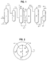
- propylene and ammonia are transferred to reactor 1 via line 2 and an oxygen-containing gas (typically, air) is supplied to the reactor via line 4.
- the propylene, ammonia and oxygen react in the reactor (preferably, a fluid bed reactor) in the presence of a fluid bed catalyst to produce acrylonitrile.
- the reactor effluent containing acrylonitrile is transferred from reactor 1 via line 3 to quench 5 wherein the reactor effluents are cooled by direct contact with an aqueous stream.
- the cooled reactor effluent is removed from quench 5 and enters absorption column 9 via line 7 wherein an aqueous stream contacts the cooled reactor effluent to remove the crude acrylonitrile (a crude acrylonitrile is intended to refer to acrylonitrile which is containing various impurities including co-products HCN and acetonitrile) present in the reactor effluent.
- the crude acrylonitrile is then transferred from the absorption column 9 via line 13 to recovery column 15 wherein the crude acrylonitrile is subjected to distillation to remove certain impurities and the crude acrylonitrile is transferred via line 23 to head column 25 where further distillation takes place to separate the acrylonitrile from the co-products (i.e.
- HCN and acetonitrile The recovered acrylonitrile is then removed from heads column 25 via line 27 and is further purified in product column 31. Purified acrylontrile is removed from product column 31 via line 35 and waste is recovered for recycle via line 33.
- Co-product HCN is usually recovered from line 29 of heads column 25.
- Co-product acetonitrile is usually recovered as a side stream (not shown) from recovery column 15.
- absorption column 9 is specifically adapted to provide a novel procedure for contacting the cooled reactor effluent gas containing acrylonitrile to remove the acrylonitrile from the reactor effluent.
- FIG 2 is a cross sectional view of absorption column 9 and shows a preferred embodiment of the present invention.
- the internal section of absorption column 9 contains a circular shaped grid having a cross bar 41.
- Grid 37 and cross bar 41 are adapted to have liquid spray nozzles 39 positioned about the circular grid 37 and cross bar 41 in such a manner that the aqueous spray coming from nozzles 39 encompasses the entire circumference of absorption column 39 allowing for complete contact of the aqueous spray with the cooled reactor effluent gas to remove the acrylonitrile as a bottom stream via line 13 ( Figure 1).
- the spacing between the liquid spray nozzles is from 0.91 m to 3.66 m (36 inches to 144 inches), preferably 1.22 m to 2.29 m (48 inches to 90 inches).
- the number of spray nozzles utilized in a column will depend on the size of the column with the objective being to ensure that the entire circumference of the column is covered.
- the number of nozzles utilized ranges from 7 to 10 depending on the size of the nozzle used.
- the actual configuration of the nozzles is not critical provided that substantially all of the circumference of the column is encompassed by the spray pattern emanating from the spray nozzles.
- Hollow cone or full cone liquid spray nozzles may be installed in the upper and/or lower heat transfer sections of the absorption column. It is a preferred embodiment of the present invention that multiple levels of hollow cone nozzles are installed with adequate spacing between the nozzles and levels to insure total coverage of the liquid spray over the full open area of the absorption column shell.
- Adequate pumped liquid circulation is introduced through the spray nozzles to accomplish the desired heat transfer in the upper and/or lower heat transfer section via direct contacting of the gas phase containing product acrylonitrile with the sprayed liquid.
- the pumped liquid may preferably be a slip stream of the absorption tower bottoms or a slip stream of the absorption tower side drawer and/or the absorption tower lean water and/or fresh make-up water to the absorption tower and/or process condensed from the quench.
- manual or automatic control valves are installed on the supply piping to each level of spray nozzles to allow adjustment of the flow rate to each level and optimization of heat transfer.
Landscapes
- Chemical & Material Sciences (AREA)
- Organic Chemistry (AREA)
- Organic Low-Molecular-Weight Compounds And Preparation Thereof (AREA)
- Physical Or Chemical Processes And Apparatus (AREA)
- Low-Molecular Organic Synthesis Reactions Using Catalysts (AREA)
- Extraction Or Liquid Replacement (AREA)
Abstract
Description
Claims (5)
- A process for manufacturing acrylonitrile comprising reacting propylene, ammonia and oxygen in a reactor zone in the presence of a catalyst to produce a reactor effluent containing crude acrylonitrile, transferring the reactor effluent containing crude acrylonitrile to a quench column wherein the reactor effluent containing crude acrylonitrile is contacted with a first aqueous stream to cool the reactor effluent, transferring the cooled reactor effluent containing the crude acrylonitrile to an absorption column wherein the reactor effluent containing crude acrylonitrile is contacted with a second aqueous stream to separate and remove the crude acrylonitrile as a bottom stream from the absorption column, transferring the bottom stream containing the crude acrylonitrile to a recovery and purification section where the acrylonitrile is recovered and purified, wherein the improvement comprises supplying the second aqueous stream to the absorption column by means of liquid spray nozzles.
- The process of claim 1 wherein the reactor zone comprises a fluid bed reactor.
- The process of claim 1 wherein the spray nozzles are positioned in the bottom portion of the absorption column.
- The process of claim 1 wherein the spray nozzles are positioned in the upper portion of the absorption column.
- The process of claim 1 wherein the spray nozzles are positioned throughout the absorption column.
Applications Claiming Priority (2)
| Application Number | Priority Date | Filing Date | Title |
|---|---|---|---|
| US09/078,789 US6002040A (en) | 1998-05-14 | 1998-05-14 | Reduced pressure drop in acrylonitrile absorber via direct contact spray heat exchange |
| PCT/US1999/023792 WO2001027075A1 (en) | 1998-05-14 | 1999-10-12 | Process for the production of acrylonitrile using direct contact spray heat exchange in the absorber |
Publications (2)
| Publication Number | Publication Date |
|---|---|
| EP1220835A1 EP1220835A1 (en) | 2002-07-10 |
| EP1220835B1 true EP1220835B1 (en) | 2004-04-14 |
Family
ID=26760942
Family Applications (1)
| Application Number | Title | Priority Date | Filing Date |
|---|---|---|---|
| EP99954877A Expired - Lifetime EP1220835B1 (en) | 1998-05-14 | 1999-10-12 | Process for the production of acrylonitrile using direct contact spray heat exchange in the absorber |
Country Status (11)
| Country | Link |
|---|---|
| US (1) | US6002040A (en) |
| EP (1) | EP1220835B1 (en) |
| JP (1) | JP2003511439A (en) |
| CN (1) | CN1373789A (en) |
| AT (1) | ATE264297T1 (en) |
| BR (1) | BR9917516A (en) |
| DE (1) | DE69916506T2 (en) |
| ES (1) | ES2220124T3 (en) |
| MX (1) | MXPA02003666A (en) |
| TR (1) | TR200200974T2 (en) |
| WO (1) | WO2001027075A1 (en) |
Cited By (1)
| Publication number | Priority date | Publication date | Assignee | Title |
|---|---|---|---|---|
| EP3388426A2 (en) | 2012-12-19 | 2018-10-17 | Sulfateq B.V. | Compounds for protection of cells |
Families Citing this family (4)
| Publication number | Priority date | Publication date | Assignee | Title |
|---|---|---|---|---|
| US6296739B1 (en) * | 1999-01-08 | 2001-10-02 | The Standard Oil Company | Operation of heads column |
| CN105985262A (en) * | 2015-03-06 | 2016-10-05 | 英尼奥斯欧洲股份公司 | Improved Acrylonitrile Manufacturing |
| JP6566035B2 (en) * | 2015-08-24 | 2019-08-28 | 株式会社島津製作所 | Preparative purification equipment |
| WO2018118580A1 (en) * | 2016-12-20 | 2018-06-28 | The Procter & Gamble Company | Method for separating and purifying polymers from reclaimed product |
Family Cites Families (8)
| Publication number | Priority date | Publication date | Assignee | Title |
|---|---|---|---|---|
| JPS5677249A (en) * | 1979-11-30 | 1981-06-25 | Asahi Chem Ind Co Ltd | Recovery of olefinic unsaturated nitrile |
| DE3236304C2 (en) * | 1982-09-30 | 1986-09-25 | Penzenskij zavod chimičeskogo mašinostroenija, Penza | Absorber with floating packing |
| WO1996023765A1 (en) * | 1995-01-31 | 1996-08-08 | Asahi Kasei Kogyo Kabushiki Kaisha | Process for producing acrylonitrile |
| JPH08231487A (en) * | 1995-02-28 | 1996-09-10 | Asahi Chem Ind Co Ltd | Production of acrylonitrile |
| US5629444A (en) * | 1996-06-06 | 1997-05-13 | The Standard Oil Company | Acrylonitrile recovery process |
| US5840955A (en) * | 1997-11-25 | 1998-11-24 | Sockell; Edward J. | Waste minimization and product recovery process |
| US5869730A (en) * | 1998-05-13 | 1999-02-09 | The Standard Oil Company | Oxidant reduction by manipulation and/or treatment of aqueous acrylonitrile process streams |
| US6107509A (en) * | 1999-03-31 | 2000-08-22 | The Standard Oil Company | Process for the recovery of acrylonitrile and methacrylontrile |
-
1998
- 1998-05-14 US US09/078,789 patent/US6002040A/en not_active Expired - Fee Related
-
1999
- 1999-08-06 CN CN99816937A patent/CN1373789A/en active Pending
- 1999-10-12 TR TR2002/00974T patent/TR200200974T2/en unknown
- 1999-10-12 BR BR9917516-9A patent/BR9917516A/en not_active IP Right Cessation
- 1999-10-12 JP JP2001530096A patent/JP2003511439A/en not_active Ceased
- 1999-10-12 EP EP99954877A patent/EP1220835B1/en not_active Expired - Lifetime
- 1999-10-12 WO PCT/US1999/023792 patent/WO2001027075A1/en not_active Ceased
- 1999-10-12 ES ES99954877T patent/ES2220124T3/en not_active Expired - Lifetime
- 1999-10-12 MX MXPA02003666A patent/MXPA02003666A/en not_active IP Right Cessation
- 1999-10-12 DE DE69916506T patent/DE69916506T2/en not_active Expired - Fee Related
- 1999-10-12 AT AT99954877T patent/ATE264297T1/en not_active IP Right Cessation
Cited By (1)
| Publication number | Priority date | Publication date | Assignee | Title |
|---|---|---|---|---|
| EP3388426A2 (en) | 2012-12-19 | 2018-10-17 | Sulfateq B.V. | Compounds for protection of cells |
Also Published As
| Publication number | Publication date |
|---|---|
| BR9917516A (en) | 2002-06-11 |
| ES2220124T3 (en) | 2004-12-01 |
| US6002040A (en) | 1999-12-14 |
| EP1220835A1 (en) | 2002-07-10 |
| DE69916506T2 (en) | 2004-08-19 |
| CN1373789A (en) | 2002-10-09 |
| MXPA02003666A (en) | 2003-05-23 |
| TR200200974T2 (en) | 2002-08-21 |
| WO2001027075A1 (en) | 2001-04-19 |
| JP2003511439A (en) | 2003-03-25 |
| DE69916506D1 (en) | 2004-05-19 |
| ATE264297T1 (en) | 2004-04-15 |
Similar Documents
| Publication | Publication Date | Title |
|---|---|---|
| JP2009102398A (en) | Waste minimization and product recovery process | |
| JP4664507B2 (en) | An improved method for the recovery of acrylonitrile and methacrylonitrile. | |
| US6002040A (en) | Reduced pressure drop in acrylonitrile absorber via direct contact spray heat exchange | |
| US6296739B1 (en) | Operation of heads column | |
| KR20010071471A (en) | Process for recovery of olefinically unsaturated nitriles | |
| WO1998017634A1 (en) | Process for purifying acrylonitrile | |
| EP1439167A1 (en) | Recycle of condensed quench overheads in a process for purifying acrylonitrile | |
| US5801266A (en) | Method for producing acrylonitrile | |
| US20090299087A1 (en) | Process for manufacturing unsaturated mononitriles to improve on-stream time and reduce fouling | |
| CN1153760C (en) | Process for production of acrylonitrile using direct contact spray heat exchange in absorber | |
| US6054603A (en) | Acrylonitrile recovery process | |
| RU2236400C2 (en) | Acrylonitrile manufacture process | |
| KR20020043607A (en) | Process for the production of acrylonitrile using direct contact spray heat exchange in the absorber | |
| JP4275754B2 (en) | Improved acrylonitrile recovery process | |
| BG106549A (en) | Process for the production of acrylonitrile using direct contact spray heat exchange in the absorber | |
| RU2263108C1 (en) | Method for extraction of acrylonitrile, methacrylonitrile or hydrogen cyanide | |
| WO2003018541A1 (en) | Improved operation of heads column in acrylonitrile production | |
| EP0891967B1 (en) | Improved acrylonitrile recovery process | |
| ZA200401115B (en) | Improved operation of heads column in acrylonitrile production. | |
| MXPA00012649A (en) | Process for recovery of olefinically unsaturated nitriles |
Legal Events
| Date | Code | Title | Description |
|---|---|---|---|
| PUAI | Public reference made under article 153(3) epc to a published international application that has entered the european phase |
Free format text: ORIGINAL CODE: 0009012 |
|
| 17P | Request for examination filed |
Effective date: 20020319 |
|
| AK | Designated contracting states |
Kind code of ref document: A1 Designated state(s): AT BE CH CY DE DK ES FI FR GB GR IE IT LI LU MC NL PT SE |
|
| AX | Request for extension of the european patent |
Free format text: AL;LT;LV;MK;RO PAYMENT 20020319;SI |
|
| GRAP | Despatch of communication of intention to grant a patent |
Free format text: ORIGINAL CODE: EPIDOSNIGR1 |
|
| GRAS | Grant fee paid |
Free format text: ORIGINAL CODE: EPIDOSNIGR3 |
|
| GRAA | (expected) grant |
Free format text: ORIGINAL CODE: 0009210 |
|
| AK | Designated contracting states |
Kind code of ref document: B1 Designated state(s): AT BE CH CY DE DK ES FI FR GB GR IE IT LI LU MC NL PT SE |
|
| AX | Request for extension of the european patent |
Extension state: RO |
|
| PG25 | Lapsed in a contracting state [announced via postgrant information from national office to epo] |
Ref country code: LI Free format text: LAPSE BECAUSE OF FAILURE TO SUBMIT A TRANSLATION OF THE DESCRIPTION OR TO PAY THE FEE WITHIN THE PRESCRIBED TIME-LIMIT Effective date: 20040414 Ref country code: FI Free format text: LAPSE BECAUSE OF FAILURE TO SUBMIT A TRANSLATION OF THE DESCRIPTION OR TO PAY THE FEE WITHIN THE PRESCRIBED TIME-LIMIT Effective date: 20040414 Ref country code: CY Free format text: LAPSE BECAUSE OF FAILURE TO SUBMIT A TRANSLATION OF THE DESCRIPTION OR TO PAY THE FEE WITHIN THE PRESCRIBED TIME-LIMIT Effective date: 20040414 Ref country code: CH Free format text: LAPSE BECAUSE OF FAILURE TO SUBMIT A TRANSLATION OF THE DESCRIPTION OR TO PAY THE FEE WITHIN THE PRESCRIBED TIME-LIMIT Effective date: 20040414 |
|
| REG | Reference to a national code |
Ref country code: GB Ref legal event code: FG4D |
|
| REG | Reference to a national code |
Ref country code: CH Ref legal event code: EP |
|
| REF | Corresponds to: |
Ref document number: 69916506 Country of ref document: DE Date of ref document: 20040519 Kind code of ref document: P |
|
| REG | Reference to a national code |
Ref country code: IE Ref legal event code: FG4D |
|
| PG25 | Lapsed in a contracting state [announced via postgrant information from national office to epo] |
Ref country code: SE Free format text: LAPSE BECAUSE OF FAILURE TO SUBMIT A TRANSLATION OF THE DESCRIPTION OR TO PAY THE FEE WITHIN THE PRESCRIBED TIME-LIMIT Effective date: 20040714 Ref country code: GR Free format text: LAPSE BECAUSE OF FAILURE TO SUBMIT A TRANSLATION OF THE DESCRIPTION OR TO PAY THE FEE WITHIN THE PRESCRIBED TIME-LIMIT Effective date: 20040714 Ref country code: DK Free format text: LAPSE BECAUSE OF FAILURE TO SUBMIT A TRANSLATION OF THE DESCRIPTION OR TO PAY THE FEE WITHIN THE PRESCRIBED TIME-LIMIT Effective date: 20040714 |
|
| LTIE | Lt: invalidation of european patent or patent extension |
Effective date: 20040414 |
|
| PG25 | Lapsed in a contracting state [announced via postgrant information from national office to epo] |
Ref country code: LU Free format text: LAPSE BECAUSE OF NON-PAYMENT OF DUE FEES Effective date: 20041012 Ref country code: IE Free format text: LAPSE BECAUSE OF NON-PAYMENT OF DUE FEES Effective date: 20041012 |
|
| REG | Reference to a national code |
Ref country code: CH Ref legal event code: PL |
|
| PG25 | Lapsed in a contracting state [announced via postgrant information from national office to epo] |
Ref country code: MC Free format text: LAPSE BECAUSE OF NON-PAYMENT OF DUE FEES Effective date: 20041031 |
|
| ET | Fr: translation filed | ||
| REG | Reference to a national code |
Ref country code: ES Ref legal event code: FG2A Ref document number: 2220124 Country of ref document: ES Kind code of ref document: T3 |
|
| PLBE | No opposition filed within time limit |
Free format text: ORIGINAL CODE: 0009261 |
|
| STAA | Information on the status of an ep patent application or granted ep patent |
Free format text: STATUS: NO OPPOSITION FILED WITHIN TIME LIMIT |
|
| 26N | No opposition filed |
Effective date: 20050117 |
|
| BECA | Be: change of holder's address |
Owner name: *INNOVENE USA LLC4101 WINFIELD, WARRENVILLE, US - Effective date: 20050923 |
|
| BECN | Be: change of holder's name |
Owner name: *INNOVENE USA LLC4101 WINFIELD, WARRENVILLE, US - Effective date: 20050923 |
|
| REG | Reference to a national code |
Ref country code: GB Ref legal event code: 732E |
|
| NLS | Nl: assignments of ep-patents |
Owner name: O&D USA LLC Effective date: 20051108 |
|
| NLT1 | Nl: modifications of names registered in virtue of documents presented to the patent office pursuant to art. 16 a, paragraph 1 |
Owner name: INNOVENE USA LLC |
|
| REG | Reference to a national code |
Ref country code: FR Ref legal event code: TP Ref country code: FR Ref legal event code: CD |
|
| REG | Reference to a national code |
Ref country code: IE Ref legal event code: MM4A |
|
| PGFP | Annual fee paid to national office [announced via postgrant information from national office to epo] |
Ref country code: AT Payment date: 20060920 Year of fee payment: 8 |
|
| PGFP | Annual fee paid to national office [announced via postgrant information from national office to epo] |
Ref country code: NL Payment date: 20061024 Year of fee payment: 8 |
|
| PGFP | Annual fee paid to national office [announced via postgrant information from national office to epo] |
Ref country code: GB Payment date: 20061025 Year of fee payment: 8 |
|
| PGFP | Annual fee paid to national office [announced via postgrant information from national office to epo] |
Ref country code: ES Payment date: 20061026 Year of fee payment: 8 |
|
| PGFP | Annual fee paid to national office [announced via postgrant information from national office to epo] |
Ref country code: IT Payment date: 20061031 Year of fee payment: 8 |
|
| PGFP | Annual fee paid to national office [announced via postgrant information from national office to epo] |
Ref country code: DE Payment date: 20061130 Year of fee payment: 8 |
|
| BECA | Be: change of holder's address |
Owner name: *INNOVENE USA LLC4101 WINFIELD, WARRENVILLE, US - Effective date: 20050923 |
|
| BECN | Be: change of holder's name |
Owner name: *INNOVENE USA LLC4101 WINFIELD, WARRENVILLE, US - Effective date: 20050923 |
|
| PG25 | Lapsed in a contracting state [announced via postgrant information from national office to epo] |
Ref country code: PT Free format text: LAPSE BECAUSE OF NON-PAYMENT OF DUE FEES Effective date: 20040914 |
|
| GBPC | Gb: european patent ceased through non-payment of renewal fee |
Effective date: 20071012 |
|
| NLV4 | Nl: lapsed or anulled due to non-payment of the annual fee |
Effective date: 20080501 |
|
| PG25 | Lapsed in a contracting state [announced via postgrant information from national office to epo] |
Ref country code: DE Free format text: LAPSE BECAUSE OF NON-PAYMENT OF DUE FEES Effective date: 20080501 |
|
| PG25 | Lapsed in a contracting state [announced via postgrant information from national office to epo] |
Ref country code: AT Free format text: LAPSE BECAUSE OF NON-PAYMENT OF DUE FEES Effective date: 20071012 |
|
| REG | Reference to a national code |
Ref country code: FR Ref legal event code: ST Effective date: 20080630 |
|
| PG25 | Lapsed in a contracting state [announced via postgrant information from national office to epo] |
Ref country code: NL Free format text: LAPSE BECAUSE OF NON-PAYMENT OF DUE FEES Effective date: 20080501 |
|
| PGFP | Annual fee paid to national office [announced via postgrant information from national office to epo] |
Ref country code: FR Payment date: 20061017 Year of fee payment: 8 |
|
| PG25 | Lapsed in a contracting state [announced via postgrant information from national office to epo] |
Ref country code: GB Free format text: LAPSE BECAUSE OF NON-PAYMENT OF DUE FEES Effective date: 20071012 |
|
| REG | Reference to a national code |
Ref country code: ES Ref legal event code: FD2A Effective date: 20071013 |
|
| PG25 | Lapsed in a contracting state [announced via postgrant information from national office to epo] |
Ref country code: FR Free format text: LAPSE BECAUSE OF NON-PAYMENT OF DUE FEES Effective date: 20071031 Ref country code: ES Free format text: LAPSE BECAUSE OF NON-PAYMENT OF DUE FEES Effective date: 20071013 |
|
| PG25 | Lapsed in a contracting state [announced via postgrant information from national office to epo] |
Ref country code: IT Free format text: LAPSE BECAUSE OF NON-PAYMENT OF DUE FEES Effective date: 20071012 |
|
| PGFP | Annual fee paid to national office [announced via postgrant information from national office to epo] |
Ref country code: BE Payment date: 20091201 Year of fee payment: 11 |
|
| BERE | Be: lapsed |
Owner name: *INNOVENE USA LLC Effective date: 20101031 |
|
| PG25 | Lapsed in a contracting state [announced via postgrant information from national office to epo] |
Ref country code: BE Free format text: LAPSE BECAUSE OF NON-PAYMENT OF DUE FEES Effective date: 20101031 |