EP1220774B1 - Moyen de maintien en position de deux pieces l'une par rapport a l'autre. - Google Patents
Moyen de maintien en position de deux pieces l'une par rapport a l'autre. Download PDFInfo
- Publication number
- EP1220774B1 EP1220774B1 EP00967951A EP00967951A EP1220774B1 EP 1220774 B1 EP1220774 B1 EP 1220774B1 EP 00967951 A EP00967951 A EP 00967951A EP 00967951 A EP00967951 A EP 00967951A EP 1220774 B1 EP1220774 B1 EP 1220774B1
- Authority
- EP
- European Patent Office
- Prior art keywords
- female
- angle
- docking
- male
- vee
- Prior art date
- Legal status (The legal status is an assumption and is not a legal conclusion. Google has not performed a legal analysis and makes no representation as to the accuracy of the status listed.)
- Expired - Lifetime
Links
- 238000003032 molecular docking Methods 0.000 claims abstract description 40
- 230000001419 dependent effect Effects 0.000 claims 1
- 230000007246 mechanism Effects 0.000 abstract 5
- 238000009434 installation Methods 0.000 description 3
- 238000003466 welding Methods 0.000 description 3
- 239000000463 material Substances 0.000 description 2
- 238000000034 method Methods 0.000 description 2
- 229910000831 Steel Inorganic materials 0.000 description 1
- 238000000429 assembly Methods 0.000 description 1
- 230000000903 blocking effect Effects 0.000 description 1
- 230000000295 complement effect Effects 0.000 description 1
- 230000008878 coupling Effects 0.000 description 1
- 238000010168 coupling process Methods 0.000 description 1
- 238000005859 coupling reaction Methods 0.000 description 1
- 230000003100 immobilizing effect Effects 0.000 description 1
- 238000010348 incorporation Methods 0.000 description 1
- 229910000679 solder Inorganic materials 0.000 description 1
- 230000003068 static effect Effects 0.000 description 1
- 239000010959 steel Substances 0.000 description 1
Images



Classifications
-
- B—PERFORMING OPERATIONS; TRANSPORTING
- B62—LAND VEHICLES FOR TRAVELLING OTHERWISE THAN ON RAILS
- B62D—MOTOR VEHICLES; TRAILERS
- B62D65/00—Designing, manufacturing, e.g. assembling, facilitating disassembly, or structurally modifying motor vehicles or trailers, not otherwise provided for
- B62D65/02—Joining sub-units or components to, or positioning sub-units or components with respect to, body shell or other sub-units or components
-
- Y—GENERAL TAGGING OF NEW TECHNOLOGICAL DEVELOPMENTS; GENERAL TAGGING OF CROSS-SECTIONAL TECHNOLOGIES SPANNING OVER SEVERAL SECTIONS OF THE IPC; TECHNICAL SUBJECTS COVERED BY FORMER USPC CROSS-REFERENCE ART COLLECTIONS [XRACs] AND DIGESTS
- Y10—TECHNICAL SUBJECTS COVERED BY FORMER USPC
- Y10T—TECHNICAL SUBJECTS COVERED BY FORMER US CLASSIFICATION
- Y10T29/00—Metal working
- Y10T29/53—Means to assemble or disassemble
- Y10T29/53978—Means to assemble or disassemble including means to relatively position plural work parts
Definitions
- the present invention relates to a holding means in position of two pieces intended to be fixed one to the other.
- a means of holding in position is by example usable to achieve interlocking of two tools, or a tool and a tool holder.
- the assembly stage of the body includes a phase of installation and holding in position two sides of the body and a skirt rear in the location of an assembly station by means of two parallel side tools each cooperating with a body side and a transverse tool cooperating with the rear skirt, the three tools being linked to each other others and to the repository of the assembly station so the transverse tool is placed and maintained in a precise and locked position in this coordinate system and that forms a bracing and bracing tool for the two tools parallel in one direction perpendicular to these.
- the means for holding in position includes at least one male and one female vee each provided with means for fixing it to one of the pieces of such that each vee is centered substantially on a direction parallel to the angle bisector docking and the female vee having an inlet portion having an opening angle at least equal to the angle docking, and secondly, a means for applying the vee male against vee female in a direction parallel to said bisector.
- each vee performs a function of guidance / refocusing of the other vee during the phase approach of the two rooms towards each other which allows a alignment of the axes of the ves and a function of static positioning of the other vee once the parts approached and held in position by means applying ves against each other.
- the ves have substantially equal opening angles which are greater than the docking angle and, more particularly for a docking angle of around 90 °, the opening angles of the ves are approximately 120 °.
- Ves with an opening angle greater than the angle docking we overcome the uncertainties of relative positioning of ves prior to their implementation contact. This is particularly interesting when the parts are put in place by standard robots having average positioning accuracy.
- the female vee has a bottom portion having an angle opening substantially equal to the opening angle of the vee male which is at least equal to the docking angle and the angle opening of the inlet portion of the female vee is greater than the opening angle of the bottom portion of this one, more particularly for a docking angle substantially equal to 90 °, the opening angle of the male vee and of the bottom portion of the female vee is substantially equal to 90 ° and the opening angle of the entry portion of the vee female is approximately equal to 120 °.
- the means to apply ves against each other includes a pawn projecting from the male vee symmetrically with respect to to it to be introduced into an elongated light formed in the female and long axis vee contained in the plan of docking directions, at least one jaw being movably mounted on the pin to be actuated between an active position in which it forms a stop for a rear face of the female vee opposite to the male vee and a inactive position in which it is retracted and allows the free passage of the pawn in the light of the vé female.
- the means for holding in position thus has a compact and relatively simple structure.
- the present invention also relates to a body assembly device, the device comprising two lateral support tools for the sides of body, a tool transverse to these two lateral tools, and means having one of the above characteristics to maintain position in relation to each other the side tools and the cross tool, the tool transverse comprising at least two symmetrical ves by relative to a longitudinal axis of the bodywork and intended to cooperate with corresponding ves fixed on the tools side.
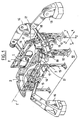
- the device according to the invention is intended for the assembly of vehicle bodies comprising a underbody 1 of the vehicle body, two sides of body 2 and a rear skirt 3.
- the device assembly includes a fixed frame 10 which has a mark X, Y, Z.
- this frame we can provide support for the underbody 1 of the motor vehicle body of so that the longitudinal axis 1 'of the base 1 is parallel to direction X.
- the means to bring this support and put it in position in the coordinate system are known in themselves and are not shown.
- This support can for example be constituted by a pallet which circulates by means of a conveyor passing through the frame 10 along the direction X, elevation means being provided in the frame to separate the pallet from the conveyor and the put in reference in the reference X, Y, Z.
- the assembly device includes a tool transverse intended to cooperate with the skirt 3 and two lateral tools intended to cooperate with the sides of box 2.
- the transverse tool is symbolized in the form of a frame 11 transverse to direction X and capable of being coupled to the frame 10 via, for example studs support 12.
- the studs 12 cooperate here with the frame 11 by four fixing points which ensure a complete immobilization of the frame 11 in the frame 10 both in translation along the X, Y, Z directions only in rotation around these.
- Frame 11 is here fitted on one of its faces, gripping and handling means for a robot 13 for its handling. On its other side, the frame 11 has clips to cooperate with the skirt 3.
- the side tools are symbolized in the form of frames 14 which are parallel to the Z direction and rest on the frame 10 by studs 15, which fixes their position in the direction Z.
- Each frame 14 is equipped on one of its sides of gripping and handling means for a robot 16 for its handling and on its other side of pliers to cooperate with the corresponding body side 2.
- each frame 14 is connected to frame 11 by means of a holding means position generally designated at 18 to maintain the frames 14 in a vertical braced position and braced by frame 11 and also fix the frames 14 in their position along the X direction.
- the frames 14 constitute the blocking elements in X and Z of the frame 11 which does not would cooperate directly with the frame 10 only by a stud immobilizing it in Y (for example by a Z axis pilot).
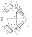
- the means for holding in position 18 are arranged to allow docking of the frame 11 by each of the frames 14 in a direction D1 parallel to the direction Y and a docking of the frames 14 by the frame 11 according to a direction D2 parallel to direction X (see Figures 2. and 3). These two docking directions are coplanar and form between them a docking angle ⁇ here equal to 90 °.
- the means for holding in position also allow a docking of tools in intermediate directions between the extreme directions D1 and D2.
- each means holding position 18 includes a male vee 19 and a vee female 20 having an opening angle ⁇ of approximately 120 °.
- the opening angle ⁇ of the ves is at least equal to the angle docking and preferably greater than this.
- the transverse tool is associated with two male vee 19 arranged symmetrically with respect to the axis 1 'to cooperate each with a lateral tool.
- Each male vee 19 is integral with the frame 11 so that it is centered on a direction parallel to the bisector of the docking angle, that is to say that in this case the bisector b of l opening angle ⁇ forms an angle of 45 ° with directions X and Y and extends in a plane parallel to the plane containing said directions X and Y.
- the female vee 20 are secured to one end of an arm 21 itself secured to the rear upright 17 of the frame 14 concerned to form an angle of 45 ° relative to the directions X and Y.
- the female vee 20 are mounted as the male ves 19 so as to be centered on a direction parallel to the bisector of the docking angle, that is to say that in this case the bisector b of the opening angle ⁇ of the female vee forms an angle of approximately 45 ° with the X and Y directions and is coplanar with them.
- An elongated opening 22 having a major axis 22 ′ contained in the plane of the directions of docking is arranged transversely in each female vee 20.
- Each means for holding in position 18 further comprises means for applying the male vee 19 against the female vee 20 along the bisector of the docking angle ⁇ and the bisector b of the opening angles ⁇ .
- This means comprises a pin 23 projecting from the male vee 19 along the bisector b symmetrically with respect thereto and parallel to the bisector of the docking angle.
- Two jaws 24 are mounted movable on the pin 23 to be actuated in a manner known per se by a control rod 25 (formed by the rod of a jack not shown) between an active position in which they extend laterally relative to the pin 23 ( Figure 5) and an inactive position in which they are retracted into the pin 23 ( Figure 4).
- cooperation between managers 11 and 14 and the corresponding body element 3, 2 can be done when we put frames 11 and 14 in the frame of station 10, the skirt 3, the base 1 and body sides 2 previously installed in the frame of the device then being pre-assembled.
- the pliers of frames 11 and 14 can also constitute means coupling the frame 11, 14 and the bodywork element 3, 2 correspondents implemented outside the line assembly, the frame 11, 14 then constituting a kind of body element transport pallet 3, 2 corresponding that the robot 13, 16 comes to set up in the device.
- each means 18 is introduced into the lumen 22 of the corresponding female vee 20 and moves along it until the male vee 19 is received in the female vee 20.
- the placing in the active position of the jaws 24 is controlled so that the latter pressing on the rear face 26 of the female vee 20 opposite the male vee 19 cause a tensile force on the male vee 19 which is applied against the vee female 20 in a direction parallel to the bisector b of the opening angle ⁇ of the ves (see FIG. 5) and then form a stop for the rear face 26.
- the opening angle ⁇ of the ves and the materials used to make these are determined to allow sliding of the faces of each vee in contact during the docking and application phases of the vee against each other.
- the normal to these faces and the direction of the force of application of the vee one against the other thus form an angle greater than the angle of friction of the materials used to make the vee.
- the rear parts of the body sides 2 and the skirt 3 are thus perfectly positioned by compared to the base 1 and this, very rigidly thanks to simple and light means.
- roof panels and cross members not shown between the body sides may be performed in the same station or in a next station. To do this, simply place the roof structure, i.e. the roof panel and sleepers between the stretchers (upper part) of body sides 2 by means of a frame like frame, to bring the sides of body towards each other so against the roof structure and to solder.
- each female vee 20 includes an inlet portion 20.1 having a opening angle ⁇ 1 equal to 120 ° and a bottom portion 20.2 having an opening angle ⁇ 2 equal to the docking angle ⁇ , or 90 °.
- Each male vee 19 has an opening angle ⁇ equal to the docking angle ⁇ and the opening angle ⁇ 2, i.e. 90 ° in this case.
- the inlet portion 20.1 of the female vee 20 exercises thus a dynamic guiding function of the male vee 19 during of the docking phase while the bottom portion 20.2 female vee 20 essentially performs a function of positioning of male vee 19 during positioning activates jaws 24.
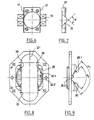
- the male vee 19 has two faces opposite transverse parallels 27 and that the female vee has two parallel transverse faces 28 extending facing each other from the light 22.
- the faces 27 and 28 are perpendicular to the Z direction of such so that when the male vee 19 is applied against the vee female 20, the faces 28 frame the faces 27 for immobilize the male vee and the female vee one relative to the other in direction Z. A relative positioning of tools in the direction Z is thus produced.
- the means for holding in position may include additional male and female ves to ensure relative positioning of the tools according to the Z direction, where male and female ves can include conical portions.
- opening angles of the ves can be used, determined in particular according to the value of the approach angle.
- transverse tool of the assembly device does not cooperate with an element bodywork and only performs the bracing function and bracing the side tools.
- the means for holding in position in accordance with the invention is not limited to the application described relating to the assembly device but can be used for holding all types of parts in position manipulated in particular by robots to be approached in two extreme directions of approach.
Landscapes
- Engineering & Computer Science (AREA)
- Manufacturing & Machinery (AREA)
- Chemical & Material Sciences (AREA)
- Combustion & Propulsion (AREA)
- Transportation (AREA)
- Mechanical Engineering (AREA)
- Automatic Assembly (AREA)
- Sampling And Sample Adjustment (AREA)
- Farming Of Fish And Shellfish (AREA)
- Vehicle Cleaning, Maintenance, Repair, Refitting, And Outriggers (AREA)
- Body Structure For Vehicles (AREA)
- Vehicle Body Suspensions (AREA)
- Medicines Containing Material From Animals Or Micro-Organisms (AREA)
Description
- la figure 1 est une vue schématique en perspective d'un dispositif d'assemblage de carrosseries de véhicules conforme à l'invention,
- la figure 2 est une vue partielle de dessus illustrant un premier mode d'approche mutuelle des outils du dispositif conforme à l'invention,
- la figure 3 est une vue analogue à la figure 2 montrant un deuxième mode d'approche mutuelle des outils,
- la figure 4 est une vue en perspective d'un moyen de maintien en position de deux outils en cours d'approche,
- la figure 5 est une vue partielle en coupe de deux outils maintenus en position l'un par rapport à l'autre,
- les figures 6 et 7 sont des vues de face et de côté d'une variante de réalisation du vé mâle du dispositif de l'invention,
- les figures 8 et 9 sont des vues analogues aux figures 6 et 7 de la variante de réalisation correspondante du vé femelle.
Claims (9)
- Moyen de maintien en position de deux pièces destinées à être approchées l'une de l'autre selon au moins deux directions extrêmes d'accostage (D1, D2) coplanaires formant entre elles un angle d'accostage (β), caractérisé en ce que le moyen de maintien en position comprend d'une part au moins un vé mâle (19) et un vé femelle (20) pourvus chacun de moyens de sa fixation à une des pièces de telle manière que chaque vé soit centré sensiblement sur une direction parallèle à la bissectrice de l'angle d'accostage et le vé femelle possédant une portion d'entrée (20.1) ayant un angle d'ouverture (α1, α) au moins égal à l'angle d'accostage, et d'autre part, un moyen (23, 24) pour appliquer le vé mâle contre le vé femelle selon ladite bissectrice.
- Moyen de maintien en position selon la revendication 1, caractérisé en ce que les vés (19, 20) ont des angles d'ouverture (α) sensiblement égaux qui sont supérieurs à l'angle d'accostage (β).
- Moyen de maintien en position selon la revendication 2, caractérisé en ce que, pour un angle d'accostage (β) d'environ 90°, les angles d'ouverture (α) des vés (19, 20) sont égaux à environ 120°.
- Moyen de maintien en position selon la revendication 1, caractérisé en ce que le vé femelle (20) possède une portion de fond (20.2) ayant un angle d'ouverture (α2) sensiblement égal à l'angle d'ouverture du vé mâle (19) qui est au moins égal à l'angle d'accostage (β), et en ce que l'angle d'ouverture (α1) de la portion d'entrée (20.1) du vé femelle est supérieur à l'angle d'ouverture (α2) de la portion de fond (20.2) de celui-ci.
- Moyen de maintien en position selon la revendication 4, caractérisé en ce que, pour un angle d'accostage (β) sensiblement égal à 90°, l'angle d'ouverture (α2) du vé mâle et de la portion de fond (20.2) du vé femelle (20) est sensiblement égal à 90° et l'angle d'ouverture (α1) de la portion d'entrée (20.1) du ve femelle (20) est sensiblement égal à 120°.
- Moyen de maintien en position selon l'une quelconque des revendications 1 à 5, caractérisé en ce que le moyen pour appliquer comprend un pion (23) s'étendant en saillie du vé mâle (19) symétriquement par rapport à celui-ci pour être introduit dans une lumière allongée (22) ménagée dans le vé femelle (20) et de grand axe contenu dans le plan des directions d'accostage, au moins une mâchoire (24) étant montée mobile sur le pion (23) pour être actionnée entre une position active dans laquelle elle forme une butée pour une face arrière (26) du vé femelle opposée au vé mâle et une position inactive dans laquelle elle est escamotée et permet le passage libre du pion dans la lumière du vé femelle.
- Dispositif d'assemblage d'une carrosserie, comportant deux outils latéraux (14) de support de côtés de caisse (2) et un outil transversal (11) à ces deux outils latéraux, caractérisé en ce que le dispositif comprend des moyens (18) conformes à l'une quelconque des revendications précédentes pour maintenir en position les uns par rapport aux autres les outils latéraux et l'outil transversal, l'outil transversal comportant au moins deux vés (19) disposés symétriquement par rapport à un axe longitudinal de la carrosserie et destinés à coopérer avec des vés (20) correspondants fixés sur les outils latéraux.
- Dispositif selon la revendication 7 prise en dépendance de la revendication 3 ou 5, caractérisé en ce que la bissectrice (b) des angles d'ouverture (α) des vés (19, 20) forme avec l'axe longitudinal de la carrosserie un angle d'environ 45°.
- Dispositif selon la revendication 7 ou la revendication 8, caractérisé en ce que les vés solidaires de l'outil transversal (11) sont des vés mâles (19) et les vés solidaires des outils latéraux (14) sont des vés femelles (20) .
Applications Claiming Priority (3)
| Application Number | Priority Date | Filing Date | Title |
|---|---|---|---|
| FR9912620 | 1999-10-11 | ||
| FR9912620A FR2799428B1 (fr) | 1999-10-11 | 1999-10-11 | Moyen de maintien en position de deux pieces l'une par rapport a l'autre |
| PCT/FR2000/002765 WO2001026953A1 (fr) | 1999-10-11 | 2000-10-05 | Moyen de maintien en position de deux pieces l'une par rapport a l'autre. |
Publications (2)
| Publication Number | Publication Date |
|---|---|
| EP1220774A1 EP1220774A1 (fr) | 2002-07-10 |
| EP1220774B1 true EP1220774B1 (fr) | 2004-01-28 |
Family
ID=9550758
Family Applications (1)
| Application Number | Title | Priority Date | Filing Date |
|---|---|---|---|
| EP00967951A Expired - Lifetime EP1220774B1 (fr) | 1999-10-11 | 2000-10-05 | Moyen de maintien en position de deux pieces l'une par rapport a l'autre. |
Country Status (8)
| Country | Link |
|---|---|
| US (1) | US6851166B1 (fr) |
| EP (1) | EP1220774B1 (fr) |
| AT (1) | ATE258519T1 (fr) |
| DE (1) | DE60008008T2 (fr) |
| ES (1) | ES2213612T3 (fr) |
| FR (1) | FR2799428B1 (fr) |
| PT (1) | PT1220774E (fr) |
| WO (1) | WO2001026953A1 (fr) |
Families Citing this family (8)
| Publication number | Priority date | Publication date | Assignee | Title |
|---|---|---|---|---|
| DE10258633A1 (de) * | 2002-12-16 | 2004-07-08 | Kuka Roboter Gmbh | Verfahren und Vorrichtung zum Positionieren von zusammenzufügenden Bauteilen |
| US7100271B2 (en) | 2003-09-23 | 2006-09-05 | Valiant Corporation | Automotive vehicle framing system |
| US7685699B2 (en) | 2003-09-23 | 2010-03-30 | Variant Corporation | Docking apparatus |
| ITTO20060917A1 (it) * | 2006-12-22 | 2008-06-23 | Comau Spa | Sistema per l assemblaggio, in particolare mediante saldatura, di strutture costituite da elementi di lamiera stampata, come scocche di autoveicoli o loro sottogruppi |
| DE202007004183U1 (de) * | 2007-03-16 | 2008-08-07 | Kuka Systems Gmbh | Rahmungseinrichtung |
| US8046895B2 (en) * | 2008-01-21 | 2011-11-01 | Ford Motor Company | System and method for assembling a vehicle body structure |
| US8239063B2 (en) * | 2008-07-29 | 2012-08-07 | Fanuc Robotics America, Inc. | Servo motor monitoring and hood/deck exchange to enhance the interior coating process |
| US10882150B2 (en) * | 2018-08-24 | 2021-01-05 | ARRTSM GmbH | Autonomous processing station |
Family Cites Families (8)
| Publication number | Priority date | Publication date | Assignee | Title |
|---|---|---|---|---|
| DE2341708A1 (de) * | 1972-08-31 | 1974-03-14 | Industrial Acoustics Co | Sicherheitsschraube |
| DE3545449A1 (de) * | 1985-12-20 | 1987-06-25 | Bayerische Motoren Werke Ag | Vorrichtung und verfahren zum zusammenfuegen von aggregaten von der unterseite her an einer kraftfahrzeugkarosse |
| IT1223690B (it) * | 1988-07-13 | 1990-09-29 | Comau Spa | Dispositivo per la saldatura di scocche di autoveicoli |
| IT1288733B1 (it) * | 1996-10-08 | 1998-09-24 | Comau Spa | Dispositivo per la saldatura a punti di strutture costituite da elementi metallici, in particolare scocche di autoveicoli o loro |
| EP0927598A1 (fr) * | 1997-12-18 | 1999-07-07 | COMAU S.p.A. | Dispositif de soudage par points de carosseries de véhicules à moteur ou sous-ensemble de celui-ci |
| FR2779405B1 (fr) * | 1998-06-09 | 2000-07-13 | Abb Preciflex Systems | Procede de realisation d'une carrosserie automobile |
| FR2791916B1 (fr) * | 1999-04-06 | 2001-05-04 | Abb Preciflex Systems | Procede de maintien en position d'une piece dans un poste d'assemblage |
| IT1313897B1 (it) * | 1999-10-25 | 2002-09-26 | Fata Group S P A | Stazione automatica migliorata di assemblaggio e saldatura di scocchedi autoveicoli |
-
1999
- 1999-10-11 FR FR9912620A patent/FR2799428B1/fr not_active Expired - Fee Related
-
2000
- 2000-10-05 EP EP00967951A patent/EP1220774B1/fr not_active Expired - Lifetime
- 2000-10-05 PT PT00967951T patent/PT1220774E/pt unknown
- 2000-10-05 US US10/089,731 patent/US6851166B1/en not_active Expired - Lifetime
- 2000-10-05 ES ES00967951T patent/ES2213612T3/es not_active Expired - Lifetime
- 2000-10-05 WO PCT/FR2000/002765 patent/WO2001026953A1/fr not_active Ceased
- 2000-10-05 AT AT00967951T patent/ATE258519T1/de active
- 2000-10-05 DE DE60008008T patent/DE60008008T2/de not_active Expired - Lifetime
Also Published As
| Publication number | Publication date |
|---|---|
| WO2001026953A1 (fr) | 2001-04-19 |
| ATE258519T1 (de) | 2004-02-15 |
| ES2213612T3 (es) | 2004-09-01 |
| EP1220774A1 (fr) | 2002-07-10 |
| DE60008008T2 (de) | 2004-10-21 |
| DE60008008D1 (de) | 2004-03-04 |
| PT1220774E (pt) | 2004-06-30 |
| US6851166B1 (en) | 2005-02-08 |
| FR2799428A1 (fr) | 2001-04-13 |
| FR2799428B1 (fr) | 2001-12-21 |
Similar Documents
| Publication | Publication Date | Title |
|---|---|---|
| EP1084055B1 (fr) | Procede de realisation d'une carrosserie automobile | |
| EP0726860B1 (fr) | Procede et dispositif d'assemblage pour pieces de carrosserie | |
| FR2608546A1 (fr) | Mecanisme d'accouplement d'organes d'articulation de porte sur une coque d'automobile | |
| FR2532576A1 (fr) | Dispositif automatique pour l'assemblage et le soudage de carrosseries de vehicules automobiles | |
| WO1996035547A1 (fr) | Dispositif d'indexation d'une piece a travers un trou de cette piece | |
| EP1220774A1 (fr) | Moyen de maintien en position de deux pieces l'une par rapport a l'autre. | |
| EP2586648A1 (fr) | Système comprenant une glissière de siège de véhicule automobile et un support destiné a y etre fixé et procédé de fabrication d'un tel système | |
| EP1131241B1 (fr) | Dispositif de montage et de mise en geometrie d'une aile sur la structure d'un vehicule automobile | |
| EP2279109A1 (fr) | Agencement pour la mise en position d'un pavillon sur une caisse | |
| FR2563293A1 (fr) | Piece de jonction pour assembler avec serrage deux profiles, notamment equerre pour assemblage d'onglet et embout pour assemblage en bout | |
| FR2651699A1 (fr) | Installation de pliage des rebords d'une portiere de vehicule automobile. | |
| EP0419383A1 (fr) | Dispositif de fixation d'un véhicule et de réglage de sa position sur un châssis en vue de sa réparation | |
| EP2812230B1 (fr) | Structure de montage d'un poste de conduite d'un vehicule | |
| EP1467835B1 (fr) | Structure pour le maintien d'une pièce de carrosserie | |
| EP0581687A1 (fr) | Dispositif de transport de pièces volumineuses | |
| EP2132055B1 (fr) | Procédé de montage d'un élément de soubassement transversal et d'une face avant technique sur un véhicule automobile | |
| EP3945003B1 (fr) | Dispositif de bridage d'un garde-corps amovible sécurisé sur un marchepied d'un wagon d'un véhicule de transport ferroviaire et garde-corps équipé d'un tel dispositif de bridage | |
| WO2006082349A1 (fr) | Procede d'assemblage d'un pavillon de vehicule automobile et moyens associes | |
| EP0581627B1 (fr) | Procédé de fixation d'un essieu de véhicule sur le soubassement de la caisse de ce véhicule | |
| EP0765699A1 (fr) | Châssis de redressage pour carrosserie automobile | |
| FR2650209A1 (fr) | Cellule de presse a sertir | |
| EP1018448A1 (fr) | Dispositif de suspension d'un groupe motopropulseur dans la caisse d'un vehicule automobile | |
| EP1754651A2 (fr) | Assemblage de profiles creux à section fermée | |
| WO2025016813A1 (fr) | Méthode d'assemblage de véhicules automobiles électriques et installation de mise en oeuvre | |
| EP0549453A1 (fr) | Dispositif formant interface mécanique interposée entre l'extrémité d'un robot et un outil de travail du robot |
Legal Events
| Date | Code | Title | Description |
|---|---|---|---|
| PUAI | Public reference made under article 153(3) epc to a published international application that has entered the european phase |
Free format text: ORIGINAL CODE: 0009012 |
|
| 17P | Request for examination filed |
Effective date: 20020403 |
|
| AK | Designated contracting states |
Kind code of ref document: A1 Designated state(s): AT BE CH CY DE DK ES FI FR GB GR IE IT LI LU MC NL PT SE |
|
| 17Q | First examination report despatched |
Effective date: 20020902 |
|
| GRAH | Despatch of communication of intention to grant a patent |
Free format text: ORIGINAL CODE: EPIDOS IGRA |
|
| GRAS | Grant fee paid |
Free format text: ORIGINAL CODE: EPIDOSNIGR3 |
|
| GRAA | (expected) grant |
Free format text: ORIGINAL CODE: 0009210 |
|
| AK | Designated contracting states |
Kind code of ref document: B1 Designated state(s): AT BE CH CY DE DK ES FI FR GB GR IE IT LI LU MC NL PT SE |
|
| PG25 | Lapsed in a contracting state [announced via postgrant information from national office to epo] |
Ref country code: CY Free format text: LAPSE BECAUSE OF FAILURE TO SUBMIT A TRANSLATION OF THE DESCRIPTION OR TO PAY THE FEE WITHIN THE PRESCRIBED TIME-LIMIT Effective date: 20040128 Ref country code: IE Free format text: LAPSE BECAUSE OF FAILURE TO SUBMIT A TRANSLATION OF THE DESCRIPTION OR TO PAY THE FEE WITHIN THE PRESCRIBED TIME-LIMIT Effective date: 20040128 Ref country code: FI Free format text: LAPSE BECAUSE OF FAILURE TO SUBMIT A TRANSLATION OF THE DESCRIPTION OR TO PAY THE FEE WITHIN THE PRESCRIBED TIME-LIMIT Effective date: 20040128 |
|
| REG | Reference to a national code |
Ref country code: GB Ref legal event code: FG4D Free format text: NOT ENGLISH |
|
| REG | Reference to a national code |
Ref country code: CH Ref legal event code: EP |
|
| REG | Reference to a national code |
Ref country code: IE Ref legal event code: FG4D Free format text: FRENCH |
|
| REF | Corresponds to: |
Ref document number: 60008008 Country of ref document: DE Date of ref document: 20040304 Kind code of ref document: P |
|
| GBT | Gb: translation of ep patent filed (gb section 77(6)(a)/1977) |
Effective date: 20040318 |
|
| PG25 | Lapsed in a contracting state [announced via postgrant information from national office to epo] |
Ref country code: DK Free format text: LAPSE BECAUSE OF FAILURE TO SUBMIT A TRANSLATION OF THE DESCRIPTION OR TO PAY THE FEE WITHIN THE PRESCRIBED TIME-LIMIT Effective date: 20040428 Ref country code: GR Free format text: LAPSE BECAUSE OF FAILURE TO SUBMIT A TRANSLATION OF THE DESCRIPTION OR TO PAY THE FEE WITHIN THE PRESCRIBED TIME-LIMIT Effective date: 20040428 |
|
| REG | Reference to a national code |
Ref country code: SE Ref legal event code: TRGR |
|
| REG | Reference to a national code |
Ref country code: PT Ref legal event code: SC4A Free format text: AVAILABILITY OF NATIONAL TRANSLATION Effective date: 20040426 |
|
| REG | Reference to a national code |
Ref country code: IE Ref legal event code: FD4D |
|
| REG | Reference to a national code |
Ref country code: ES Ref legal event code: FG2A Ref document number: 2213612 Country of ref document: ES Kind code of ref document: T3 |
|
| PG25 | Lapsed in a contracting state [announced via postgrant information from national office to epo] |
Ref country code: LU Free format text: LAPSE BECAUSE OF NON-PAYMENT OF DUE FEES Effective date: 20041005 |
|
| PG25 | Lapsed in a contracting state [announced via postgrant information from national office to epo] |
Ref country code: LI Free format text: LAPSE BECAUSE OF NON-PAYMENT OF DUE FEES Effective date: 20041031 Ref country code: CH Free format text: LAPSE BECAUSE OF NON-PAYMENT OF DUE FEES Effective date: 20041031 Ref country code: MC Free format text: LAPSE BECAUSE OF NON-PAYMENT OF DUE FEES Effective date: 20041031 |
|
| PLBE | No opposition filed within time limit |
Free format text: ORIGINAL CODE: 0009261 |
|
| STAA | Information on the status of an ep patent application or granted ep patent |
Free format text: STATUS: NO OPPOSITION FILED WITHIN TIME LIMIT |
|
| 26N | No opposition filed |
Effective date: 20041029 |
|
| REG | Reference to a national code |
Ref country code: CH Ref legal event code: PL |
|
| PGFP | Annual fee paid to national office [announced via postgrant information from national office to epo] |
Ref country code: PT Payment date: 20061003 Year of fee payment: 7 |
|
| REG | Reference to a national code |
Ref country code: PT Ref legal event code: MM4A Free format text: LAPSE DUE TO NON-PAYMENT OF FEES Effective date: 20080407 |
|
| PG25 | Lapsed in a contracting state [announced via postgrant information from national office to epo] |
Ref country code: PT Free format text: LAPSE BECAUSE OF NON-PAYMENT OF DUE FEES Effective date: 20080407 |
|
| REG | Reference to a national code |
Ref country code: DE Ref legal event code: R082 Ref document number: 60008008 Country of ref document: DE Representative=s name: SCHAUMBURG & PARTNER PATENTANWAELTE GBR, DE Ref country code: DE Ref legal event code: R082 Ref document number: 60008008 Country of ref document: DE Representative=s name: SCHAUMBURG & PARTNER PATENTANWAELTE MBB, DE Ref country code: DE Ref legal event code: R082 Ref document number: 60008008 Country of ref document: DE Representative=s name: SCHAUMBURG UND PARTNER PATENTANWAELTE MBB, DE |
|
| REG | Reference to a national code |
Ref country code: FR Ref legal event code: PLFP Year of fee payment: 16 |
|
| REG | Reference to a national code |
Ref country code: FR Ref legal event code: PLFP Year of fee payment: 17 |
|
| REG | Reference to a national code |
Ref country code: FR Ref legal event code: PLFP Year of fee payment: 18 |
|
| REG | Reference to a national code |
Ref country code: FR Ref legal event code: PLFP Year of fee payment: 19 |
|
| PGFP | Annual fee paid to national office [announced via postgrant information from national office to epo] |
Ref country code: NL Payment date: 20191021 Year of fee payment: 20 Ref country code: SE Payment date: 20191021 Year of fee payment: 20 Ref country code: DE Payment date: 20191021 Year of fee payment: 20 |
|
| PGFP | Annual fee paid to national office [announced via postgrant information from national office to epo] |
Ref country code: ES Payment date: 20191122 Year of fee payment: 20 Ref country code: FR Payment date: 20191028 Year of fee payment: 20 Ref country code: IT Payment date: 20191028 Year of fee payment: 20 Ref country code: BE Payment date: 20191021 Year of fee payment: 20 |
|
| PGFP | Annual fee paid to national office [announced via postgrant information from national office to epo] |
Ref country code: AT Payment date: 20191022 Year of fee payment: 20 |
|
| PGFP | Annual fee paid to national office [announced via postgrant information from national office to epo] |
Ref country code: GB Payment date: 20191021 Year of fee payment: 20 |
|
| REG | Reference to a national code |
Ref country code: DE Ref legal event code: R071 Ref document number: 60008008 Country of ref document: DE |
|
| REG | Reference to a national code |
Ref country code: NL Ref legal event code: MK Effective date: 20201004 |
|
| REG | Reference to a national code |
Ref country code: GB Ref legal event code: PE20 Expiry date: 20201004 Ref country code: BE Ref legal event code: MK Effective date: 20201005 |
|
| REG | Reference to a national code |
Ref country code: AT Ref legal event code: MK07 Ref document number: 258519 Country of ref document: AT Kind code of ref document: T Effective date: 20201005 |
|
| PG25 | Lapsed in a contracting state [announced via postgrant information from national office to epo] |
Ref country code: GB Free format text: LAPSE BECAUSE OF EXPIRATION OF PROTECTION Effective date: 20201004 |
|
| REG | Reference to a national code |
Ref country code: ES Ref legal event code: FD2A Effective date: 20220103 |
|
| PG25 | Lapsed in a contracting state [announced via postgrant information from national office to epo] |
Ref country code: ES Free format text: LAPSE BECAUSE OF EXPIRATION OF PROTECTION Effective date: 20201006 |