EP1220593A2 - Electric connection box - Google Patents
Electric connection box Download PDFInfo
- Publication number
- EP1220593A2 EP1220593A2 EP01130480A EP01130480A EP1220593A2 EP 1220593 A2 EP1220593 A2 EP 1220593A2 EP 01130480 A EP01130480 A EP 01130480A EP 01130480 A EP01130480 A EP 01130480A EP 1220593 A2 EP1220593 A2 EP 1220593A2
- Authority
- EP
- European Patent Office
- Prior art keywords
- relay
- fuse
- unit
- electric connection
- connection box
- Prior art date
- Legal status (The legal status is an assumption and is not a legal conclusion. Google has not performed a legal analysis and makes no representation as to the accuracy of the status listed.)
- Withdrawn
Links
Images




Classifications
-
- H—ELECTRICITY
- H05—ELECTRIC TECHNIQUES NOT OTHERWISE PROVIDED FOR
- H05K—PRINTED CIRCUITS; CASINGS OR CONSTRUCTIONAL DETAILS OF ELECTRIC APPARATUS; MANUFACTURE OF ASSEMBLAGES OF ELECTRICAL COMPONENTS
- H05K7/00—Constructional details common to different types of electric apparatus
- H05K7/02—Arrangements of circuit components or wiring on supporting structure
- H05K7/026—Multiple connections subassemblies
-
- H—ELECTRICITY
- H01—ELECTRIC ELEMENTS
- H01H—ELECTRIC SWITCHES; RELAYS; SELECTORS; EMERGENCY PROTECTIVE DEVICES
- H01H11/00—Apparatus or processes specially adapted for the manufacture of electric switches
- H01H2011/0093—Standardization, e.g. limiting the factory stock by limiting the number of unique, i.e. different components
-
- H—ELECTRICITY
- H01—ELECTRIC ELEMENTS
- H01H—ELECTRIC SWITCHES; RELAYS; SELECTORS; EMERGENCY PROTECTIVE DEVICES
- H01H85/00—Protective devices in which the current flows through a part of fusible material and this current is interrupted by displacement of the fusible material when this current becomes excessive
- H01H85/02—Details
- H01H85/20—Bases for supporting the fuse; Separate parts thereof
- H01H2085/2075—Junction box, having holders integrated with several other holders in a particular wiring layout
- H01H2085/208—Junction box, having holders integrated with several other holders in a particular wiring layout specially adapted for vehicles
-
- H—ELECTRICITY
- H01—ELECTRIC ELEMENTS
- H01H—ELECTRIC SWITCHES; RELAYS; SELECTORS; EMERGENCY PROTECTIVE DEVICES
- H01H85/00—Protective devices in which the current flows through a part of fusible material and this current is interrupted by displacement of the fusible material when this current becomes excessive
- H01H85/02—Details
- H01H85/20—Bases for supporting the fuse; Separate parts thereof
- H01H85/2045—Mounting means or insulating parts of the base, e.g. covers, casings
-
- H—ELECTRICITY
- H01—ELECTRIC ELEMENTS
- H01H—ELECTRIC SWITCHES; RELAYS; SELECTORS; EMERGENCY PROTECTIVE DEVICES
- H01H9/00—Details of switching devices, not covered by groups H01H1/00 - H01H7/00
- H01H9/10—Adaptation for built-in fuses
Definitions
- This invention relates to an electric connection box mounted on a vehicle such as an automobile.
- Fig. 8 shows an electric connection box (In this specification, a relay box is shown as an example) to be mounted on a vehicle such as an automobile.
- the illustrated electric connection box 1 has a plurality of fuse cavities 3, relay cavities 4 and so on provided at a box body 2. Terminals (not shown), each press-connected to an end of a wire, are inserted in the fuse cavities 3 and relay cavities 4, respectively, and these fuse cavities and relay cavities are connected respectively to corresponding fuses and relays (not shown) through the terminals and wires.
- a power circuit is constituted.
- the power circuits to be used in vehicles are different in specification from one another, or the power circuits to be used even in the same kind of vehicle are different in specification from one another according to the grade. Therefore, it is necessary to provide new electric connection boxes each designed for the corresponding vehicle or for the corresponding grade. Namely, the related electric connection box did not have a general-purpose design, and this greatly affected the production cost.
- This invention has been made under the above circumstances, and an object of the invention is to provide an electric connection box which has a general-purpose design, and contributes to the reduction of a cost.
- the invention is characterized by having the following arrangement.
- one common power circuit relay unit is formed.
- This relay unit is formed by the fuse and one or more relays associated with the fuse, the fuse and the relays being common to vehicles or grades.
- One or more kinds of the relay units are provided, and are releasably attached to the cover member.
- the relay unit itself has the function of a relay box.
- the attaching portion and the option attaching portion are formed at the cover member.
- the relay unit is attached to this attaching portion.
- the cover member having the plurality of option attaching portions arranged in a juxtaposed manner.
- the relation between the width of the option attaching portion and the width of the attaching portion becomes clear.
- the width of the relay units is standardized.
- the relay single unit comprising the single relay, is further releasably attached to the cover member.
- the relay unit having the relay and the fuse combined together in a packaged manner, is releasably attached to the box body.
- Fig. 1 is an exploded, perspective view of one preferred embodiment of an electric connection box of the invention.
- Figs . 2A to 2D are power circuit diagrams of relay units, respectively.
- the electric connection box 21 to be mounted on a vehicle such as an automobile comprises a plurality of relay units 22 and 23, an optional unit (not shown), and a cover member 24 of a synthetic resin for these parts.
- the relay unit 22 comprises a unit casing 25 made of a synthetic resin, a fuse 26 of a known construction, and a relay 27 of a known construction.
- the unit casing 25 is formed into a rectangular box-like shape with an open bottom.
- a fuse cavity 28, into which the fuse 26 is inserted, and a relay cavity 29, into which the relay 27 is inserted, are formed integrally on an upper wall of the unit casing 25.
- Rails 30 and 30 are formed respectively on a pair of right and left walls of the unit casing 25 extending in an attaching direction P (described later).
- a pair of front and rear walls, disposed perpendicularly to the pair of right and left walls, are flat.
- Connection terminals (not shown) for connection to terminals (not shown) of the fuse 26 are inserted into the fuse cavity 28. These connection terminals are inserted into the fuse cavity 28 through the open bottom of the unit casing 25. Ends of wires 31 are press-connected to these connection terminals, respectively.
- Connection terminals (not shown) for connection to terminals (not shown) of the relay 27 are inserted in the relay cavity 29. Like the connection terminals for the fuse cavity 28, these connection terminals are inserted into the relay cavity 29 through the open bottom of the unit casing 25. Ends of wires 31 are press-connected to these connection terminals, respectively.
- the rails 30 and 30 are parallel to the attaching direction P (described later) .
- an elongate projection formed between these grooves, defines the rail 30.
- a retaining projection is formed on each of the rails 30 and 30 (This is not limited to such a projection).
- the relay unit 23 comprises a unit casing 32 made of a synthetic resin, a fuse 33 of a known construction, and relays 34 and 34 of a known construction.
- the unit casing 32 is formed into a rectangular box-like shape with an open bottom.
- a fuse cavity 35, into which the fuse 33 is inserted, and relay cavities 36 and 36, into which the relays 34 and 34 are inserted, respectively, are formed integrally on an upper wall of the unit casing 32.
- Rails 37 and 37 are formed respectively on a pair of right and left walls of the unit casing 37 extending in the attaching direction P (described later) .
- a pair of front and rear walls, disposed perpendicularly to the pair of right and left walls, are flat.
- these right and left walls of the unit casing 37 are twice larger in length than the right and left walls of the unit casing 25.
- the length (that is, the width) of the front and rear walls of the unit casing 37 is the same as the length (that is, the width) of the front and rear walls of the casing unit 25.
- Connection terminals (not shown) for connection to terminals (not shown) of the fuse 33 are inserted into the fuse cavity 35. These connection terminals are inserted into the fuse cavity 35 through the open bottom of the unit casing 32. Ends of wires 31 are press-connected to these connection terminals, respectively.
- Connection terminals (not shown) for connection to terminals (not shown) of the corresponding relay 34 are inserted in each of the relay cavities 36 and 36. Like the connection terminals for the fuse cavity 35, these connection terminals are inserted into the relay cavity 36 through the open bottom of the unit casing 32. Ends of wires 31 are press-connected to these connection terminals, respectively.
- the rails 37 and 37 are parallel to the attaching direction P (described later) .
- an elongate projection formed between these grooves, defines the rail 37.
- a retaining projection is formed on each of the rails 37 and 37 (This is not limited to such a projection).
- the fuses 26 and 33 and the relays 27 and 34 are of a known construction, and description of details thereof will be omitted.
- the above-mentioned optional unit is an optional power circuit, required in accordance with a specification requirement of a vehicle, and is similar in construction to the relay unit 22 or 23 (It comprises a unit casing, a fuse and a relay, or a unit casing and a relay, or a unit casing and a fuse, or the like).
- the relay units 22 and 23 will be described in detail.
- the relay unit 22 is constructed, for example, as shown in Fig. 2A or 2B, and the relay unit 23 is constructed, for example, as shown in Fig. 2C or 2D.
- one common power circuit relay unit 22 is constituted by the fuse 26 and the relay 27 associated with this fuse 26.
- One common power circuit relay unit 23 is constituted by the fuse 33 and the relays 34 and 34 associated with this fuse 33.
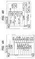
- fuses and relays which are common to a vehicle A and a vehicle B as shown in Figs. 3 and 4, are selected, and are provided as units, and these are designed to form the above power circuit (Those fuses and relays, which are common to grades, may be taken out to be provided as units).
- Each of the relay units 22 and 23 itself has the function of a relay box.
- the cover member 24 includes the attaching portion 38 and an option attaching portion 39, and the relay units 22 and 23 are attached to the attaching portion 38, and the optional unit is attached to the option attaching portion 39.
- the attaching portion 38 is a portion formed by a side wall 41, an inner end wall 42 and a partition wall 43 which are provided perpendicularly to a base plate 40 of the cover member 24.
- the relay units 22 and 23 can be slidably attached to this attaching portion. More specifically, rail sliding grooves 44 and 44 are formed respectively in opposed surfaces of the side wall 41 and the partition wall 43, and the rails 30 and 30 of the relay unit 22, as well as the rails 37 and 37 of the relay unit 23, can slide along these rail sliding grooves.
- each of the side wall 41 and the partition wall 43 When a pair of elongate projections are formed on each of the side wall 41 and the partition wall 43, that portion of each of these walls, lying between these elongate projections, defines the rail sliding groove 44.
- a recess in which the retaining projection is engageable, is formed in each of the rail slide groove portions 44 and 44 (This is not limited to such a recess) .
- the option attaching portion 39 is a portion formed by a side wall 45, the inner end wall 42 and the partition wall 43 which are provided perpendicularly to the base plate 40 of the cover member 24 .
- the optional unit can be slidably attached to this option attaching portion. More specifically, rail sliding grooves 46 and 46 are formed respectively in opposed surfaces of the side wall 45 and the partition wall 43, and rails of the optional unit can slide along these rail sliding grooves.
- the rail sliding grooves 46 and 46 are formed in the same manner as described above for the rail sliding grooves 44 and 44 of the attaching portion 38.
- a plurality of option attaching portions 39 can be formed in a juxtaposed manner at the cover member 24 if necessary. This is advantageous from the viewpoint of the cost when many optional units need to be attached.
- the width L2 of the option attaching portion 39 is equal to or an integral multiple of the width L1 of the attaching portion 38. With this construction, the relation between the width L2 of the option attaching portion 39 and the width L1 of the attaching portion 38 becomes clear, so that the general-purpose ability can be enhanced. In other words, the width of the relay unit 22 and so on is standardized, so that the general-purpose ability is enhanced (The width L1 of the attaching portion 38 may be determined after the width of the relay unit 22 and so on is standardized).
- the relay units 22 and 23 are attached to the attaching portion 38 of the cover member 24, and the optional unit is attached to the option attaching portion 39 of the cover member 24, thereby assembling the electric connection box 21 of the invention.
- the relay units 22 and 23, as well as the optional unit are slid in the attaching direction (indicated by arrow P), and are releasably attached.
- the relay units 22 and 23 are not always attached in a consecutive manner. For example, three relay units 22 may be attached.
- a relay single unit 47, shown in Fig. 5, and a fuse single unit 48, shown in Fig. 6, may be attached (The relay single unit 47 comprises a unit casing 49, including a relay cavity 29 and rails 30 and 30, and a relay 27.
- the fuse single unit 48 comprises a unit casing 50, including fuse cavities 28 and 28 and rails 30 and 30, and fuses 26 and 26.).
- the optional unit may not be attached.
- the relay 27 (relays 34) and the fuse 26 (33) are combined together to provide a unit, and these units are releasably attached to the cover member 24.
- the electric connection box 21 can have a general-purpose design. The cost can be reduced because of the general-purpose design of the electric connection box 21.
- the packaging of a system, provided on the vehicle can be achieved.
- Fig. 7 is an exploded, perspective view of another embodiment of an electric connectionbox of the present invention.
- the electric connection box 61 shown in Fig. 7, comprises one or more relay units 62, and a box body 63 to which the relay unit(s) 62 is releasably attached.
- the relay unit 62 comprises a relay body 64, and a fusible member 65.
- a relay and a fuse are combined together in a packaged manner.
- the relay unit 62 includes the fusible member 65 contained in the relay body 64 defined by a base plate 66 (of the relay body 64) and an outer cover 67.
- the electric connection box 61 can have a general-purpose design since it is provided with the relay unit 62 in which the relay and the fuse are combined together in a packaged manner. And besides, the cost can be reduced because of the general-purpose design of the electric connection box 61. Furthermore, with the above construction, the packaging of a system, providedon the vehicle, can be achieved.
- the relay and the fuse are combined together as a unit, and this unit is releasably attached to the cover member.
- the electric connection box can have a general-purpose design. And besides, the cost of the electric connection box can be reduced because of its general-purpose design. Furthermore, the packaging of the system, provided on the vehicle, can be achieved.
- the optional power circuit part (optional unit), required in accordance with a specification requirement, can be attached to the cover member. Therefore, the general-purpose ability is enhanced, so that the cost can be further reduced.
- the cover member having the plurality of option attaching portions arranged in a juxtaposed manner, is newly provided if necessary, and this contributes to the reduction of the cost of the electric connection box.
- the relation between the width of the option attaching portion and the width of the attaching portion is made clear, so that the general-purpose ability is enhanced.
- the width of the relay units is standardized, so that the general-purpose ability is enhanced.
- the relay single unit comprising the single relay, is further releasably attached to the cover member, so that the general-purpose ability is enhanced.
- the relay unit having the relay and the fuse combined together in a packaged manner, and therefore the electric connection box can have the general-purpose design. And besides, the cost of the electric connection box can be reduced because of its general-purpose design. Furthermore, the packaging of the system, provided on the vehicle, can be achieved.
Landscapes
- Engineering & Computer Science (AREA)
- Microelectronics & Electronic Packaging (AREA)
- Connection Or Junction Boxes (AREA)
- Fuses (AREA)
Abstract
Description
Claims (6)
- An electric connection box comprising:a common power circuit relay unit for formed by a fuse and at least one relay associated with fuse, the fuse and the at least one relay being common to vehicles or grades,a cover member to which one or more kinds of the relay unit are releasably attached.
- The electric connection box according to claim 1, wherein an option attaching portion for an optional power circuit required in accordance with a specification requirement is formed, separately from an attaching portion for the relay units, at the cover member.
- The electric connection box according to claim 2, wherein the cover member is so formed that a plurality of the option attaching portions can be arranged in a juxtaposed manner.
- The electric connection box according to claim 2, wherein a width of the option attaching portion is equal to or an integral multiple of a width of the attaching portion for the relay units .
- An electric connection box according to claim 1, wherein a relay single unit including a single relay is releasably attached to the cover member.
- An electric connection box comprising:a relay unit, including a relay and a fuse combined together in a packaged manner, anda box body to which the relay unit is releasably attached.
Applications Claiming Priority (2)
| Application Number | Priority Date | Filing Date | Title |
|---|---|---|---|
| JP2000399539 | 2000-12-27 | ||
| JP2000399539 | 2000-12-27 |
Publications (2)
| Publication Number | Publication Date |
|---|---|
| EP1220593A2 true EP1220593A2 (en) | 2002-07-03 |
| EP1220593A3 EP1220593A3 (en) | 2002-09-11 |
Family
ID=18864304
Family Applications (1)
| Application Number | Title | Priority Date | Filing Date |
|---|---|---|---|
| EP01130480A Withdrawn EP1220593A3 (en) | 2000-12-27 | 2001-12-20 | Electric connection box |
Country Status (2)
| Country | Link |
|---|---|
| US (1) | US20020098739A1 (en) |
| EP (1) | EP1220593A3 (en) |
Cited By (1)
| Publication number | Priority date | Publication date | Assignee | Title |
|---|---|---|---|---|
| EP1382494A1 (en) * | 2002-07-17 | 2004-01-21 | Sumitomo Wiring Systems, Ltd. | Relay box and method of housing at least one relay connector therein |
Families Citing this family (2)
| Publication number | Priority date | Publication date | Assignee | Title |
|---|---|---|---|---|
| CN100513856C (en) * | 2007-09-18 | 2009-07-15 | 浙江中控技术股份有限公司 | Guide rail, apparatus installation system |
| CN111540628B (en) * | 2020-06-04 | 2022-08-26 | 浙江浩克智能装备有限公司 | Electrical switch assembly convenient to replace |
Family Cites Families (8)
| Publication number | Priority date | Publication date | Assignee | Title |
|---|---|---|---|---|
| JPH0613558Y2 (en) * | 1988-02-10 | 1994-04-06 | 矢崎総業株式会社 | Automotive wiring device |
| AT394690B (en) * | 1991-01-14 | 1992-05-25 | Uher Ag | CIRCUIT ARRANGEMENT FOR ON-LINE NETWORKS OF VEHICLES |
| FR2687887B1 (en) * | 1992-02-24 | 1997-04-30 | Peugeot | ARRANGEMENT FOR MOUNTING A FUSE OF AN ELECTRIC CIRCUIT BREAKER OF A MOTOR VEHICLE. |
| FR2690601B1 (en) * | 1992-04-22 | 2002-02-01 | Valeo Electronique | Service board for controlling and / or supplying electrical components to vehicles. |
| US5332306A (en) * | 1992-06-05 | 1994-07-26 | Compaq Computer Corporation | Computer disk drive mounting apparatus |
| FR2742004B1 (en) * | 1995-12-05 | 1998-01-02 | Sylea | CONNECTION BOX |
| DE19745857A1 (en) * | 1996-10-17 | 1998-04-23 | Whitaker Corp | Fuse retaining console with contact strip(s) |
| US6318679B1 (en) * | 1998-04-06 | 2001-11-20 | Hon Hai Precision Ind. Co., Ltd. | Apparatus for mounting computer peripheral equipment |
-
2001
- 2001-12-13 US US10/013,693 patent/US20020098739A1/en not_active Abandoned
- 2001-12-20 EP EP01130480A patent/EP1220593A3/en not_active Withdrawn
Cited By (1)
| Publication number | Priority date | Publication date | Assignee | Title |
|---|---|---|---|---|
| EP1382494A1 (en) * | 2002-07-17 | 2004-01-21 | Sumitomo Wiring Systems, Ltd. | Relay box and method of housing at least one relay connector therein |
Also Published As
| Publication number | Publication date |
|---|---|
| EP1220593A3 (en) | 2002-09-11 |
| US20020098739A1 (en) | 2002-07-25 |
Similar Documents
| Publication | Publication Date | Title |
|---|---|---|
| US6196882B1 (en) | Electric connection box | |
| EP0782233B1 (en) | An electrical connection box for an automotive vehicle | |
| EP1130616B1 (en) | Fuse and fuse support | |
| JP3815709B2 (en) | fuse | |
| US6545585B2 (en) | Fuse | |
| US20050013095A1 (en) | Electrical junction box | |
| US5345211A (en) | Connection box for fusible links and terminal nut | |
| EP1148531B1 (en) | Fuse | |
| EP0818356B1 (en) | Electrical connection box for use in a car | |
| WO2019139042A1 (en) | Electrical connection box | |
| JP2003125516A (en) | Relay box for automobile | |
| JP2002262435A (en) | Electrical junction box | |
| US20020098739A1 (en) | Electric connection box | |
| EP1670100A1 (en) | Electric connection box | |
| US6531949B2 (en) | Fuse | |
| US6734780B2 (en) | Fuse assembly | |
| US5735713A (en) | Electrical junction box | |
| JP3209939B2 (en) | Block structure of electrical junction box | |
| JP3344342B2 (en) | Electrical junction box | |
| US20040169993A1 (en) | Electric junction box | |
| JP7750682B2 (en) | Electronic component mounting section | |
| JP3750347B2 (en) | Relay connector and electrical junction box provided with the relay connector | |
| JP2003347003A (en) | connector | |
| JP2954787B2 (en) | Distribution box | |
| JP3330511B2 (en) | Electrical junction box |
Legal Events
| Date | Code | Title | Description |
|---|---|---|---|
| PUAI | Public reference made under article 153(3) epc to a published international application that has entered the european phase |
Free format text: ORIGINAL CODE: 0009012 |
|
| AK | Designated contracting states |
Kind code of ref document: A2 Designated state(s): AT BE CH CY DE DK ES FI FR GB GR IE IT LI LU MC NL PT SE TR |
|
| AX | Request for extension of the european patent |
Free format text: AL;LT;LV;MK;RO;SI |
|
| PUAL | Search report despatched |
Free format text: ORIGINAL CODE: 0009013 |
|
| AK | Designated contracting states |
Kind code of ref document: A3 Designated state(s): AT BE CH CY DE DK ES FI FR GB GR IE IT LI LU MC NL PT SE TR |
|
| AX | Request for extension of the european patent |
Free format text: AL;LT;LV;MK;RO;SI |
|
| 17P | Request for examination filed |
Effective date: 20021220 |
|
| AKX | Designation fees paid |
Designated state(s): DE FR GB IT |
|
| RAP1 | Party data changed (applicant data changed or rights of an application transferred) |
Owner name: YAZAKI CORPORATION |
|
| 17Q | First examination report despatched |
Effective date: 20090714 |
|
| STAA | Information on the status of an ep patent application or granted ep patent |
Free format text: STATUS: THE APPLICATION IS DEEMED TO BE WITHDRAWN |
|
| 18D | Application deemed to be withdrawn |
Effective date: 20091125 |