EP1220548A2 - Image projector - Google Patents
Image projector Download PDFInfo
- Publication number
- EP1220548A2 EP1220548A2 EP01131003A EP01131003A EP1220548A2 EP 1220548 A2 EP1220548 A2 EP 1220548A2 EP 01131003 A EP01131003 A EP 01131003A EP 01131003 A EP01131003 A EP 01131003A EP 1220548 A2 EP1220548 A2 EP 1220548A2
- Authority
- EP
- European Patent Office
- Prior art keywords
- beams
- color
- image projector
- wave
- display
- Prior art date
- Legal status (The legal status is an assumption and is not a legal conclusion. Google has not performed a legal analysis and makes no representation as to the accuracy of the status listed.)
- Withdrawn
Links
- 230000010287 polarization Effects 0.000 claims abstract description 74
- 230000003287 optical effect Effects 0.000 claims abstract description 46
- 238000005286 illumination Methods 0.000 claims description 35
- 230000005540 biological transmission Effects 0.000 claims description 10
- 241000004441 Sorites Species 0.000 claims 1
- 238000010586 diagram Methods 0.000 description 29
- 238000003491 array Methods 0.000 description 4
- 239000003086 colorant Substances 0.000 description 3
- 238000006243 chemical reaction Methods 0.000 description 2
- 230000001419 dependent effect Effects 0.000 description 2
- 238000004519 manufacturing process Methods 0.000 description 2
- 230000004048 modification Effects 0.000 description 2
- 238000012986 modification Methods 0.000 description 2
- 235000010627 Phaseolus vulgaris Nutrition 0.000 description 1
- 244000046052 Phaseolus vulgaris Species 0.000 description 1
- 235000004494 Sorbus aria Nutrition 0.000 description 1
- 244000158209 Sorbus aria Species 0.000 description 1
- 239000004973 liquid crystal related substance Substances 0.000 description 1
- 239000011159 matrix material Substances 0.000 description 1
Images



Classifications
-
- G—PHYSICS
- G03—PHOTOGRAPHY; CINEMATOGRAPHY; ANALOGOUS TECHNIQUES USING WAVES OTHER THAN OPTICAL WAVES; ELECTROGRAPHY; HOLOGRAPHY
- G03B—APPARATUS OR ARRANGEMENTS FOR TAKING PHOTOGRAPHS OR FOR PROJECTING OR VIEWING THEM; APPARATUS OR ARRANGEMENTS EMPLOYING ANALOGOUS TECHNIQUES USING WAVES OTHER THAN OPTICAL WAVES; ACCESSORIES THEREFOR
- G03B21/00—Projectors or projection-type viewers; Accessories therefor
- G03B21/14—Details
-
- H—ELECTRICITY
- H04—ELECTRIC COMMUNICATION TECHNIQUE
- H04N—PICTORIAL COMMUNICATION, e.g. TELEVISION
- H04N9/00—Details of colour television systems
- H04N9/12—Picture reproducers
- H04N9/31—Projection devices for colour picture display, e.g. using electronic spatial light modulators [ESLM]
- H04N9/3102—Projection devices for colour picture display, e.g. using electronic spatial light modulators [ESLM] using two-dimensional electronic spatial light modulators
- H04N9/3111—Projection devices for colour picture display, e.g. using electronic spatial light modulators [ESLM] using two-dimensional electronic spatial light modulators for displaying the colours sequentially, e.g. by using sequentially activated light sources
- H04N9/3114—Projection devices for colour picture display, e.g. using electronic spatial light modulators [ESLM] using two-dimensional electronic spatial light modulators for displaying the colours sequentially, e.g. by using sequentially activated light sources by using a sequential colour filter producing one colour at a time
Definitions
- the present invention relates to an image projector.
- the projector enlarges, and projects a small picture formed on a small display inside of the image projector by using a projection lens to a large sized screen, to display a large sized picture.
- a projection lens to a large sized screen
- a rear projection type in which the picture is displayed on a rear face of the screen.
- the projection television As the small display in the image projector that displays the small picture, LCD (Liquid Crystal Display) and DMD (Digital Micromirror Device), and the like are employed.
- the LCD is provided with a polarized beam converter for displaying the picture by using a linearly polarized light.
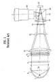
- FIG. 1 illustrates a related art image projector
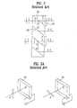
- FIG. 2 illustrates an operation of the polarization beam sprite array in the image projector in FIG. 1
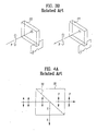
- FIGS. 3A and 3B illustrate operation of the image projector in FIG. 1
- FIGS. 4A and 4B illustrate operation of the polarization beam sprite prism in the image projector in FIG. 1
- FIG. 5 illustrates a lamp with an elliptic reflector.
- the related art image projector is provided with a lamp 1 for emitting beams of lights, a parabolic reflector 2 for reflecting the beams to forward of the lamp 1, and a polarized beam converter for transmitting an 'S' wave, and converting 'P' wave into 'S' wave and transmitting the converted 'S' wave among the beams from the parabolic reflector 2.
- the related art image projector also provided with first to third illumination lenses 10, 12, and 14 for focusing the beams polarized into a particular pole (i.e., the S wave) at the polarized beam converter, a color switch 16 for transmitting only a particular beam among the beams from the third illumination lens 14, and a polarization beam sprite prism 18 for supplying a particular color beam from the color switch 16 to a display 22, and the beam reflected at the display 22 to a projection lens 20.
- first to third illumination lenses 10, 12, and 14 for focusing the beams polarized into a particular pole (i.e., the S wave) at the polarized beam converter
- a color switch 16 for transmitting only a particular beam among the beams from the third illumination lens 14
- a polarization beam sprite prism 18 for supplying a particular color beam from the color switch 16 to a display 22, and the beam reflected at the display 22 to a projection lens 20.
- the display 22 displays a picture by reflecting the color beam from the polarization beam sprite prism 18 in response to a video signal, and the projection lens 20 enlarging the beam of the picture from the display 22, and projects to a screen at a distance.
- the beams of lights from the lamp 1 are incident on the polarized beam converter by the parabolic reflector 2.
- the polarized beam converter transmits the S wave, and converts and transmits P wave among the beams from the parabolic reflector 2.
- the polarized beam converter is provided with a first lens array 4, a second lens array 6, and a polarization beam sprite array 8 facing a light output surface of the second lens array 6.
- the first lens array 4, or the second lens array 6 focuses the beams of light including the P wave and the S wave to a plurality of focusing points.
- the first, or second lens array 4, or 6 has a matrix of a plurality of lenses.
- the polarization beam sprite array 8 transmits 'S' wave, and converts the P wave into the S wave, and transmits the converted S wave, both from the second lens array 6. To do this, the polarized beam sprite array 8 is provided with polarized beam split planes 24 and reflection planes 26 both sloped with respect to the optical output surface, and half wavelength plates 28 attached to optical output surface of the polarized beam split planes 24 as shown in FIG. 2.
- the polarized beam split plane 24 transmits only the P wave and reflects the S wave among the white beams from the second lens array 6.
- the P wave transmitted through the polarized beam split plane is converted into an S wave by the half wavelength plate 28.
- the S wave reflected at the polarized beam split plane 24 is reflected at the reflection plane 26 and forwarded as it is. That is, the entire beam of light including the P wave and the S wave passed through the polarization beam sprite array 8 is converted into the S wave.
- the beam converted into the S wave at the polarized beam converter are incident on the first to third illumination lenses 10, 12, and 14 in succession.
- the first to third illumination lenses 10, 12, and 14 focus the beams converted into the S wave onto the color switch 16.
- the color switch 16 splits red, green, and blue colors in succession so that one display cell has red, green, and blue colors in common. To do this, the color switch 16 filters a particular color beam according to a change of a voltage signal supplied from a voltage supply part (not shown). In this instance, the color beams passed through the color switch 16 are converted into the P wave from the S wave, and incident on the polarization beam sprite prism 18.
- the P wave color beam from the color switch 16 to the polarization beam sprite prism 18 transmits a split plane 30 in the polarization beam sprite prism 18, and incident on the display 22.
- the display 22 reflects the P wave color beam transmitted through the polarization beam sprite prism 18 according to a video signal, to produce a picture beam with picture information.
- the P wave color beam reflected at the display 22 is converted into the S wave.
- the picture beam converted into the S wave at the display 22 is reflected at the split plane 30 of the polarization beam sprite prism 18, and directed to the projection lens 20.
- the split plane 30 of the polarization beam sprite prism 18 transmits the P wave, and reflects the S wave as shown in FIGS. 4A and 4B. Accordingly, the polarization beam sprite prism 18 transmits the P wave from the color switch 16, and reflects the S wave from the display 22 toward the projection lens 20.
- the display 22 transmits the P wave color beam from the polarization beam sprite prism 18, as it is if there is an electrical signal applied thereto. Therefore, no beam of light is directed to the projection lens 20 when the electrical signal is applied to the display 22.
- the projection lens 20 enlarges the picture beam from the polarization beam sprite prism 18, and projects onto a screen at a distance therefrom.
- the color switch 16 for splitting the color beam from the beams of lights in the related art image projector has a poor light efficiency caused by poor light transmission.
- a color wheel may be employed in place of the color switch 16.
- the polarized beam converter in the related art image projector requires lens arrays each having a plurality of lenses.
- the lens arrays with the plurality of lenses cause optical losses between the lenses.
- the number of the lenses in the lens arrays may be reduced for reducing the optical loss, but that increases a thickness of the polarization array to push the cost up.
- assembly of the image projector requires much time.
- the related art image projector has the lamp with the parabolic reflector for providing parallel beams to the polarized beam converter.
- the lamp with the parabolic reflector has an optical efficiency poorer than a lamp with an elliptic reflector as shown in FIG. 5.
- the poor optical efficiency will be explained in detail assuming that a diameter of the parabolic reflector is Dp and a diameter of the elliptic reflector is De.
- the lamp with the parabolic reflector directs the beam of light forward in parallel, i.e., the parabolic reflector is required to have a slope for directing the beam from the lamp forward in parallel.
- the lamp with an elliptic reflector directs the beam of light such that the beam is focused at a plane in front of the lamp. Accordingly, the elliptic reflector is required to have a slope greater than the parabolic reflector so that the beam from the lamp is focused on the plane in front of the lamp. That is, because the lamp with the elliptic reflector can reflect more beams, the lamp with the elliptic reflector has an optical efficiency higher than the lamp with the parabolic reflector.
- the diameter of the elliptic reflector can be made smaller than the parabolic reflector, to reduce a size of the elliptic reflector.
- the lamp with the elliptic reflector can not be employed, that limits fabrication of a thinner image projector.
- the present invention is directed to an image projector that substantially obviates one or more of the problems due to limitations and disadvantages of the related art.
- An object of the present invention is to provide an image projector which can improve an optical efficiency.
- Another object of the present invention is to provide an image projector which permits fabrication of a thin image projector.
- the image projector includes a lamp for emitting beams of lights, a color wheel for splitting particular color beams in succession from the beams of lights, a rod lens for making distribution of the color beams from the color wheel uniform, a polarized beam converter for converting the color beams into beams of a particular pole, an optical system for focusing the color beams converted into beams of a particular pole, a display for producing a picture beam of a video signal according to the video signal by using the color beams from the optical system, a polarization beam sprite prism between the optical system and the display for transmitting the color beams from the optical system and reflecting the picture beams from the display, and a projection lens for enlarging, and projecting the picture beams.
- an image projector including a lamp for emitting beams of lights, a color wheel for splitting particular color beams in succession from the beams of lights, a rod lens for making distribution of the color beams from the color wheel uniform, a polarized beam converter for converting the color beams into beams of a particular pole, an optical system for focusing the color beams converted into beams of a particular pole, a display for producing a picture beam of a video signal according to the video signal by using the color beams from the optical system, and a projection lens for enlarging, and projecting the picture beams.
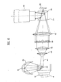
- FIG. 6 illustrates a diagram of an image projector in accordance with a first preferred embodiment of the present invention
- FIG. 7 illustrates a diagram of a distribution of beams focused by the illumination lenses in the image projector in FIG. 6,
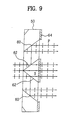
- FIGS. 8 and 9 illustrate operation of the polarization beam sprite prism
- FIG. 10 illustrates a diagram of an image projector in accordance with a second preferred embodiment of the present invention
- FIG. 11 illustrates a diagram of an image projector in accordance with a third preferred embodiment of the present invention
- FIG. 12 illustrates a diagram of an image projector in accordance with a fourth preferred embodiment of the present invention
- FIG. 13 illustrates a diagram of an image projector in accordance with a fifth preferred embodiment of the present invention
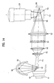
- FIG. 14 illustrates a diagram of an image projector in accordance with a sixth preferred embodiment of the present invention
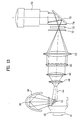
- FIG. 15 illustrates a diagram of an image projector in accordance with a seventh preferred embodiment of the present invention
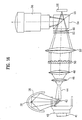
- FIG. 16 illustrates a diagram of an image projector in accordance with a eighth preferred embodiment of the present invention
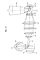
- FIG. 17 illustrates a diagram of an image projector in accordance with a ninth preferred embodiment of the present invention.
- the image projector in accordance with a first preferred embodiment of the present invention includes a lamp 36 for emitting beams of lights, an elliptic reflector 38 for reflecting the beams to forward of the lamp 36, a cylindrical color wheel 40 for transmitting a particular color beam among the beams of lights, a mirror 42 for deflecting a path of the color beam passed through the cylindrical color wheel 40, a rod lens 44 for making a distribution of the color beams from the mirror uniform, a polarized beam converter for converting the color beams from the rod lens 44 into beams of a particular pole, an illumination lens 52 for focusing the color beams converted into the particular pole at the polarized beam converter, and a polarization beam sprite prism 54 for supplying a color beam from the illumination lens 52 to the display 56 and beams transmitted from the display 56 to the projection lens 58.
- the display 56 transmits the color beams supplied from the polarization beam sprite prism 54 according to a video signal, to display a picture, and the projection lens 58 enlarges a beam of the picture from the display 56, and projects onto a screen at a distance.
- the beam of light from the lamp 36 is focused onto the cylindrical color wheel 40 by the elliptical reflector 38.
- the cylindrical color wheel transmits red, green, and blue beams of colors as the cylindrical color wheel rotates by a driving power of a motor 41.
- the beams color split by the cylindrical color wheel 40 are totally reflected at a mirror 42 and incident on the rod lens 44.
- the rod lens 44 makes the beams uniform so that the beam is distributed on the screen, uniformly. That is, a distribution of the beam entered into the rod lens 44 is made uniform by total reflection in the rod lens 44.
- the polarized beam converter converts the beams from the rod lens 44 into beams of a particular pole, and transmits the converted beams.
- the polarized beam converter includes a second illumination lens 46, and a third illumination lens 48 for focusing the beams from the rod lens 44 onto a particular location, and a polarization beam sprite array 50 facing an optical output surface of the third illumination lens 48.
- an area of the optical output surface of the rod lens 44 is required to be equal to, or smaller than an area of an optical input surface as expressed in the following inequality (1).
- the area of the optical output surface of the rod lens 44 is smaller than the area of the optical input surface, a degree of beam split is improved.
- the beams focused onto the plurality of focus dots by the second illumination lens 46 and the third illumination lens 48 are incident on the polarization beam sprite array 50.
- the polarization beam sprite array 50 converts the beam from the third illumination lens 48 into beams of a particular pole, and forwards. To do this, as shown in FIG. 8, the polarization beam sprite array 50 has polarization beam split planes 60 and polarization beam reflection planes 62, and half wavelength plates 64 attached to an optical output surface of the polarization beam split planes 60.
- the polarization beam split plane 60 transmits the P wave only, and reflects the S wave among the beams from the third illumination lens 48.
- the P wave passed through the polarization beam split plane 60 is converted into the S wave by the half wavelength plate 64.
- the S wave reflected at the polarization beam split plane 60 is reflected at the reflection plane 62, and forwarded. All the beams inclusive of the P wave passed through the polarization beam sprite array 50 and the S wave are converted into the S wave.
- the polarization beam sprite array 50 may also convert all the beams into the P wave the same with the related art polarization beam sprite array shown in FIG. 2.
- the beams from the third illumination lens 48 are concentrated to a central part. Accordingly, as shown in FIG. 9, two polarization beam split planes in a form of a triangle are provided in the center part of the polarization beam sprite array 50.
- the beams converted into the P wave at the polarization beam sprite array 50 are incident on the polarization beam sprite prism 54 by the first illumination lens 52.
- the beams of the S wave from the first illumination lens 52 to the polarization beam sprite prism 54 are reflected at the split plane 55, and incident on the display 56.
- the display 56 produces a picture beam with picture information by reflecting the beams of the S wave reflected at the polarization beam sprite prism 54 and incident thereon according to the video signal.
- the beams of S wave reflected at the display 56 are converted into the P wave by an electrical signal.
- the picture beams converted into the P wave at the display 56 transmit the split plane 55 in the polarization beam sprite prism 54, and incident on the projection lens 58.
- the polarization beam sprite prism 54 reflects the beams from the display 56.
- the incidence of the beams on the projections lens 58 is dependent on application of the electrical signal to the display 56.
- the projection lens 58 enlarges the picture beam from the polarization sprite prism 18, and projects to a screen at a distance.
- there are the beams of P wave from the polarization beam sprite array 50 there are half wavelength plates (not shown) between the polarization beam sprite array 50 and the polarization beam sprite prism 55, additionally.
- the half wavelength plate between the polarization beam sprite array 50 and the polarization beam sprite prism 55 converts the P wave from the polarization bean sprite array 50 into the S wave.
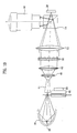
- a disk type color wheel may be employed in place of the drum form of cylindrical color wheel 40.
- the disk type color wheel 66 transmits red, green, and blue color beams in succession as the disk type color wheel 66 is rotated by a driving force of the motor 68. Operation of the disk type color wheel is the same with the first embodiment shown in FIG. 6.
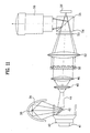
- FIG. 11 illustrates a diagram of an image projector in accordance with a third preferred embodiment of the present invention.
- the image projector in accordance with a third preferred embodiment of the present invention includes a polarization plate 53 between the first illumination lens 52 and the polarization prism 54.
- the polarizing plate 53 transmits only a beam of a particular pole from the first illumination lens 52. That is, the polarizing plate 53 removes noise beam of which polarization conversion is not done perfectly. The removal of the noise beam from the polarizing plate 53 improves contrast of the image projector.
- a 1/4 wavelength plate 57 may be provided between the polarization sprite prism 54 and the display 56 additionally, for preventing distortion of a polarized beam component of the beams transmitted through the polarization beam sprite prism 54, thereby improving contrast.
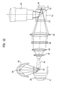
- FIG. 13 illustrates a diagram of an image projector in accordance with a fifth preferred embodiment of the present invention, wherein a transmission type display is provided.
- the image projector in accordance with a fifth preferred embodiment of the present invention further includes the transmission type display 70, polarization plates 72, and 74 fitted in front, and rear of the transmission type display 70, and a mirror 76 for directing the beams passed through the transmission type display 70 to the projection lens 78, in addition to the system of the first embodiment.
- the transmission type display 70 receives beams of the lights from the first illumination lens 52, and transmits the beams therethrough according to a video signal, for producing a picture beam loaded with picture information.
- the polarizing plate 72 in front of the transmission type display only transmits a beam of particular pole among the beams from the first illumination lens 52, and the polarizing plate 74 in rear of the transmission type display 70 only transmits a beam of a particular pole among the picture beam from the transmission type display 70.
- the picture beam passed through the polarizing plate 74 is incident on the mirror 76, and the mirror 76 supplies the picture beam supplied thereto to the projection lens 78.
- FIG. 14 illustrates a diagram of an image projector in accordance with a sixth preferred embodiment of the present invention.
- the image projector includes a half wavelength plate 80 fitted between the first illumination lens 52 and the polarization beam sprite prism 54.
- the half wavelength plate 80 converts the S wave from the illumination lens 52 into the P wave. That is, the converted P wave is incident on the polarization beam sprite prism 54, transmits the split plane 55, and is directed to the display 56. According to an electric characteristic of the display 56, the P wave incident on the display 56 is converted into the S wave, reflected at the polarization beam sprite prism 54 and the split plane 55, and incident on the projection lens, or the P wave not converted into the S wave transmits the split plane 55, not being incident on the projection lens 58.
- the present invention may employ a disk type color wheel 66 as shown in FIG. 15 in place of the cylindrical color wheel of a drum form.
- the disk type color wheel 66 transmits red, green, and blue color beams in succession as the motor 68 rotates the color wheel 66.
- Other operations of the seventh embodiment projector are identical to the sixth embodiment explained in association with FIG. 14.
- FIG. 16 illustrates a diagram of an image projector in accordance with an eighth preferred embodiment of the present invention.
- the image projector includes a polarizing plate 53 fitted between the first illumination lens 52 and the half wavelength plate 80.
- the polarizing plate 53 transmits a beam of a particular pole among the beams from the first illumination lens 52. That is, the polarizing plate 53 removes noise beams which are not converted into polarized beams at the illumination system, perfectly. The removal of the noise beams at the polarizing plate 53 improves a contrast of the projector.
- the projector of the present invention may have a 1/4 wavelength plate 57 between the polarization beam sprite prism 54 and the display 56 additionally, for preventing distortion of a polarized beam component of the beams transmitted through the polarization beam sprite prism 54, thereby improving a contrast.
- the projectors of the foregoing embodiments of the present invention permit to employ the lamp with the elliptic reflector because the rod lens requires focusing of beams thereon, thereby providing an optical efficiency higher than the related art projector, and permitting to fabricate a projector thinner than the related art.
- the projector of the present invention permits to improve an optical efficiency of the projector, and fabricate a projector thinner than the related art because the beams are focused onto the rod lens that permits addition of a color wheel without addition of other optical system. Furthermore, the focusing of beams by using the illumination lenses only without the lens array used in the related art permits to prevent the optical loss from the lens array.
Landscapes
- Engineering & Computer Science (AREA)
- Multimedia (AREA)
- Signal Processing (AREA)
- Physics & Mathematics (AREA)
- General Physics & Mathematics (AREA)
- Projection Apparatus (AREA)
- Video Image Reproduction Devices For Color Tv Systems (AREA)
Abstract
Description
Claims (23)
- An image projector comprising:a lamp for emitting beams of lights;a color wheel for splitting particular color beams in succession from the beams of lights;a rod lens for making distribution of the color beams from the color wheel uniform;a polarized beam converter for converting the color beams into beams of a particular pole;an optical system for focusing the color beams converted into beams of a particular pole;a display for producing a picture beam of a video signal according to the video signal by using the color beams from the optical system;a polarization beam sprite prism between the optical system and the display for reflecting the color beams from the optical system and transmitting the picture beams from the display; and,a projection lens for enlarging, and projecting the picture beams.
- An image projector as claimed in claim 1, wherein the light source includes an elliptic reflector for focusing the beams of lights onto a surface in front of the light source.
- An image projector as claimed in claim 1, wherein the color wheel is a cylindrical color wheel having a plurality of color filters integrated into a cylinder form.
- An image projector as claimed in claim 3, further comprising a mirror for directing the color beams split at the cylindrical type color wheel onto the rod lens.
- An image projector as claimed in claim 1, wherein the color wheel is a disk type color wheel having a plurality of color filters integrated into a disk form.
- An image projector as claimed in claim 1, wherein the rod lens has an optical input surface with an area equal to, or greater than an optical output surface thereof.
- An image projector as claimed in claim 1, wherein the polarized beam converter includes;at least one illumination lens for receiving the color beams from the rod lens and focusing onto a plurality of beam focusing points, anda polarization beam sprite array for converting the color beams into beams of a particular pole.
- An image projector as claimed in claim 7, wherein the polarization beam sorite array receives beams inclusive of a P wave and an S wave, and transmitting the S wave and converting the P wave into the S wave and transmitting the converted S wave.
- An image projector as claimed in claim 7, wherein the polarization beam sprite array receives beams inclusive of a P wave and an S wave, and transmitting the P wave and converting the S wave into a P wave and transmitting the converted P wave.
- An image projector as claimed in claim 9, further comprising a half wavelength plate between the polarization beam sprite array and the polarization beam sprite prism for converting the S wave into the P wave, or vice versa.
- An image projector as claimed in claim 1, wherein the optical system includes at least one illumination lens.
- An image projector as claimed in claim 1, further comprising a polarizing plate between the optical system and the polarization beam sprite prism for removing noise beams.
- An image projector as claimed in claim 1, further comprising a 1/4 wavelength plate between the polarization beam sprite prism and the display for preventing a component of polarized beams transmitted through the polarization beam sprite prism from being distorted.
- An image projector as claimed in claim 1, wherein the display is a reflection type display.
- An image projector comprising:a lamp for emitting beams of lights;a color wheel for splitting particular color beams in succession from the beams of lights;a rod lens for making distribution of the color beams from the color wheel uniform;a polarized beam converter for converting the color beams into beams of a particular pole;an optical system for focusing the color beams converted into beams of a particular pole;a display for producing a picture beam of a video signal according to the video signal by using the color beams from the optical system; and,a projection lens for enlarging, and projecting the picture beams.
- An image projector as claimed in claim 15, wherein the display is a transmission type display.
- An image projector as claimed in claim 16, wherein the display includes polarizing plates fitted in front and rear of the display.
- An image projector as claimed in claim 15, further comprising a mirror between the display and the projection lens for directing the picture beams supplied from the display to the projection lens.
- An image projector as claimed in claim 15, wherein the color wheel is a cylindrical color wheel having a plurality of color filters integrated into a cylinder form.
- An image projector as claimed in claim 19, further comprising a mirror for directing the color beams split at the cylindrical type color wheel onto the rod lens.
- An image projector as claimed in claim 15, wherein the color wheel is a disk type color wheel having a plurality of color filters integrated into a disk form.
- An image projector as claimed in claim 15, wherein the rod lens has an optical input surface with an area equal to, or greater than an optical output surface thereof.
- An image projector as claimed in claim 15, wherein the polarized beam converter includes;at least one illumination lens for receiving the color beams from the rod lens and focusing onto a plurality of beam focusing points, anda polarization beam sprite array for converting the color beams into beams of a particular pole.
Applications Claiming Priority (2)
| Application Number | Priority Date | Filing Date | Title |
|---|---|---|---|
| KR2000084712 | 2000-12-28 | ||
| KR20000084712 | 2000-12-28 |
Publications (2)
| Publication Number | Publication Date |
|---|---|
| EP1220548A2 true EP1220548A2 (en) | 2002-07-03 |
| EP1220548A3 EP1220548A3 (en) | 2003-08-20 |
Family
ID=19703817
Family Applications (1)
| Application Number | Title | Priority Date | Filing Date |
|---|---|---|---|
| EP01131003A Withdrawn EP1220548A3 (en) | 2000-12-28 | 2001-12-28 | Image projector |
Country Status (4)
| Country | Link |
|---|---|
| US (1) | US6802610B2 (en) |
| EP (1) | EP1220548A3 (en) |
| KR (1) | KR100451733B1 (en) |
| CN (1) | CN1171112C (en) |
Cited By (1)
| Publication number | Priority date | Publication date | Assignee | Title |
|---|---|---|---|---|
| EP1577700A3 (en) * | 2004-03-19 | 2011-10-05 | Philips Lumileds Lighting Company LLC | Light emitting diode with polarised light output |
Families Citing this family (16)
| Publication number | Priority date | Publication date | Assignee | Title |
|---|---|---|---|---|
| EP1234869A4 (en) | 1999-11-29 | 2004-07-07 | Iq Ct Co Ltd | Cleaning composition and method for preparing the same |
| KR100397427B1 (en) * | 2000-12-28 | 2003-09-13 | 엘지전자 주식회사 | Polarizing Light Converting Apparatus |
| KR100839285B1 (en) * | 2002-04-23 | 2008-06-17 | 엘지전자 주식회사 | Projection device using color drum |
| JP4100276B2 (en) * | 2003-07-04 | 2008-06-11 | セイコーエプソン株式会社 | Lighting device and projector |
| KR100617196B1 (en) * | 2004-06-24 | 2006-09-01 | 엘지전자 주식회사 | Single plate illumination optical system and projection display device using the same |
| CN1847971B (en) * | 2005-04-04 | 2010-05-12 | 中华映管股份有限公司 | LCD Projection Display |
| KR100686882B1 (en) * | 2005-04-04 | 2007-02-26 | 엘지전자 주식회사 | Optical system of the projection display |
| US20070116405A1 (en) * | 2005-05-11 | 2007-05-24 | Kane David M | Optical-radiation projection |
| JP2007102101A (en) * | 2005-10-07 | 2007-04-19 | Canon Inc | Illumination optical system and image projection apparatus having the same |
| KR20070082799A (en) * | 2006-02-17 | 2007-08-22 | 엘지전자 주식회사 | Brightness Control Method of Projection Image Display Device and Image Display Device |
| TWM337114U (en) * | 2007-06-23 | 2008-07-21 | Young Optics Inc | Projection apparatus and illumination system thereof |
| CN101749566A (en) * | 2008-12-12 | 2010-06-23 | 红蝶科技(深圳)有限公司 | Semiconductor lighting device and micro projection optical engine using same |
| CN104769350A (en) * | 2012-11-01 | 2015-07-08 | 日立麦克赛尔株式会社 | Light source device and projection-type image display device |
| WO2014073043A1 (en) * | 2012-11-07 | 2014-05-15 | 日立マクセル株式会社 | Projecting video display device |
| CN103186027A (en) * | 2013-04-01 | 2013-07-03 | 电子科技大学 | Dodging device for micro-projector |
| EP3617584B1 (en) * | 2017-04-24 | 2025-04-02 | Stanley Electric Co., Ltd. | Lamp unit, and vehicular lighting system |
Family Cites Families (25)
| Publication number | Priority date | Publication date | Assignee | Title |
|---|---|---|---|---|
| JPS605722B2 (en) * | 1977-06-24 | 1985-02-13 | 株式会社東芝 | Track device for normal conductive magnetic levitation vehicle |
| JPH05257110A (en) * | 1992-03-13 | 1993-10-08 | Sharp Corp | Projection type liquid crystal display device |
| US5517340A (en) * | 1995-01-30 | 1996-05-14 | International Business Machines Corporation | High performance projection display with two light valves |
| WO1997045768A1 (en) * | 1996-05-29 | 1997-12-04 | Seiko Epson Corporation | Projection display |
| US6497485B1 (en) * | 2000-01-20 | 2002-12-24 | Seiko Epson Corporation | Image projection system having uniform brightness |
| TW358890B (en) | 1996-06-25 | 1999-05-21 | Seiko Epson Corp | Polarizing converter, polarizing lighting, display and projection using these elements |
| GB9621635D0 (en) | 1996-10-17 | 1996-12-11 | Hawes Edward M | Light projection system |
| US5884991A (en) * | 1997-02-18 | 1999-03-23 | Torch Technologies Llc | LCD projection system with polarization doubler |
| US5863125A (en) * | 1998-01-30 | 1999-01-26 | International Business Machines Corporation | High efficiency two-SLM projector employing total-internal-reflection prism |
| JP3622500B2 (en) * | 1998-05-20 | 2005-02-23 | 株式会社富士通ゼネラル | Liquid crystal projector |
| JP2000028960A (en) | 1998-07-10 | 2000-01-28 | Nec Corp | Projector |
| JP2000034723A (en) | 1998-07-21 | 2000-02-02 | Shibayama Kenchiku Kenkyusho:Kk | Retaining wall structure |
| US5984478A (en) * | 1998-07-29 | 1999-11-16 | International Business Machines Corporation | Dynamic optical compensation for color sequential projection display |
| US6266105B1 (en) * | 1998-07-31 | 2001-07-24 | Philips Electornics North America Corporation | Color projection system incorporation electro-optic light modulator and rotating light-reflective element |
| GB2340619A (en) | 1998-08-11 | 2000-02-23 | Sharp Kk | Liquid crystal projector with non-uniform lenslet arrays |
| US6005722A (en) * | 1998-09-04 | 1999-12-21 | Hewlett-Packard Company | Optical display system including a light valve |
| US6394606B1 (en) | 1998-09-29 | 2002-05-28 | Sony Corporation | Projection-type display device |
| US6343862B1 (en) * | 1998-11-20 | 2002-02-05 | Minolta Co., Ltd. | Projecting image display device |
| JP3299216B2 (en) * | 1999-01-29 | 2002-07-08 | エヌイーシービューテクノロジー株式会社 | Video projection device |
| JP3522591B2 (en) * | 1999-06-04 | 2004-04-26 | シャープ株式会社 | Image display device |
| JP3571582B2 (en) * | 1999-06-18 | 2004-09-29 | シャープ株式会社 | Image display device |
| US6642969B2 (en) * | 1999-12-30 | 2003-11-04 | Texas Instruments Incorporated | Color wheel for a falling raster scan |
| JP3823659B2 (en) * | 2000-02-04 | 2006-09-20 | セイコーエプソン株式会社 | projector |
| US6398368B2 (en) * | 2000-06-09 | 2002-06-04 | Acer Communications And Multimedia Inc. | Light pipe for a projector system |
| US6547396B1 (en) * | 2001-12-27 | 2003-04-15 | Infocus Corporation | Stereographic projection system |
-
2001
- 2001-12-24 KR KR10-2001-0084234A patent/KR100451733B1/en not_active Expired - Fee Related
- 2001-12-27 US US10/026,541 patent/US6802610B2/en not_active Expired - Lifetime
- 2001-12-28 EP EP01131003A patent/EP1220548A3/en not_active Withdrawn
- 2001-12-28 CN CNB011448474A patent/CN1171112C/en not_active Expired - Fee Related
Cited By (1)
| Publication number | Priority date | Publication date | Assignee | Title |
|---|---|---|---|---|
| EP1577700A3 (en) * | 2004-03-19 | 2011-10-05 | Philips Lumileds Lighting Company LLC | Light emitting diode with polarised light output |
Also Published As
| Publication number | Publication date |
|---|---|
| KR20020055381A (en) | 2002-07-08 |
| US20020085180A1 (en) | 2002-07-04 |
| EP1220548A3 (en) | 2003-08-20 |
| US6802610B2 (en) | 2004-10-12 |
| KR100451733B1 (en) | 2004-10-08 |
| CN1362632A (en) | 2002-08-07 |
| CN1171112C (en) | 2004-10-13 |
Similar Documents
| Publication | Publication Date | Title |
|---|---|---|
| US6536902B2 (en) | Projector | |
| US6802610B2 (en) | Image projector | |
| US6439724B1 (en) | Color projector | |
| EP1052856A2 (en) | Reflection type color projector | |
| KR100381050B1 (en) | Optical System Of Liquid Crystal Projector | |
| KR100381051B1 (en) | Optical System Of Liquid Crystal Projector | |
| EP1220011A2 (en) | Projector with polarization converter | |
| KR100433211B1 (en) | Optical illumination system of projector using optical device uniforming amount of light and polarization | |
| US6052214A (en) | System and method for producing an enhanced image | |
| KR100352973B1 (en) | Optical System Of Liquid Crystal Projector Using Two Lamps | |
| US20040207769A1 (en) | Projection display device | |
| KR20040022976A (en) | A projection display system | |
| US20050041288A1 (en) | Polarization conversion module and polarization conversion method thereof | |
| JP2768345B2 (en) | LCD projector | |
| KR100342830B1 (en) | Optical System Of Liquid Crystal Projector | |
| KR100342829B1 (en) | Optical System Of Liquid Crystal Projector | |
| JP3047464U (en) | Multi-level light source device and image scanner using the same | |
| KR100438282B1 (en) | Apparatus and Method for adjusting width of a beam | |
| KR100744499B1 (en) | Illumination system of LCD projector | |
| JPH0777667A (en) | Image transfer device | |
| KR20000074554A (en) | Polarizing Light Converting Apparatus Using Cholesteric Liquid Crystal and Liquid Crystal Projector Usign The same | |
| JPH11160789A (en) | LCD projector optical system | |
| JP2001133884A (en) | Illumination optics | |
| KR20020064101A (en) | Optical system of liquid crystal projector |
Legal Events
| Date | Code | Title | Description |
|---|---|---|---|
| PUAI | Public reference made under article 153(3) epc to a published international application that has entered the european phase |
Free format text: ORIGINAL CODE: 0009012 |
|
| AK | Designated contracting states |
Kind code of ref document: A2 Designated state(s): AT BE CH CY DE DK ES FI FR GB GR IE IT LI LU MC NL PT SE TR |
|
| AX | Request for extension of the european patent |
Free format text: AL;LT;LV;MK;RO;SI |
|
| PUAL | Search report despatched |
Free format text: ORIGINAL CODE: 0009013 |
|
| AK | Designated contracting states |
Designated state(s): AT BE CH CY DE DK ES FI FR GB GR IE IT LI LU MC NL PT SE TR |
|
| AX | Request for extension of the european patent |
Extension state: AL LT LV MK RO SI |
|
| 17P | Request for examination filed |
Effective date: 20040220 |
|
| AKX | Designation fees paid |
Designated state(s): DE FR GB NL |
|
| 17Q | First examination report despatched |
Effective date: 20071106 |
|
| STAA | Information on the status of an ep patent application or granted ep patent |
Free format text: STATUS: THE APPLICATION HAS BEEN WITHDRAWN |
|
| 18W | Application withdrawn |
Effective date: 20080513 |