BACKGROUND OF THE INVENTION
Field of the Invention:
The invention relates generally to software. More particularly, the
present invention relates to software for creating digital photo albums.
Description of the Related Art:
Modern photography is moving into the digital age. Even though a
large part of the market for photography still utilizes conventional film and
processing, the ability to obtain digital files from conventional film is rapidly adapting
the conventional film market into the digital image arena. In addition, with the broad
acceptance of digital cameras, as well as broad utilization of digital images in Internet
applications, the volume of commercial and consumer produced digital image files has
increased dramatically in recent years. Suppliers now routinely deliver digital image
files to users. Such files may be delivered on storage media, like photo CD's and so
forth, or may be delivered via the Internet or through e-mail. The provision of digital
images in an organized format, including the preparation of digital image photo
albums, is now available in the marketplace, as consumers desire to receive and
present their images in a most favorable light. However, there has yet to be
introduced an automated system that presents digital images in sophisticated creatively
composed fashions.
There presently exist several software applications, which assist the user in
manual creation of digital photo albums. In general, these applications provide the
user with a straightforward means of accomplishing the basic task of image
organization and page layout, so called 'albuming'. The drawback with such
applications is that they require a large amount of user interaction, which does not
yield much improvement over the conventional, paper based albuming techniques of
the past. Therefore, the task is less likely to be completed due to the significant
amount of effort required to accomplish it.
Automated albuming systems that offer limited automated layout
functions are known in the art. Eastman Kodak Company has developed digital
graphic album applications, such as the Kodak Picture Page software, which allow a
user to organize digital graphics images into album pages. Typically, users organize
images by dates and times, places, subject and so forth. Such software allows the
user to annotate the images by entering text, or other data, describing the image. One
common approach to automated layout is the use of templates. In this approach,
predefined layouts with empty areas are filled in with user images. Thus, the size,
placement, rotation, and framing of the images on the page are predetermined. A user
or system merely needs to specify which images should be placed in which empty
area to complete an album page. This approach is also widely used by many graphic
layout design tools (such as Quark) and by Kodak® PicturePage® Software.
Templates provide a straightforward and working solution to the layout problem.
However, this solution is somewhat limiting as the choice of layouts is bounded by
the collection of available templates. Variation in page layout design can only be
achieved by the addition of new templates.
The real challenge in automatic generation of page layouts is allowing a
level of creativity in the layouts produced. With the introduction of scrapbooking as a
social activity, there has been a recent resurgence of interest in capturing memories
and telling stories using scrapbooks. The albums produced by people in these
communities can range from extremely basic, where images are laid out using a fixed
grid or template, to extremely complex, where images are seemingly scattered
randomly on a page. In such layouts, it is very difficult to define, in an objective
fashion, what the layout approach is.
Consequently, a need exists in the art for an automated system and/or
method of organizing and generating album and page layouts of digital images.
SUMMARY OF THE INVENTION
The need in the art is addressed by the systems and methods of the
present invention. The Automatic Albuming System taught by the present invention
is unique, in part, because it produces album pages automatically with minimal input
from the user. In an illustrative embodiment, a digital image album layout system is
taught. The system comprises a page creator module that has a first genetic engine
operable to execute genetic evolution calculations on a first genetic population of
image criteria. The page creator module also has a page evaluation module that is
operable to test the first genetic population for fitness to album preference criteria.
The system also has an image placement module with a second genetic engine that is
operable to execute genetic evolution calculations on a second genetic population of
page layout criteria. The image placement module also has a layout evaluation
module that is operable to test the second genetic population for fitness to page
preference criteria.
The present invention teaches an automated album layout method.
The method involves the use of a set of inputs including digital images, graphics, and
other 2-dimensional objects. The inventive method comprises the steps of evaluating
a grouping of the image objects for distribution into a number of album pages
according to a fitness function's parameters of a genetic engine and, assigning each
image object to a page based on user preferences, including at least one of: balance,
emphasis, chronology, and unity. Then, the page is displayed for user viewing and
distribution refining the based on further user action.
The present invention also teaches an automated layout and
presentation method responsive to a set of inputs containing digital images, graphics,
and other two-dimensional objects. This method comprises the steps of evaluating
the 'x' and 'y' position coordinates, scale and rotation of each of the input images
objects within a page according to fitness function parameters in a genetic engine.
Then, a page layout is created based on user preferences including at least one of:
white space, overlap, rotation, spatial balance, rotational balance, border symmetry,
and emphasis. Then, the page layout is displayed for user viewing, and refining the
page layout based on further user action. Finally, the page layout is formatted for
printing.
In an illustrative embodiment, a system for assigning images to album
pages is taught. The system includes a mechanism for specifying an initial set of
image page assignments to a genetic population and a genetic engine operable to
evolve the genetic population to produce a present set of image page assignments.
The system also includes a page evaluation module operable to test the present set of
image page assignments according to an album fitness function to determine an album
score and a mechanism for outputting the present set of image page assignments if the
album score meets an album threshold value.
In another illustrative embodiment, a system for arranging images on
an album page is taught. This system includes a mechanism for specifying an initial
set of image placement parameters to a genetic population and a genetic engine
operable to evolve the genetic population to produce a present set of image placement
parameters. The system also includes a layout evaluation module, operable to test the
present set of image placement parameters with a page fitness function to determine a
page score, and a mechanism for outputting the image placement parameters if the
page score meets a page threshold value.
BRIEF DESCRIPTION OF THE DRAWINGS
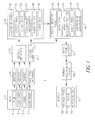
Fig. 1 is an overview diagram of an Albuming Automation System in
an illustrative embodiment of the present invention.
Fig. 2 is a flow chart of a genetic algorithm process in an illustrative
embodiment of the present invention.
Fig. 3 is a tree diagram of a genetic crossover in an illustrative
embodiment of the present invention.
Fig. 4 is a tree diagram of a genetic mutation in an illustrative
embodiment of the present invention.
Fig. 5 is an array diagram of a genetic crossover in an illustrative
embodiment of the present invention.
Fig. 6 is an array diagram of a genetic mutation in an illustrative
embodiment of the present invention.
Fig. 7 is a system architecture diagram of the page layout module
according to an illustrative embodiment of the present invention.
Fig. 8 is a genome diagram of the page creation module according to
an illustrative embodiment of the present invention.
Fig. 9 is a diagram illustrating the encoding of the genome by the page
creation module according to an illustrative embodiment of the present invention.
Fig. 10 is a diagram of an exemplary set of images for manipulation by
the page creation module in an illustrative embodiment of the present invention.
Fig. 11 is a page layout example according to an illustrative
embodiment of the present invention.
Fig. 12 is a page layout example according to an illustrative
embodiment of the present invention.
Fig. 13 is a page layout example according to an illustrative
embodiment of the present invention.
Fig. 14 is a page layout example according to an illustrative
embodiment of the present invention.
Fig. 15 is a page layout example according to an illustrative
embodiment of the present invention.
Fig. 16 is a page layout example according to an illustrative
embodiment of the present invention.
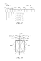
Figure 17 is a diagram of the genome encoding for the image
placement module in an illustrative embodiment of the present invention.
Figure 18 is a diagram of the encoding of image rotation information
in an illustrative embodiment of the present invention.
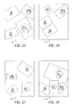
Figure 19 is an image used in the image placement examples according
to an illustrative embodiment of the present invention.
Figure 20 is an image used in the image placement examples according
to an illustrative embodiment of the present invention.
Figure 21 is an image used in the image placement examples according
to an illustrative embodiment of the present invention.
Figure 22 is an image used in the image placement examples according
to an illustrative embodiment of the present invention.
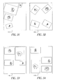
Figure 23 is a diagram of an image placement example according to an
illustrative embodiment of the present invention.
Figure 24 is a diagram of an image placement example according to an
illustrative embodiment of the present invention.
Figure 25 is a diagram of an image placement example according to an
illustrative embodiment of the present invention.
Figure 26 is a diagram of an image placement example according to an
illustrative embodiment of the present invention.
Figure 27 is a diagram of an image placement example according to an
illustrative embodiment of the present invention.
Figure 28 is a diagram of an image placement example according to an
illustrative embodiment of the present invention.
Figure 29 is a diagram of an image placement example according to an
illustrative embodiment of the present invention.
Figure 30 is a diagram of an image placement example according to an
illustrative embodiment of the present invention.
Figure 31 is a diagram of an image placement example according to an
illustrative embodiment of the present invention.
Figure 32 is a diagram of an image placement example according to an
illustrative embodiment of the present invention.
Figure 33 is a diagram of an image placement example according to an
illustrative embodiment of the present invention.
Figure 34 is a diagram of an image placement example according to an
illustrative embodiment of the present invention.
Figure 35 is a diagram of an image placement example according to an
illustrative embodiment of the present invention.
Figure 36 is a diagram of an image placement example according to an
illustrative embodiment of the present invention.
Figure 37 is a diagram of an image placement example according to an
illustrative embodiment of the present invention.
Figure 38 is a diagram of an image placement example according to an
illustrative embodiment of the present invention.
DESCRIPTION OF THE INVENTION
While the present invention is described herein with reference to
illustrative embodiments for particular applications, it should be understood that the
invention is not limited thereto. Those having ordinary skill in the art and access to
the teachings provided herein will recognize additional modifications, applications,
and embodiments within the scope thereof and additional fields in which the present
invention would be of significant utility.
The principle objective of albuming automation is to automate the
album production process using various image science algorithms and techniques.
The final step of this automated process is to layout images within an album in a
manner pleasing to the user.
The present invention teaches an innovative and flexible system for
automatic album page layout that makes advantageous use of genetic algorithms. The
system is divided into two modules, a Page Creator Module which is responsible for
distributing images amongst various album pages and an Image Placement Module
which positions images on individual pages. Each module incorporates basic graphic
design principles such as balance, emphasis, rhythm, and unity, in determining fitness
for page layout solutions.
A complete albuming automation system utilizes various image
science algorithms and techniques including advanced event clustering, dud detection,
image appeal and automatic page layout. In an illustrative embodiment, the emphasis
of such a system is for a "DAFY" (Do-it-All-For-You) like product, where the user
inputs a collection of images and the system produces an album (a collection of
images) with minimal input from the user. It will be understood by those of ordinary
skill in the art, that the term 'images' encompasses a much broader scope than the
conventional photograph, even though the album concept stems from the traditional
photographic album. In the modern digital world, images include computer generated
graphics, bitmaps, photographs, computer altered photographs, video still frames,
scanned images, various forms or artwork, text, background materials, and even video
clips, animation, and computer generated time variant materials.
An overall functional diagram of an illustrative embodiment Albuming
Automation System ('AAS') 2 is depicted in Fig. 1. One important function of the
AAS 2 is to layout images within an album page. This function is the last major
operation before an album page can be rendered for display, printing, or transfer to
any another medium. In the illustrative embodiment of Fig. 1, the AAS 2 receives
input 4 from one of a variety of image sources, which includes conventional film 6,
flash memory cards 8, video media 10, and other images sources as are understood by
those of ordinary skill in the art. Another basic input to the AAS 2 is the user
specified preferences 12, which will be more fully discussed hereinafter. Film 6 input
is first digitized 14 for subsequent processing. Flash memory card media 8 is
decoded 16. Video media 10 is also digitized 18. Once a common digital format is
established, the image information is processed to recover any metadata information
22 that may be available. Metadata can be found in Internet originated images, and
may be supplied by the user or other individual. For example, APS cameras allow for
inclusion of metadata related to the date and time the image was taken, the image
format, and other technical parameters related to the exposure of the image. User
preferences 12 are stored in a user preference database 20 and are subsequently
decoded 24 for use in processing the user preferences along with the image
information. By maintaining a database of user preferences, subsequent use of the
system by a particular user can be made more efficient and convenient. The system is
able to recall the user preferences and apply them to new batches of images, and can
offer the user an opportunity to amend previous preferences as well.
The core processing of the AAS 2 includes several functions 26 that
discriminate images and information for subsequent page layout. These include
clustering of images by event 28, detection of dud images 30, detection of duplicate
images 32, recognition of facial features and certain other objects 34, audio to text
conversion 36, and video summarization 38. The reduced and refined image
information is then coupled to a second group of core process functions 40 that
further refine the image content information. These functions include selection of the
best image per page 42, automatic image cropping 44, association of particular
images with ancillary content 46, association with event description information 48,
and association with caption and annotation information 50. The refined image
information is coupled to the automatic page layout process 52, which will be more
fully described hereinafter. Page layout data is coupled to an output format module
54 that further organizes the output from the automatic page layout module 52.
Finally, the output of the AAS 2 is produced at module 56 in the form of single page
images 58, entire albums of images 60, Picture CD media, or other photo delivery
media as are understood by those of ordinary skill in the art.
The present invention teaches a flexible system for generation of
album page layouts. The system makes use of genetic algorithms, a class of search
and optimization algorithms that are based on the concepts of biological evolution.
For a more detailed reference to genetic algorithms, see; J. Holland, Adaptation in
Natural and Artificial Systems. The University of Michigan Press, Ann Arbor, 1975,
and, D. Goldberg, Genetic Algorithms in Search, Optimization, and Machine
Learning, Addison-Wesley, 1989, the contents of which are hereby incorporated by
reference thereto. The system is comprised of two major modules, the first that
distributes images amongst a set of album pages, and the second that positions the
images on each individual page. These modules are called the Page Creator Module
and the Image Placement Module respectively. Each module takes a genetic
approach to its task.
The overall function of the Page Layout System 124 is
straightforward. Given a set of images to be placed in an album, a page layout
algorithm must distribute the images amongst a set of pages and then layout the
images on each individual page. Working within the framework of the AAS, the
following information is available to the page layout system 124 on an image by
image basis:
- Event Clustering - Images are grouped by event and sub-event
- Dud/Duplicate Detection - Duplicate and dud detection are performed on the
images prior to being submitted to the page layout system. Thus, the list of
images supplied as input to the page layout process represent all the images
that will be contained within the final album.
- Emphasis/Image Appeal - Images have an associated image appeal or
emphasis value. This value is a measure of relative importance and is be used
as a guide in determining the emphasis that an image will be given when
placing it on an album page.
- Chronology - The chronology of the images to be placed in the album is
known.
The page layout system 124 performs two separate, yet equally
important tasks. Page creation 126, given a set of images, the system distributes these
images amongst a set of album pages, such that each image is assigned a page upon
which the image will appear. And, image placement 132, once the images have been
assigned to pages, each individual page is laid out by positioning the images assigned
to it. Therefore, for each image, placement, rotation, and scaling of the image on the
page are assigned.
With regard to album layout according to the present invention, an
important advantage is that the Automated Albumimg System produces albums that
more closely resemble scrapbooks as opposed to a simple collection of pictures.
Achieving this goal in an automated fashion is a significant accomplishment because
the means by which creative scrapbookers generate page layouts for their albums is
usually not easily expressed in an objective fashion. The creation of a scrapbook is
primarily a subjective and artistic task. Few, if any, concrete rules exist in the
scrapbook generation process, and those that do, tend to be individual based on
personal preferences. The subjective nature of creative page layout poses a real
challenge to any page layout system. In particular, template based layout approaches
are somewhat limiting since the range of possibilities for a page layout are bounded
by the collection of available templates.
The present invention employs a novel approach to page layout by employing
genetic algorithms, which are a class of adaptive methods that can be used to solve
search and optimization problems involving large search spaces. The search is
performed using a simulated evolution (survival of the fittest). These algorithms
maintain and manipulate "generations" of potential solutions or "populations". With
each generation, the best solutions (as determined by a problem specific fitness
function) are genetically manipulated to form the solution set for the following
generation. As in real evolution, solutions can be combined (via mating/crossover) or
undergo random mutation. In addition, inferior solutions can, by chance, survive
from generation to generation.
The genetic algorithm search process is performed in an iterative
manner as illustrated in Fig. 2. The process starts at step 64, and then an initial
population of solutions is generated at step 66. This initialization is typically done
through random placement of the image population, although there is nothing
prohibiting in using some sort of heuristic for this process. Once a population is
established, individual solutions are judged at step 68 based on a fitness function and
suitable individuals are chosen for mating and mutation. Next, at steps 70 and 72,
crossover and mutation are performed on the chosen solution, resulting in a number
of new individuals in the population. These new individuals are generated using the
genetic operators of mutation, step 70, and crossover, step 72. A new generation of
solutions is then created from these newly generated offspring by inserting them into
the population at step 74. It is noted that there are a number of different variants used
when constructing a new generation of solutions. In some cases, individuals chosen
for mating and mutation are included in this next generation of solutions. Note also,
that unlike biological mating, new solutions can be generated from the crossover of
two or more suitable individuals. The process is iterated until a defined stopping
criterion is met at step 76, in which case the process finishes at step 78. The stopping
criteria will be more fully discussed hereinafter.
When applying a genetic algorithm to a given problem, three major
tasks must be performed:
Common genome data structures used in genetic algorithms includes lists, arrays, and
trees. 2) Definition of Genetic Operators - New solutions are created via crossover
and mutation of individuals from previous generations. Given a particular genome
structure, the means for performing these operations must be defined. During
crossover, one or more children solutions are derived from two or more parents.
With mutation, new individuals are generated by mutation of a single solution. There
are standard crossover and mutation operators available for genomes encoded using
commonly used data structures like lists, arrays, and trees. 3) Fitness - The most challenging and application specific task in applying
genetic algorithms to a problem domain is in the definition of a fitness function. The
fitness function is responsible for judging individual solutions and returning a score
based on its evaluation. In essence, the fitness function defines the difference
between a good solution to a problem and a bad one. Much care must be taken in
defining the fitness function, as the genetic algorithm will converge on solutions
deemed "fit" by this function.
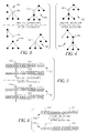
Figure 3 illustrates a genetic crossover operation for trees 80 and 82.
For the crossover operation, random nodes 88, 90 are selected for each parent and the
sub-tree from these chosen nodes are swapped. This results in the 'after crossover'
trees 84 and 86, and the illustration demonstrates the change that occurs. Similarly,
Fig. 4 illustrates a genetic mutation operation for tree 92. Nodes from the tree 96 and
98 are randomly chosen, then swapped. Tree 94 illustrates the change from tree 92
when this swap occurs.
Figure 5 and Fig. 6 illustrate similar genetic crossover and mutation
operators, but in the case of an array type data structure. In Fig. 5, for a crossover, a
position 101 within the array 100 is randomly selected and the array values 104 and
106 after the chosen position 101 are swapped between the two parents, resulting in
crossover array 102. Similarly, in Fig. 6, two random array elements 112 and 114 are
selected within a single parent 108 and their respective positions are swapped to
produce resultant array 110.
An impetus to using genetic algorithms for page layout came from an
application for creating artistic textures. This source was Karl Sims who uses genetic
algorithms for creating 2D textures as articulated in the reference; Karl Sims,
"Artificial Evolution for Computer Graphics", Proceedings of SIGGRAPH '91, pp
319-328, the contents of which are hereby incorporated by reference thereto. The
motivations behind his work was mostly artistic whereby the artist directly
determined the fitness of each solution by visual inspection. The system allowed for
random exploration of the texture space with solutions converging based on the likes
and dislikes of the artist.
Page layout has also been found to be more of an artistic task rather
than a mechanical one. Genetic algorithms are appropriate for such artistic tasks
since, unlike other more brute force algorithms, the genetic algorithm does not
attempt to mimic or model any particular process by which solutions are created.
Instead, solutions are generated randomly and are evaluated after the fact. This is
analogous to the way creative scrapbookers approach the layout problem. While
scrapbookers can't usually explain the process by which they generated their page
layouts, they certainly know a good layout when they see one.
The layout problem has a multidimensional problem space.
Considering the image distribution task discussed herein before, there are at least four
parameters that must determined for each image that is to be positioned on a page.
These are the 'x' and 'y' positions, the rotation angle of each image, and the size
scaling of each image. Multiplying that by the number of images to be placed results
in a solution space ranging from four dimensions, in the case of a single image to be
placed, to as high as forty dimensions, in the case often images to be placed. Genetic
algorithms have been proven successful for problems with similarly large dimensional
solution spaces, hence they are suitable for automatic albuming system applications.
Figure 7 illustrates the overall architecture of a page layout system 124
according to an illustrative embodiment of the present invention. The system 124
takes as input a collection of images, which are clustered by events 116, 118, 120,
122 that are to be placed in an album. Being designed to work within the framework
of an AAS, the system 124 receives the images that are sorted by event, duplicates
and duds have been removed from the collection, and that each image has been
assigned an emphasis value indicating the visual appeal of the image. The system
produces a series of album pages 140, 142, 144, 146. There are two main system
modules corresponding to the tasks outlined above. The Page Creator Module 126 is
responsible for assigning each image to an album page. The page groupings created
by this module are passed to the Image Placement Module 132, which positions the
images on each individual page. Page layouts are specified in a textual form using an
Extensible Markup Language (XML) format. Details about this format are available
from: World Wide Web Consortium, Extensible Markup Language (XML) 1.0,
http://www.w3.org/xml, February 1998, the contents of which are hereby incorporated by
reference thereto. These textual descriptions are interpreted by a XML compiler 138
that creates composite images corresponding to each completed album page. Both the
Page Creator Module 126 and Image Placement Module 132 make use genetic
algorithms and consists of their own separate genetic engines, 128 and 136
respectively. More particularly, the Page Creator Module 126 comprises a genetic
engine 128 and a page evaluation module 130, both of which are implemented in
software on a processor as is understood by those of ordinary skill in the art. The
Image Placement Module 132 comprises its own genetic engine 136 and a layout
evaluation module 134, also implemented in software. In an illustrative embodiment,
the present invention is implemented using Visual C++ 6.0 running under Windows
95/98/NT. Although porting to other platforms is readily feasible, as well as
implementation in other programming languages and operation on other platforms,
understood by those of ordinary skill in the art.
The most important implementation task involves the definition of the
fitness function. In defining the fitness for page layout, an approach whereby the
fitness is determined directly by the user's visual evaluation would be desirable since
the user's subjective interpretation would naturally fit the user's expectations of
artistic qualities. The AAS, however, is not principally designed for this type of
interaction, as one of the goals of the AAS is to minimize the user input once the
images to be placed in the album have been input to the system. This does not,
however, limit the application of the present invention page layout system in a more
interactive environment.
Due to the subjective nature of album evaluation, some indication of
the kind of layouts to be produced is required. Page layout is one of the major tasks
of those skilled in the art of graphic design. In defining a means for a user to specify
album layout preference, the present invention may rely on the principles of graphic
design. Upon surveying a number of graphic design texts, including:
Amy Arntson,
Graphic Design Basics, 3rd Ed., Harcourt Brace College Publishers, Fort Worth,
1998; Bryan L. Peterson, Using Design Basics To Get Creative Results, Northern
Lights Books, Cincinnati, OH, 1997, and
Lori Siebert and Lisa Ballard, Making a
Good Layout, Northern Light Books, Cincinnati, OH, 1992, the contents of which are
hereby incorporated by reference thereto, the preferred embodiment of the present
invention extracted a number commonly mentioned principles used in evaluation of
layout design, which include:
Each of the Page Creator Module 126 and Image Placement Module
132 judge the fitness of solutions based on a number of different criteria from the
categories listed above. The user's preference for each criterion are input to each of
the modules, as was noted respecting the AAS system diagram in Fig. 1, where user
preferences 12 are input to a user database 20 and subsequently decoded and input to
these modules. Generally, these are called value preference parameters. In the scope
of the AAS, these preference parameter values can be obtained directly by asking the
user when the pictures input for album processing. Once established, these
preferences are stored as part of a user profile and extracted whenever a particular
user requests an album be made.
In addition to preference parameters, the Page Creator Module 126 and
Image Placement Module 132 also utilize a set of importance parameters. These
importance parameters define how important it is that the system, for a given
criterion, obtains a solution where the layout produced evaluates to the exact value of
the preference parameter for that criterion. Another way of looking at this is that the
importance parameters indicate how much variation the system is allowed with
respect to a given criterion. For example, one of the evaluation criteria for the Image
Placement Module is white space. A preference of 1.0 indicates that a layout with a
larger amount of white space is desired, whereas a preference of 0.0 is indicates that a
layout with very little white space is preferred. Setting the preference for white space
to be 0.0 with an importance of 1.0, the system will do everything it can to assure that
the layout has as little white space as possible. Note that this is not the same as
saying that the importance of white space is 0.0. In the above example, white space is
very important, it's just that the user wants very little of it. An importance of 0.0
indicates to the system that it should not even pay attention to the white space
preference and, as a result produce a solution with as much or little white space as the
system deems appropriate.
Each module has a number of system parameters. These parameters
are not directly used during the layout evaluation process. Instead, these parameters
provide flexibility for the modules ensuring that they can be used by different
albuming systems and in a variety of albuming situations. Examples of system
parameters include page dimensions, resolution of the output device, minimum and
maximum number of pages per album, etc.
The function of the Page Creator Module is to place each image onto
an album page. Alternately, this module can be thought of as being responsible for
assigning to each image a page number, where this number corresponds to the page
on which the image will be placed. The Page Creator Module makes use of a number
of system parameters. These parameters are listed in Table 1 below. As noted above,
the values for these system parameters are set before the task of page creation
commences. The symbol assigned to each parameter will be used in subsequent
sections for referencing the values of these parameters.
| System parameters for Page Creator Module |
| Parameter | Symbol | Description |
| Emphasis range | σemphasis | Determines the range of "acceptable" emphasis values for the sum of the emphasis values placed on a given page |
| Minimum Pages | PAGEmin | The minimum number of pages allowable in the album |
| Maximum Pages | PAGEmax | The maximum number of pages allowable in the album |
| Penalty factor for balance | pbalance | A scale factor for penalizing unbalanced solutions |
The genome for the page creator module makes use of a tree structure as
illustrated in Fig. 8. The root of the tree, node 148, represents the entire photo album.
Interior nodes, 150, 152, 154, 156, 158, 160, 162, and 164 represent a
structure of hierarchical visual groupings of images, which, in turn, are represented
by the leaf nodes 166. However, it is equally suitable to replace this tree based
encoding with a simpler data structure based on arrays. The first layer of the tree 148
indicates the partitioning of the album into pages. Nodes below the first layer
represent visual groupings within pages 150, 152, 154, 156. The notion of this
hierarchical visual grouping is illustrated in Fig. 9, which shows the encoding of an
album with two pages and a possible layout solution that maintains the visual
grouping relationships. The album is represented by node 168. It comprises two
pages 170 and a72. Page One has three images 180. Page Two 172 has three
subgroups of images 174, 176, and 178. Each of these subgroups has two images.
Subgroup 174 having images 182, subgroup 176 having images 184, and subgroup
187 having images 186.
Standard crossover and mutation operators for tree structures are used
by the Page Creator Module. These operators are illustrated in Fig. 3 and Fig. 4, as
discussed above. Note that the crossover operator may result in a solution that
contains images appearing in multiple places within the tree or in solutions where
particular images are omitted. These types of offspring are unacceptable and will be
assigned a score of 0.0 during evaluation. Because of this, it is to be understood that
the probability of performing a crossover has been lowered thus favoring mutation
over crossover when constructing the individuals of future generations.
The determination of fitness used by the Page Creator Module is a
combination of a number of factors. First, a solution is evaluated and scored using a
number of different criteria. For each criterion, the score achieved by the solution is
compared to the preference of the user as defined by the preference parameters
supplied to the module. This comparison results in a score indicating the suitability
of the solution given the preferences of the user. Finally, the final fitness is obtained
by scaling these suitability values on a criterion by criteria basis using the importance
parameters, also supplied by the user.
In the following paragraphs, the fitness evaluation process is discussed
in more detail. First a discussion of the evaluation criteria and judging procedure is
given. Then the means by which the final fitness is obtained is discussed.
Evaluation Criteria - Solutions for the Page Creator Module are
evaluated on the following four criteria:
- Balance - an evaluation of the balance of the image distribution with respect
to the number of images on each page.
- Emphasis - an evaluation of whether image emphasis values are equally
distributed amongst album pages.
- Chronology - an evaluation of how well the distribution of images on
sequential pages matches the chronology of the images.
- Unity - an evaluation of whether images belonging to the same event and/or
sub-event are grouped on the same or subsequent pages.
For each criterion, a score ranging from 0.0 to 1.0 is given to each
solution based on the evaluation. Details of the evaluation method for each criterion
are given below.
Note that solutions containing a total number of pages outside the
range determined by the system parameters PAGEmin - PAGEmax, are deemed as unfit
solutions and given a final fitness of 0.0. Similarly, solutions that place a single
image in multiple places, or solutions that do not consider all images are immediately
assigned a fitness of 0.0.
Evaluation of Balance - The balance score is a measure of whether there are
an equal number of images on each page. A solution with an equal number of images
on all of its pages will obtain a perfect score of 1.0. The score is determined by, first,
calculating the mean number of images per page. The average deviation from this
mean amongst all the pages in the album is determined and scaled by a penalty factor
(pbalance). Since a perfect score will have a deviation of 0.0, the final score is obtained
by subtracting this scaled deviation value from 1.0.
Evaluation of Emphasis - In considering emphasis, the evaluation
method attempts to judge how equally distributed the emphasis is amongst the pages
in the album. It is undesirable to have too much emphasis on a single page since this
will limit the capability of the image placement module to adequately emphasize the
images that have high emphasis values. At the same time, a page with too little
emphasis on a page will force the image placement module to emphasize images that
don't properly deserve emphasis.
In the evaluation of emphasis, it is assumed that the sum of the
emphasis values for all of the images on a "perfect" page will equal 1.0. This ideal
value of 1.0 could be replaced by some value based on the average of the emphasis
values amongst all of the images. An evaluation score for emphasis is obtained by
calculating the percentage of pages whose emphasis sum amongst all of the images
placed on it, are within an "acceptable" range. This "acceptable range" is defined to
be 1.0 ± σemphasis.
Evaluation of Chronology - In evaluating chronology, each solution is
judged based on how closely the order of the images as presented on the pages match
that of the chronology of the images. To perform this evaluation, first define the
notion of a "chronology range". This range is defined as the range of chronology
values for images that should appear on the page if the album was perfectly ordered
in time. For example, given an album with three pages, with two images on the first
page, four images on the second page, and three images on the final page, the
chronology range for each page would be given according to Table 2:
| Chronology ranges |
| Page | Chronology range |
| Page 1 | 1-2 |
| Page 2 | 3-6 |
| Page 3 | 7-9 |
When performing the evaluation for chronology, each page is given a
score based on the percentage of images that fall within chronology range for the
page. The final score is obtained by computing the average of the page scores over
all of the pages in the album.
Evaluation of Unity - Evaluation of unity is performed by considering
the images belonging to events and sub-events and their proximity to each other when
constructing the pages for the album. Two types of scores are computed when
evaluating unity:
The above scores can be calculated on an event and/or sub-event basis.
The system allows one to define whether sub-event checking should be performed.
The final unity score is a linear combination of scores for page and event unity for
each evaluation performed. Individual scores are scaled equally in determination of
the final unity score.
Calculation of Final Fitness - The evaluation algorithms listed above
provide raw scores for each one of the evaluation criteria. In determining the final
fitness of the solution, both the preferences and the importance of each criteria, as
specified by the preference and importance parameters supplied by the user, must also
be considered. To determine how well a solution meets the preferences of the user,
the difference between the user preference and the raw score is calculated for each
criterion. These differences are subtracted from 1.0 resulting in a fitness score for
each criteria such that a fitness score of 1.0 indicates a good match with user
preferences and a score of 0.0 indicated a bad match with user preferences.
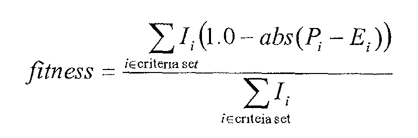
The values of the importance parameters are used to scale the
contribution of each criterion to the final fitness score. Given a set of importance
parameter values, the best possible score obtainable for a given run of the algorithm
can be calculated by assuming the fitness score for each criterion to be perfect (i.e.
equal to 1.0). The final fitness score is determined by scaling each of the actual
fitness scores for each criteria by the corresponding importance parameter value,
summing the results from all of the criteria and dividing this sum by the best possible
fitness value obtainable. This final fitness score can be summarized mathematically
as:
where 'I' represents the set of importance parameters value (1 per criteria), 'P'
represents the set of preference parameter values (1 per criteria) and 'E' represents the
set of raw evaluations scores as determined by the procedures outlined above (1 per
criteria).
To illustrate the relationship of these functions and clarify the process
generally, what follows are several examples of using the Page Creator Module on a
group of images. In each of the examples, the image set presented in Fig. 10 is used.
While the images themselves are not present, the data is derived from actual user
images and represents a typical user role of film consisting of 40 images taken from a
variety of different events. To facilitate viewing the effects of the various evaluation
criteria, the images have been labeled with a chronology index (C), giving the relative
ordering of the picture with respect to the entire set. An assigned emphasis value (E)
is also supplied with each image. Thus, referring to Fig. 10, groups of images from
six events are illustrated. Event One 188 includes twelve imaged, chronologically
C:0 through C:11. Event two 190 includes nine images, chronologically C:12
through C:20. Event three includes eight images, chronologically C:21 through C:28.
Event four 194 includes six images, chronologically C:29 through C:34. Event five
196 includes four images, chronologically C:35 through C:38. Finally, event six 198
includes one image, chronologically C:39. Each image has a emphasis value which
can be determined by reference to Fig. 10.
In each of tests illustrated in Fig. 11 through Fig. 16, the effects due to
a single criterion are illustrated. In these tests, the preference and importance
parameters for the criterion in question are set to 1.0 and the importance parameters
for all other criteria is set to 0.0. In each test, the genetic algorithm is run for 10,000
generations, producing solutions with scores ranging from 0.75 through 1.0.
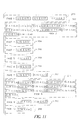
Figure 11 illustrates the effect of chronology. A good chronology
score is generally not difficult to achieve given that the images are originally
presented in chronological order. In fact, the trivial solution is a layout of six pages,
where each page contains the images from a single event. In Fig. 11, PAGEmin is set
to ten as to assure that the Page Creator Module performs some non-trivial work (e.g.,
it cannot find the trivial solution as six pages is prohibited by this parameter). In the
figure, the chronology index is displayed on each image. Referring to Fig. 11, it can
be seen that ten pages are output from the Page Creation Module, identified by
reference numbers 200, 202, 204, 206, 208, 210, 212, 214, 216, and 218,
respectively. Each page has one or more images assigned to it, and the images are in
chronological order, as would be expected.
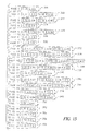
Figure 12 illustrates the effects of unity Since unity forces images of the same
event to be placed next to each other, as with the chronology case, the trivial solution
of a six page album with one event per page will receive a perfect score of one. For
the test illustrated in Fig. 12, PAGEmin is set to 10, once again, to allow the module to
perform some non-trivial work. This particular example, though not perfect, tends to
keep events together, if not on the same page, on subsequent pages. The output
comprised 16 pages. Page 1, 220, has a single image from event six. Page 2, 3, 4,
and 5, reference numerals 222, 224, 226, and 228 respectively, have single images
from event two. Page 6, 230, has two images from event five. Pages 7 and 8, 232
and 234, have single images from event five. Page 9, 236, has three images from
event three. Pages 10, 11, and 12, reference numerals 238, 240, and 242 respectively,
have single images from event three. Page 13, 244 has three images from event one.
Page 14, 246, has two images from event one. Page 15, 248, has seven images from
event one, five images from event 2, two images from event 4, and five images from
event four. In this page, all common event images are adjacent to one another.
Finally, page 16, 250, has a single image from event 4. This solution received a score
of 0.8.
The effects of balance are illustrated in Fig. 13. In this example, no
constraints are placed on the minimum or maximum number of pages. Note that
pages 2, 4, 5, 6, 7, 9, 13, 16, and 17, identified by reference numerals 254, 258, 260,
262, 264, 268, 276, 282, and 284 respectively, all comprise two images. Pages 3, 8,
10, 11, 12, 14, and 15, identified by reference numerals 256, 266, 270, 272, 274, 278,
and 280 respectively, each comprise three images. Page 1, 252 comprises a single
image. Thus, a degree a balance is achieved, but without exacting uniformity.
The effects of emphasis are illustrated in Fig. 14. As with the balance
test, no constraints were placed on the minimum or maximum number of pages. Note
that emphasis values are printed for each image, along with the chronology value.
Seventeen pages were generated, identified by reference numerals 284, 286, 288, 290,
292, 294, 296, 298, 300, 302, 304, 306, 308, 310, 312, 314, and 316. Note that
images with high emphasis values tend to be placed alone on their own page. Also
note that image with lower emphasis values are combined with other similar images
onto a single page.
Considering the solutions above, it is clear that unity and chronology tend to
lump images together on the same page, whereas emphasis and balance tend to favor
solutions where images are more spread out amongst pages. An interesting
compromise is reached when combining the effects of two criteria. In Fig. 15, equal
importance values are assigned to emphasis and unity (with the importance of balance
and chronology set to 0.0). Twenty-one pages, identified by reference numerals 318,
320, 322, 324, 326, 328, 330, 332, 334, 336, 338, 340, 342, 344, 346, 348, 350, 352,
354, 356, and 358, were generated with the image arrangement presented in the
drawing figure. This particular solution earned a score 0.81. Note that images
belonging to the same event tend to remain together. At the same time, the
introduction of emphasis eliminates the tendency to combine a large number of
images onto one page (as is evident by reference to Page 15 in Fig. 12). This same
observation is also evident in Fig. 16 where balance and chronology are assigned
equal importance (with the importance of unity and emphasis set to 0.0). In this case,
some sense of unity is achieved indirectly since events are presented in chronological
order. Note in Fig. 16 that thirteen pages are generated, identified by reference
numerals 362, 364, 366, 368, 370, 372, 374, 376, 378, 380, 382, 384, and 386.
Now considering the Image Placement Module (item 134 in Fig. 7), its
role is to position images on individual album pages once the Page Creator Module
has assigned images to particular pages, as discussed above. Given a set of 'N'
images to be placed on an individual album page, this module will determine, for
each image, the following positioning parameters:
- 'x' position - The x coordinate of the center of the image.
- 'y' position - The y coordinate of the center of the image.
- 's' Scale Factor - The amount of scaling to be applied to the image. Note that
the aspect ratios of the images are preserved. Thus, equal scaling is performed
in both the horizontal and vertical directions.
- '' Rotation - Amount of rotation about the center vertical axis of the image.
In the following discussions, the positioning parameters (x, y, s, ) are
be used to indicate the calculated position of an image on the page with each member
of the four factors corresponding to a respective value listed above. A set of four
positioning parameters define, and are referred to as, the image position.
In performing the solution encoding and solution fitness evaluation,
the Image Placement Module makes use of a number of system parameters. The
values of these parameters will vary dependent on the application using the module
and are set before layouts are processed by the module. A list of these system
parameters is given in Table 3. The symbol assigned to each parameter will be used
for reference hereinafter.
| System parameters for Image Placement Module |
| Parameter | Symbol | Description |
| Album Page Width | Wpage | The width of the album page in pixel units (or physical units). |
| Album Page Height | Hpage | The height of the album page in pixel units (or physical units). |
| Maximum Rotation | max | Maximum allowable rotation about the center vertical axis of an image. |
| Minimum Scaling | smin | Minimum allowable scale factor that can be applied to an image. |
| Maximum Scaling | smax | Maximum allowable scale factor that can be applied to an image. |
| Minimum white space | WSmin | Minimum allowable amount of white space on the page, expressed as a percentage of the total page area. |
| Maximum white space | WSmax | Maximum allowable amount of white space on the page, expressed as a percentage of the total page area. |
| Minimum overlap | OLmin | Minimum allowable amount of overlap, expressed as a percentage of image area. |
| Maximum overlap | OLmax | Maximum allowable amount of overlap, expressed as a percentage of image area. |
| Border deviation | BDRmax | Maximum deviation allowed in definition of a natural border created by the image placements. |
| Rotation standard deviation | σ | Standard deviation used in Gaussian scaling of rotation. |
A floating point array is used as the genome for the image placement
module. Reference is directed to Fig. 17, which is an illustration of such an array 388
in an illustrative embodiment of the present invention. Each element of the array
corresponds to an individual positioning parameter. The first four elements, 394, 396,
398, and 400 specify the Position (x), Position (y), Scaling (s), and Rotation () for
the first image 390. Each image is similarly defined through the Nth image 392. The
complete genome is comprised of the image positions of all images to be placed.
Thus, for a page with N images, the length of the genome is four times N.
All elements of the array are floating point values ranging from 0.0 to
1.0. This is to assure that all genes (i.e. array elements) are considered equal when
performing genetic operations. The value of the genes for a given image are be
referred as genex, geney, genes, and gene for the value corresponding to the x
position, y position, scaling, and rotation respectively. The mappings from these
array element values to positioning parameter values for each positioning parameter
are given hereinafter.
The x and y positioning parameters give the placement of the center of
a given image on the album page. In the genome, this is expressed relative to the
total height and width of the page with the origin being the upper-left corner of the
page. Appropriate calculations are made by the Image Placement Module to assure
that an image placement calculated from given gene values will not result in any part
of the image being placed off the boundaries of the album page. The mapping from
the gene values for x and y positioning to actual x and y position on the page can thus
be given by:
x = Wimage 2 + (genex · (Wpage - Wimage ))
y = Himage 2 + (geney · (Hpage - Himage ))
where the width and height of the image in pixels are given by Wimage and
Himage respectively.
Scaling is expressed in the gene by a linear ramp between the
minimum allowable scaling and the maximum allowable scaling. The mapping from
gene value to actual scale factor is thus given by:
s = s min + (genes · (s max - s min))
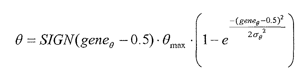
The rotation positional parameter gives the rotation of an image about
the center of the image with respect to the vertical axis of that image. Reference is
directed to Fig. 18. An image 402 may be rotated to a counter-clockwise position 406
or a clockwise position 404. Rotation is encoded in the gene by a Gaussian scaling
between maximum allowable rotation in the negative (counter-clockwise) direction
through angle 408 and the maximum allowable rotation in the positive (clockwise)
direction through angle 410. Thus, the vertical axis of the image 412, is rotated
through the aforementioned angles to a position 414, or 416. A Gaussian scaling is
used as opposed to linear scaling to control the amount of image rotation; favoring
small rotations over large amounts of rotation.
The mapping from gene value to actual rotation angle can thus be
given by:
where SIGN (x) equals 1 if x is positive, -1 if x is negative and 0 otherwise.
In an illustrative embodiment, standard crossover and mutation
operators for arrays are used by the Image Placement Module. These operators are
illustrated in Fig. 5 and Fig. 6. In additional, a value mutation operator is defined and
also used alternately by the module. This value mutation operator will choose a
random gene within the array and deviate it's value by a random amount. Care is
taken to assure that the gene value remains between 0.0 and 1.0 after the mutation.
Similar to the Page Creator Module, the fitness for the Image
Placement Module is a combination of raw evaluations in a number of given criteria
considered with respect to the preference and importance parameters supplied from
the user preference database. The method for evaluation of fitness is outlined in the
following discussion. The evaluation criteria for layout solutions include seven
different criteria. These criteria can be categorized as follows.
- Spatial Criteria
- White space - an evaluation of the amount of white space on the page.
- Overlap - an evaluation of the amount of image overlap on a page.
- Rotation - an evaluation of the amount of image rotation on a page.
- Balance Criteria
- Spatial Balance - an evaluation of how equally distributed the images are
on the page.
- Rotational Balance - an evaluation of how equally balanced the rotation of
images are.
- Border Symmetry - an evaluation of how well the edges of the images on
the page form a natural border.
- Emphasis - an evaluation of how well the scaling of images relate to image
emphasis values.
For each criterion, a solution, represented by a genome, is given a score
ranging from 0.0 to 1.0. In order to perform the evaluations, a mockup of the page
layout is generated by decoding the genome values and positioning rectangles on a
two-dimensional grid using a polygon-clipping library. In an illustrative embodiment
of the present invention, the generic polygon clipping library according to the
reference: Alan Murta, "A Generic Polygon Clipping Library", Department of
Computer Science, University of Manchester, 1999, the contents of which are hereby
incorporated by reference thereto, is used. This mock layout is used to calculate the
various area calculations used in the evaluations.
The evaluation of white space involves a score of the white space,
which is a measure of the amount of white space on the page and is determined by
calculating the percentage of the page area not filled by any images. A score of 0.0
indicates a layout where the images placed on the page take up the entire page area.
A score of 1.0 is indicative of an empty page with no images on it (i.e. the entire page
is white space). As indicated in Table 3, there are system parameters that limit the
acceptable amount of white space allowed. Solutions that result in white space
percentages below the minimum or greater than the maximum are tagged as
unacceptable solutions and given a final fitness value of 0.0.
In evaluating overlap, the maximum overlap between any two images
is considered. The overlap score is defined as the maximum percentage of any image
area covered by another image over all of the images placed on the page. Similar to
white space, there are system parameters that limit the acceptable amount of overlap
allowed. See Table 3, above. Solutions that result in overlap scores below the
minimum or greater than the maximum are tagged as unacceptable solutions and
given a final fitness value of 0.0.
The rotation score is an indication of the total amount of image
rotation on an album page. It is derived by averaging the absolute values of the
image rotations over all of the images. This average is scaled by max to achieve a
score between 0.0 and 1.0. Note that since the interpretation of the genome encoding
for rotation ensures that the rotation for each image will be between -max and +max,
this rotation evaluation score will never exceed 1.0.
Spatial balance is evaluated by comparing the image areas in the four
quadrants of the album page. The page is first split horizontally into equal halves.
The amount of page area containing images for both halves are determined and the
ratio of the half with the smaller image area over the half with the larger image area is
calculated. For a spatially balanced layout, this ratio will be close to 1.0. The same
procedure is performed in the vertical direction. The final spatial balance score is the
average of the two ratios.
The score for rotational balance is calculated in a manner similar to
that of rotation. Like with the rotation evaluation, the rotation balance values over all
the images are averaged. However, unlike the evaluation for rotation, the actual
rotation values and not the absolute values of these rotations are considered when
calculating the average. The rational behind this evaluation is that for a rotationally
balanced layout, the summation of all the rotations should amount to 0.0. The
rotational balance score is obtained by scaling the calculated signed average by max
and then subtracting this value from 1.0. This way, a very rotationally balanced
layout, (i.e. one where the signed average of the rotations is 0.0) will produce a score
of 1.0. Similarly, a very rotationally unbalanced layout, one where the average of the
rotations is close to max will earn a score of 0.0.
The border symmetry score evaluates how closely the edges of the
image on the page form a natural boundary. For each edge of the album page (top,
bottom, left, right), a border distance is determined by considering the image endpoint
closest to the page edge and calculating the distance from the edge to the endpoint.
The mean distance amongst the four edges is determined and the average distance
from the mean amongst the four edges is calculated. This average is scaled by
BDRmax and subtracted from 1.0 to generate the final score. Note that if the average
distance is greater than BDRmax, the solution is flagged as unfit and is assigned a final
fitness value of 0.0.
The emphasis score measures the proportionality of the size of the images
with respect to the emphasis values assigned to the images. The rationale behind this
evaluation stems from the notion that images with large emphasis values should take
up more space on the page. The comparison made during evaluation is relative to the
sizes of all of the images. For each image, the size relative to the largest image in the
group is calculated and expressed as a percentage. This percentage is then subtracted
from the emphasis value assigned to the image. Then mean difference amongst all
the images on the page is calculated and this average is subtracted from 1.0, assuring
that an emphasis score of 1.0 indicates a strong positive correlation between image
size and emphasis values.
In a fashion similar to the approach used with the Page Creator
Module, in determining the final fitness of the solution, both the preferences and the
importance of each criterion, as specified by the preference and importance
parameters supplied by the user, must also be considered. Thus, the Image Placement
Module determines final fitness in the same manner as the page creator module
described herein before. The only difference is in the set of criteria considered in
performing the evaluation. Thus, final fitness for the Image Placement Module
according to an illustrative embodiment of the present invention is described by:
where I represents the set of importance parameters value (1 per criteria), P
represents the set of preference parameter values (1 per criteria) and E represents the
set of raw evaluations scores as determined by the procedures outlined above (1 per
criteria).
To gain a better understanding of the Image Placement Module layout
functionality, it is beneficial to contemplate a series of exemplar page layouts, each of
which exercises certain aspects of this module. These layouts appear in Figs. 23
through 38. In each of the layouts, the illustrative images presented in Fig. 19
(reference numeral 418), Fig. 20 (reference numeral 420), Fig. 21 (reference numeral
422), and Fig. 22 (reference numeral 424) are supplied as input to the Image
Placement Module). Note that the values given below each image are the emphasis
values for the particular image. In the following example layouts, each criterion will
be considered separately to illustrate the effect of manipulating the preference for the
criteria in question. In each of the examples, the module ran the genetic algorithm
through three hundred generations resulting in layouts with final scores ranging from
0.85 - 0.95.
Figures 23 and 24 illustrate the effect of the white space preference.
Note that SPmax has been set to 75% and SPmin has been set to 5%. For Fig. 23, image
426, the preference is set to 0.0, and, for Fig. 24, image 428, the preference is set to
1.0.
Figure 25 and 26 illustrate the effect of overlap. In this example, the
white space preference is kept constant between the two layouts. The value of OLmin
is set to be 0% whereas the value of OLmax is set at 25%. For Fig. 25, image 430, the
preference is set to 0.0, and, for Fig. 26, image 432, the preference is set to 1.0.
The effect of rotation is illustrated in Figs. 27 and 28. Once again, the
white space preference is kept constant between the two layouts. In addition, the
overlap preference is set to 0. The value of max is set at 30 degrees. For Fig. 27,
image 434, the preference is set to 0.0, and, for Fig. 28, image 4436, the preference is
set to 1.0.
In Figs. 29 and 30, the effects of rotational balance are shown. For
sake of illustration, the rotation preference for both layouts is set to 1.0. For Fig. 29,
image 438, the preference is set to 0.0, and, for Fig. 30, image 440, the preference is
set to 1.0.
The effects of spatial balance are shown in Figs. 31 and 32. Note that
setting the preference to 0.0 results in a layout where one quadrant of the page is
completely empty where the rest have images in them. For Fig. 31, image 442, the
preference is set to 0.0, and, for Fig. 32, image 444, the preference is set to 1.0.
Figures 33 and 34 show the effects of border symmetry. In order to
emphasize the border effect, the rotation and overlap preferences in this example are
set to 0.0. For Fig. 33, image 446, the preference is set to 0.0, and, for Fig. 34, image
448, the preference is set to 1.0.
Finally, the effects of emphasis are illustrated in Figs. 35 and 36. Note
that setting the emphasis preference to 1.0 indicates that the user wants a strong
relationship between the size of the image and the emphasis value. Considering the
method by which emphasis is evaluated, described herein before, setting this
preference set to 0.0, indicates to the system that this relationship should be reversed.
This is clearly the effect shown in these Figs. considering the emphasis values listed
for the reference images from Figs. 19 through 21. For Fig. 35, image 450, the
preference is set to 0.0, and, for Fig. 36, image 4452, the preference is set to 1.0.
The variety of page layouts that can be produced by the Image
Placement Module is best illustrated when modifying several preference parameters at
once. In Figs. 37 and 38, the preferences for white space, rotation, and overlap are all
modified between the two layouts. The results are the two layouts illustrated with
two entirely different feels to them, Fig. 37, image 454, being very traditional and
rigid, Fig. 38, image 456, having more of a whimsical quality to it.
Thus, the present invention has been described herein with reference to
a particular embodiment for a particular application. Those having ordinary skill in
the art and access to the present teachings will recognize additional modifications,
applications and embodiments within the scope thereof. For example,