EP1220497A2 - Packet switch - Google Patents
Packet switch Download PDFInfo
- Publication number
- EP1220497A2 EP1220497A2 EP01119759A EP01119759A EP1220497A2 EP 1220497 A2 EP1220497 A2 EP 1220497A2 EP 01119759 A EP01119759 A EP 01119759A EP 01119759 A EP01119759 A EP 01119759A EP 1220497 A2 EP1220497 A2 EP 1220497A2
- Authority
- EP
- European Patent Office
- Prior art keywords
- scheduler
- sections
- scheduling
- packet
- section
- Prior art date
- Legal status (The legal status is an assumption and is not a legal conclusion. Google has not performed a legal analysis and makes no representation as to the accuracy of the status listed.)
- Granted
Links
Images










Classifications
-
- H—ELECTRICITY
- H04—ELECTRIC COMMUNICATION TECHNIQUE
- H04L—TRANSMISSION OF DIGITAL INFORMATION, e.g. TELEGRAPHIC COMMUNICATION
- H04L47/00—Traffic control in data switching networks
- H04L47/10—Flow control; Congestion control
- H04L47/28—Flow control; Congestion control in relation to timing considerations
-
- H—ELECTRICITY
- H04—ELECTRIC COMMUNICATION TECHNIQUE
- H04L—TRANSMISSION OF DIGITAL INFORMATION, e.g. TELEGRAPHIC COMMUNICATION
- H04L47/00—Traffic control in data switching networks
- H04L47/50—Queue scheduling
-
- H—ELECTRICITY
- H04—ELECTRIC COMMUNICATION TECHNIQUE
- H04L—TRANSMISSION OF DIGITAL INFORMATION, e.g. TELEGRAPHIC COMMUNICATION
- H04L47/00—Traffic control in data switching networks
- H04L47/50—Queue scheduling
- H04L47/52—Queue scheduling by attributing bandwidth to queues
- H04L47/521—Static queue service slot or fixed bandwidth allocation
-
- H—ELECTRICITY
- H04—ELECTRIC COMMUNICATION TECHNIQUE
- H04L—TRANSMISSION OF DIGITAL INFORMATION, e.g. TELEGRAPHIC COMMUNICATION
- H04L47/00—Traffic control in data switching networks
- H04L47/50—Queue scheduling
- H04L47/62—Queue scheduling characterised by scheduling criteria
- H04L47/622—Queue service order
- H04L47/6225—Fixed service order, e.g. Round Robin
-
- H—ELECTRICITY
- H04—ELECTRIC COMMUNICATION TECHNIQUE
- H04L—TRANSMISSION OF DIGITAL INFORMATION, e.g. TELEGRAPHIC COMMUNICATION
- H04L49/00—Packet switching elements
- H04L49/30—Peripheral units, e.g. input or output ports
- H04L49/3018—Input queuing
-
- H—ELECTRICITY
- H04—ELECTRIC COMMUNICATION TECHNIQUE
- H04L—TRANSMISSION OF DIGITAL INFORMATION, e.g. TELEGRAPHIC COMMUNICATION
- H04L49/00—Packet switching elements
- H04L49/50—Overload detection or protection within a single switching element
- H04L49/501—Overload detection
- H04L49/503—Policing
Definitions
- the present invention relates to a packet switch for outputting packets input through an input line after allocating them to a plurality of output lines.
- the probable means for realizing a node having a terabit switching capacity is an input buffer packet switch capable of performing a process at a high memory access speed.
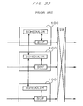
- FIGS. 22 and 23 show the distribution of the scheduling functions in the conventional input buffer packet switch.
- FIG. 22 shows the configuration of the packet switch in which the scheduling functions are distributed and fed.
- FIG. 23 shows the configuration of the packet switch in which the scheduling functions are collectively assigned.
- the input buffer packet switch in which the scheduling functions are distributed and assigned includes an interface card 100 containing an input buffer and a scheduler for each input line.
- the scheduling information can be transmitted and received (a notification of an undefined line can be given) among schedulers by interconnecting the schedulers in the adjacent interface cards 100, and the scheduling process can be performed for all input lines.
- the number of interface cards 100 can also be increased or decreased to be equal to the number of the input lines. Therefore, the input buffer packet switch with the configuration shown in FIG. 22 excels in extensibility.
- the input buffer packet switch in which the scheduling functions are collectively assigned includes a scheduling function section for all input lines collectively in one scheduler card 110, thereby performing a scheduling process on all input lines. Since the length of the wiring between the scheduling function sections is short, the wiring reduces a delay, and the restrictions placed by the delay time of a signal when the switch is installed can be considerably reduced.
- the scheduler card 110 In the conventional input buffer packet switch in which the scheduling function sections are collectively assigned, it is necessary for the scheduler card 110 to be provided with the largest possible number of scheduling function sections even when there are a small number of the input lines actually. After installing the scheduling function sections, the number of the sections is fixed. Therefore, this switch is wasteful and poor in extensibility.
- the present invention has been achieved to solve the above mentioned problems, and aims at providing a packet switch which has less restrictions when it is installed, and can reduce a wasteful configuration, and excels in extensibility.
- the packet switch according to the present invention includes N input buffer sections and ⁇ scheduler sections, and switch section.
- the N input buffer sections are provided respectively for N input lines, and store packets input through the corresponding input lines.
- the ⁇ scheduler sections independently perform respective scheduling processes, and each section determines an output line among the M output lines to which the packet stored in each of the N input buffer sections is transmitted.
- a switch section outputs the packet output from each of the N input buffer sections to the output line determined by the scheduler sections.
- the above mentioned N input buffer sections cyclically use the results of the scheduling processes performed by the ⁇ scheduler sections. Since the plurality of scheduler sections independently perform the scheduling processes, it is not necessary to control the conflict among the scheduler sections, etc., thereby causing no problem of signal delays, etc. and considerably reducing the restrictions when the switch is installed. Furthermore, since only the scheduler sections of the necessary number are to be provided, a wasteful configuration can be avoided. Additionally, since the scheduler sections can be added later, an extensible packet switch can be realized.
- the scheduling process is performed by the above mentioned scheduler section in response to the scheduling request notification transmitted from the N input buffer sections. It is desired that each of the N input buffer sections distributes the scheduling request notification to a different scheduler section. By distributing the scheduling request notification to a different scheduler section, the loads of the processes can be equally distributed among the scheduler sections.
- the above mentioned input buffer sections have M queues storing the packets to be transmitted to the M output lines. It is desired that the scheduling request notification is cyclically transmitted to the scheduler sections for each of the M queues. By transmitting the scheduling request notification cyclically to the scheduler sections for each of the M queues, the scheduling request notification can be distributed equally among the scheduler sections.
- the above mentioned input buffer section transmits the scheduling request notification cyclically to the scheduler sections for each input line.
- the scheduling request notification can be distributed equally among the scheduler sections.
- the above mentioned input buffer section transmits the scheduling request notification cyclically to the scheduler sections for each unit time.
- the scheduling request notification can be distributed equally among the scheduler sections.
- the above mentioned input buffer section checks the number of unprocessed scheduling request notifications for each of the ⁇ scheduler sections such that the next scheduling request notification can be transmitted to the scheduler section of the smallest number.
- the scheduling request notifications can be distributed equally among the scheduler sections.
- the above mentioned input buffer section manages the number of scheduling request notifications transmitted to each of the a scheduler sections such that the operation of transmitting a scheduling request notification to the scheduler section having the number equal to or larger than a predetermined number of scheduling request notifications can be delayed until the number becomes smaller than the predetermined number.
- the number ⁇ of the scheduler sections is set to a value equal to or larger than a multiple L.
- the scheduling process can be performed without delay as the entire ⁇ scheduler sections.
- L - ⁇ is equal to or larger than 1 (that is, there are L or more schedulers), and N input buffer sections cyclically use the results of the scheduling processes of all of ⁇ scheduler sections.
- ⁇ - L scheduler sections are used as a redundant system so that, when the scheduler sections other than the redundant system become faulty, the scheduler sections in the redundant system can replace the faulty sections.
- each of the number ⁇ of the scheduler sections and the time required for the scheduling process variable depending on the number N of input lines and the number M of output lines.
- the number of scheduler sections and the processing time are set to small values.
- the number of scheduler sections and the processing time are set to large values.
- scheduler sections perform the scheduling process using lines including unused lines so that a plurality of results of scheduling processes can be obtained from one scheduling process by switching lines between the unused lines and the actually used input and output lines.
- the number of lines can be changed without changing the number of scheduler sections or the processing time, thereby realizing an extensible packet switch.
- FIG. 1 shows a configuration of the packet switch according to an embodiment of the present invention.
- a packet switch 100 according to an embodiment of the present invention comprises a switch section (SW) 10, N input buffer sections 20, and ⁇ scheduler sections 30.
- the switch section 10 outputs a packet input through one of the N input lines to one of the M output lines.
- the switch section 10 includes no buffer, and cannot store a packet.
- Each of the N input buffer sections 20 is provided respectively corresponding to each of the N input lines accommodated in the switch section 10.
- Each of the input buffer sections 20 is provided with M logic queues VOQ (Virtual Output Queue) corresponding to the M output lines accommodated by the switch section 10, accumulates a received packet input through a one-to-one corresponding input line in the logic queue VOQ corresponding to the destination output line, and reads the leading packet in the logic queue VOQ specified by a grant notification which indicates the permission to output a packet, and is transmitted from any of the scheduler sections 30.
- VOQ Virtual Output Queue
- Each of the ⁇ scheduler sections 30 performs a scheduling process to determine a destination output line of a packet input through each input line.
- the load of the process performed by each scheduler section 30 can be reduced.
- the scheduling processes performed by the plurality of scheduler sections 30 are referred to as a load-distributed scheduling process.
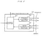
- FIG. 2 shows a detailed configuration of the input buffer section 20.
- the input buffer section 20 comprises a packet buffer 22 including the above mentioned M logic queues VOQ, a request allotment section 24, and a read instruction section 26.
- the request allotment section 24 distributes request notifications which are the scheduling request notifications corresponding to the packets accumulated in each logic queue VOQ in the packet buffer 22 equally to the ⁇ scheduler sections 30.
- the read instruction section 26 issues a read instruction to the logic queue VOQ in the packet buffer 22 whose packet transmission timing is reached based on the contents of the grant notifications transmitted from the ⁇ scheduler sections 30.
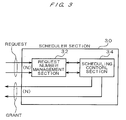
- FIG. 3 shows a detailed configuration of the scheduler section 30.
- the scheduler section 30 comprises a request number management section 32 and a scheduling control section 34.
- the request number management section 32 increments the number of requests corresponding to the combination of an input line and a logic queue VOQ when a request notification corresponding to the combination is received, and decrements the number of requests when the scheduling process is specified.
- the scheduling control section 34 determines the destination output lines of the packet to be output at a timing T from each input line according to a predetermined algorithm. Practically, the scheduling control section 34 selects one of the output lines having the number of requests counted by the request number management section 32 equal to or larger than 1 for each input line.
- each scheduler section 30 can perform the scheduling process taking its time ⁇ times as long as the time taken by the scheduling process performed by one scheduler section. For example, assuming that the time required to transmit a packet input through each input line to a corresponding output line is 'one packet hour' , each scheduler section 30 can perform within ⁇ packet hours the scheduling process of determining a destination output line of a packet input through each of the N input lines.
- the packet switch 100 has the above mentioned configuration. Described below is the scheduling process of the packet switch.
- each scheduler section 30 performs a scheduling process depending on whether or not there is a request notification addressed to itself.
- the scheduling algorithm can adopt various conventional methods. Described below is the operation of selecting a logic queue VOQ for each output line in the round-robin scheduling.
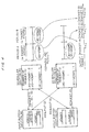
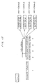
- FIG. 4 shows a practical example of a load-distributed scheduling process.
- FIG. 4 shows a practical example of a scheduling process in which the number ⁇ of the input lines, the output lines, and the scheduler sections 30 is 2 for simple explanation.
- two input lines, two output lines and the logic queues VOQ corresponding to each of the output lines are assigned the serial numbers of #0 and #1 for identification.
- One of the two scheduler sections 30 is referred to as a scheduler #0 (SCH#0), and the other as a scheduler #1 (SCH#1).
- one of the two input buffer sections 20 corresponding to the input lines #0 and #1 is referred to as an input buffer section #0, and the other as an input buffer section #1.
- Each configuration included in them are assigned either #0 or #1 after each name for identification of a corresponding input line.
- One input buffer section #0 sequentially receives four packets (1), (2), (3), and (4) through an input line #0.
- the first, second, and third packets (1), (2), and (3) are assigned the destination output line #0
- only the fourth packet (4) is assigned the output line #1. Therefore, the packet buffer #0 in the input buffer section #0 stores the first, second, and third packets (1), (2), and (3) in the logic queue VOQ #0, and the fourth packet (4) in the logic queue VOQ #1.
- the request allotment section #0 transmits a request notification to one scheduler section #0 upon receipt of the first, third, and fourth packets (1), (3), and (4), and transmits a request notification to the other scheduler section #1 upon receipt of the second packet (2).
- the request notification includes an input line number, an output line number (number of a logic queue VOQ), 'enable', etc.
- the other input buffer section #1 sequentially receives the fifth and sixth packets (5) and (6) through the input line #1. These two packets (5) and (6) are assigned the destination output line #1. Therefore, the packet buffer #1 in the input buffer section #1 stores these fifth and sixth packets (5) and (6) in the logic queue VOQ #1.
- the request allotment section #1 transmits a request notification to one scheduler section #0 upon receipt of the fifth packet (5), and transmits a request notification to the other scheduler section #1 upon receipt of the sixth packet (6).
- the scheduler sections #0 and #1 independently operate, and manage the number of received request notifications for each logic queue VOQ by the included request management sections #0 and #1.
- the scheduler sections #0 and #1 perform load-distributed scheduling processes described below depending on the number of the requests managed by the request management sections #0 and #1. It is assumed that the scheduling processes performed by the round-robin scheduling system are performed in the order of the input line #1 and the input line #0.
- the scheduling control section #1 in the scheduler section #1 first determines whether or not there is a request notification about all logic queues VOQ corresponding to the input line #1, and selects by the round-robin scheduling system one of the logic queues VOQ which has received a request notification but has not been assigned the destination of a packet.
- the round-robin scheduling system selects by the round-robin scheduling system one of the logic queues VOQ which has received a request notification but has not been assigned the destination of a packet.
- only a request notification corresponding to the logic queue VOQ #1 is issued relating to the input line #1 (i#1). However, since the logic queue VOQ #1 has not been assigned, the logic queue VOQ #1 is selected.
- the scheduling control section #1 in the scheduler section #1 determines that the logic queue VOQ #1 selected in the above mentioned process has been entered as an assigned queue, and performs a similar scheduling process on the next input line #0 as a different input line number.
- request notifications corresponding to the logic queues VOQ #0 and #1 have been issued relating to the input line #0. Since the logic queue VOQ #1 has been assigned, the logic queue VOQ #0 is selected.
- the scheduling processes are performed for all input lines within ⁇ packet hours.
- the scheduling results of the scheduler sections #0 and #1 in a period A are determined as follows.
- Each scheduling result of each of ⁇ (two) scheduler sections #0 and #1 is transmitted as a grant notification to all input buffer sections #0 and #1.
- the read instruction sections #0 and #1 in the input buffer sections #0 and #1 cyclically use the scheduling results of the scheduler sections #0 and #1 alternately operated every one packet hour, and transmit an instruction to read a packet from the start of the logic queue VOQ corresponding to the output line specified as the destination of a packet to the packet buffers #0 and #1.
- the scheduling result of the scheduler section #1 is used. That is, the leading packet (first packet (1)) in the logic queue VOQ #0 in the input buffer section #0 is transmitted to the output line #0, and the leading packet (fifth packet (5)) in the logic queue VOQ #1 in the input buffer section #1 is transmitted to the output line #1.
- the request notification transmitted from each of the input buffer sections #0 and #1 does not one-to-one correspond to an actually transmitted packet.
- a request notification (1) is transmitted to the scheduler section #0.
- the above mentioned operations are performed to read the leading packet of the logic queue VOQ always in response to the grant notification transmitted regardless of the correspondence between the request notification and the grant notification to avoid the passing in the same logic queue VOQ or the influence of the HOL blocking, etc. by the distribution of request notifications between the scheduler sections #0 and #1.
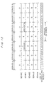
- FIG. 5 shows another practical example of the load-distributed scheduling process.
- the practical example is the scheduling process in which the number ⁇ of the input lines, the output lines, and the scheduler sections 30 is 4.
- the SCH #0 through SCH #3 respectively indicate the four scheduler sections 30 (scheduler sections #0 through #3).
- the 'Scheduling ⁇ Result #0-1' indicates that the scheduling result specified by the '#0-1' is obtained in the scheduling process.
- the scheduling result 'Result #0-1' by the scheduler section #0 (SCH #0) is used.
- SCH #0 scheduling result 'Result #0-1' by the scheduler section #0
- the scheduling results are used by the scheduler sections #0 through #3 at different timings although conflicting scheduling results are obtained, thereby causing no disadvantage. Therefore, it is not necessary to provide a connection line, etc. for conflict control among the scheduler sections #0 through #3. As a result, there is no problem of a signal delay due to the connection line, thereby considerably reducing the restrictions when the switch is installed. Furthermore, since it is necessary only to provide the required number of scheduler sections, the configuration is free of waste. Additionally, since the sections can be added later as necessary, an extensible packet switch 100 can be realized.
- the scheduling results obtained by the ⁇ scheduler sections #0, ..., # ⁇ - 1 are simultaneously transmitted to the respective input buffer sections, and each input buffer section cyclically uses the scheduling results by different scheduler sections every packet hour.
- Described below is the method of distributing the request notifications from the input buffer section 20 to the scheduler section 30.
- FIG. 6 shows a practical example of distributing request notifications for each logic queue VOQ in the input buffer section 20.
- FIGS. 6 through 9 it is assumed that four input buffer sections 20 (#0 through #3) and four scheduler sections 30 (#0 through #3) are provided.
- the request allotment sections #0 through #3 in the input buffer sections #0 through #3 have allotment pointers for each logic queue VOQ, and transmit request notifications to the scheduler sections indicated by the values of the allotment pointers when a packet is transmitted via an input line.
- the pointer values are indicated by the values enclosed by circles in the input buffer sections #0 and #3.
- the request allotment section #0 transmits a request notification to the scheduler section #1 corresponding to the value by referring to the value '1' of the allotment pointer corresponding to the logic queue VOQ #3. After transmitting the request notification, the value of the allotment pointer corresponding to the logic queue VOQ #3 is updated into 2.
- the request allotment section #0 transmits a request notification to the scheduler section #0 corresponding to the value by referring to the value '0' of the allotment pointer corresponding to the logic queue VOQ #0. After transmitting the request notification, the value of the allotment pointer corresponding to the logic queue VOQ #0 is updated into 1.
- the request notifications to be transmitted from the input buffer sections #0 to #N-1 can be distributed among the scheduler sections #0 to # ⁇ -1 by distributing the request notifications generated corresponding to one logic queue VOQ equally to ⁇ scheduler sections #0 to # ⁇ -1.
- FIG. 7 shows a practical example of distributing request notifications for each input line.
- the request allotment sections #0 through #3 in the input buffer sections #0 through #3 have a shared allotment pointer for all logic queues VOQ, and transmit request notifications to the scheduler sections #0 through #3 indicated by the values of the allotment pointers when a packet is transmitted via an input line.
- the pointer values are indicated by the values enclosed by circles in the input buffer sections #0 and #3.
- the request allotment section #0 transmits a request notification to the scheduler section #0 corresponding to the value by referring to the value '0' of the shared allotment pointer. After transmitting the request notification, the value of the allotment pointer is updated into 1.
- each of the input buffer sections #0 through #3 can distribute the request notifications to be transmitted from each of the input buffer sections #0 through #N-1 among the destination scheduler sections #0 through # ⁇ -1 by distributing the request notifications generated corresponding to each logic queue VOQ equally among ⁇ scheduler sections #0 through # ⁇ -1 using a shared allotment pointer.
- FIG. 8 shows a practical example of distributing request notifications for each unit time.
- the request allotment sections #0 through #3 in each of the input buffer sections #0 through #3 has an allotment pointer to be updated for each unit time (for each packet hour), and transmits a request notification to the scheduler section pointed to by the allotment pointer when a packet is received through an input line.
- FIG. 8 shows the pointer value by a value enclosed by a circle in the input buffer sections #0 and #3.
- the request notifications to be transmitted from the input buffer sections #0 through #N-1 can be distributed among the scheduler sections #0 through # ⁇ -1 by distributing the request notifications generated corresponding to each logic queue VOQ equally to ⁇ scheduler sections #0 through # ⁇ -1 using an updated allotment pointer corresponding to arrival time T of packets.
- FIG. 9 shows a practical example of distributing request notifications by the input buffer section 20 referring to the number of requests managed by each scheduler section.
- the request allotment sections #0 through #3 in each of the input buffer sections #0 through #3 refer to the number of the request notifications corresponding to the same combination of an input line and an output line (logic queue VOQ) as the packet in each of the scheduler sections #0 through #3, and determines the scheduler section having the smallest number of requests as the destination of the request notification corresponding to the received packet.
- the number of requests corresponding to the combination of the input line #0 and the logic queue VOQ is shown. Described below are the practical operations of the request allotment section #0 in the input buffer section #0.
- the request allotment section #0 checks the number of the requests indicating the same input line #0 and destination output line #3 (logic queue VOQ #3) by obtaining the information held by the request management sections #0 through #3 in the four scheduler sections #0 through #3, selects the scheduler section 30 having the smallest number of requests, and transmits the request notification to the selected scheduler section.
- each of the input buffer sections #0 through #N-1 obtains the number of requests managed by all scheduler sections #0 through # ⁇ -1, and transmits the request notification to the scheduler section having the smallest number of requests, thereby distributing the request notifications transmitted from each of the input buffer sections #0 through #N-1 equally among the ⁇ scheduler sections #0 through # ⁇ -1.
- Described below is the method of allotting requests when the functions of managing the number of requests are distributed and assigned to both scheduler section 30 and input buffer section 20 without managing the number of requests only by each scheduler section 30. It is assumed that the request number management section 32 in each scheduler section 30 has the request managing function of managing the number of requests for the minimal number.
- the request allotment section 24 in each input buffer section 20 has the function of managing the number of requests transmitted to each scheduler section 30 for each logic queue VOQ (realized by a sub-request counter), and the function of managing the number of requests which have not been notified yet (realized by a request counter).
- the scheduler section 30 having a corresponding logic queue VOQ receiving less than two requests is selected when the request allotment section 24 in the input buffer section 20 transmits a request notification to any of the scheduler sections 30.
- the input buffer section 20 does not transmit a request notification, increments the request counter corresponding to the logic queue VOQ, and transmits the request notification when the number of requests is less than 2.
- FIGS. 10 through 14 show practical examples of distributing and assigning the function of managing the number of requests to the input buffer section 20 and the scheduler section 30.
- one logic queue VOQ #a is considered in the input buffer section #0 corresponding to the input line #0 (i#0) for simple explanation.
- the number of scheduler sections 30 is 4, and the maximum value of the number of managed requests on the scheduler section 30 side is 2.
- the scheduler section #0 (SCH#0) has a request notification corresponding to the input line #0 and the logic queue VOQ #a, and other scheduler sections #1 to #3 (SCH#1 through SCH#3) include two request notifications each.
- the request allotment section #0 transmits a request notification to the scheduler section #0 (SCH#0) having the number of requests of smaller than 2 and having the smallest number of requests, and updates the value of the sub-request counter corresponding to the scheduler section #0 into 2.
- the scheduler section #0 (SCH#0) having the number of requests of smaller than 2 and having the smallest number of requests, and updates the value of the sub-request counter corresponding to the scheduler section #0 into 2.
- the request allotment section #0 does not transmit anew request notification because all scheduler sections #0 through #3 have two request notifications each, but increments the value of the request counter provided to manage the number of the requests which have not been notified yet (FIG. 12).
- the request allotment section #0 detects that the value of the request counter is equal to or larger than 1, and that the value of the sub-request counter corresponding to the scheduler section #2 is smaller than 2, it transmits a request notification to the scheduler section #2.
- the request allotment section #0 increments the value of the sub-request counter corresponding to the scheduler section #2 into 2, and simultaneously decrements the value of the request counter into 0.
- each of the scheduler sections #0 through #3 can perform the scheduling process only by managing a small number of requests, thereby reducing the load of the process performed by the scheduler sections #0 through #3.
- FIG. 15 shows a practical example when the scheduler sections 30 in the redundant system are not fixed. For example, each period corresponds to 4 packet hours, and the number of scheduler sections 30 is 5.
- the 5 scheduler sections #0 through #4 (SCH#0 through SCH#4) are normally operated, they independently perform the scheduling processes, and the scheduling results of all scheduler sections #0 through #4 are cyclically used.
- Each of the scheduler sections #0 through #4 can perform one scheduling process in 4 packet hours. However, in the example shown in FIG. 15, the scheduling result of each of the scheduler sections #0 through #4 is used every 5 packet hours.
- each input buffer section 20 does not use the scheduling result of the scheduler section #1, but cyclically uses only the scheduling results of the other scheduler sections #0, and #2 to #4.
- each of the input buffer sections 20 starts cyclically using the scheduling results of all scheduler sections #0 through #4 from the next period F.
- FIG. 16 shows an example of the operations when the scheduler sections 30 in the redundant system are fixed.
- the scheduler section #4 (SCH#4) is provided in a redundant (standby) system for use only when a error, etc. occurs.
- each of them independently performs the scheduling process, and each of the results of the four scheduler sections #0 through #3 is cyclically used.
- the operations in this case are the same as those performed when the scheduler section #4 of the redundant system is not provided.
- the scheduler section #1 has recovered from the error in the period E, then the scheduler section #4 in the redundant system enters again a standby state, the scheduler section #1 is used, and the scheduling process continues.
- the redundant scheduler sections 30 can replace a faulty section, thereby successfully continuing the scheduling process without delay.
- the maximum switch is set to 4 x 4 (number of input lines x number of output lines)
- the number of the scheduler sections 30 is set to 4
- the scheduling process is performed by a 2 ⁇ 2 packet switch using the above mentioned scheduler section 30.
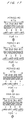
- FIG. 17 shows the outline of the scheduling process with the configuration of the maximum 4 ⁇ 4 packet switch. For example, a scheduling process is performed on one of the four scheduler sections in the round-robin scheduling system.
- the scheduling processes are sequentially performed in the order of the input lines #0, #1, #2, and #3. Since the time required by each of the scheduler sections #0 through #3 is 4 packet hours (1 ⁇ ), each scheduler section obtains a scheduling result every 4 packet hours. In the example shown in FIG. 17, the following scheduling result can be obtained in the period #0.
- the scheduling processes are sequentially performed in the order of the input lines #1, #2, #3, and #0, and the following scheduling results can be obtained.
- the output line corresponding to each input line is determined for each period with the cyclic process order of the target input line in the scheduling process.
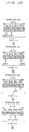
- FIG. 18 shows the outline of scheduling process with the configuration of a small 2 ⁇ 2 packet switch.
- two scheduler sections which are the same as in the maximum configuration are used shown in FIG. 17.
- the scheduling processes are sequentially performed in the order of the input lines #0 and #1.
- Each of the two scheduler sections #0 and #1 has the performance of determining the output line corresponding to each of the four input lines.
- the scheduling processes are performed on these two input lines every 4 packet hours (1 ⁇ ), and the following scheduling results are obtained.
- the scheduling processes are sequentially performed in the order of the input lines #1 and #0, and the following scheduling results are obtained.
- the output line corresponding to each input line is determined for each period with the cyclic process order of the target input line in the scheduling process.
- the throughput is detriorated. That is, the time required to perform the scheduling process by each of the two scheduler sections #0 and #1 is 4 packet hours. In the entire packet switches #0 and #1, two scheduling results are obtained every 4 packet hours. Therefore, for the half of four packet hours, no instruction to transmit a packet can be issued from the scheduler sections #0 and #1 to each of the input buffer sections #0 and #1, thereby halving the throughput deteriorated by half.
- FIG. 19 shows the outline of the scheduling process using a small packet switch with the throughput protected against deterioration.
- the time required to perform the scheduling process by each of the scheduler sections #0 and #1 is set to 2 packet hours. Since the target input lines and output line are halved in number, the required time can be changed.
- the scheduling processes are sequentially performed in the order of the input lines #0 and #1, and the following scheduling results are obtained.
- the scheduling processes are separately performed for the first half and the second half of the period.
- two scheduling results are obtained every 2 packet hours.
- one scheduling result is obtained every packet hour, thereby causing no throughput deterioration.
- FIG. 20 shows the outline of the scheduling process using a small packet switch with the throughput protected against deterioration. For example, a scheduling process is performed with the scheduling time of each of the two scheduler sections still set to 4 packet hours without deteriorating the throughput.
- the underlined input lines #0 and #1 indicate that the scheduling processes are performed for the input lines #2 and #3.
- the output lines #0 and #1 indicates that, when output lines #2 and #3 are obtained as the first destinations of the packets as a scheduling result, they are respectively replaced with the input lines #0 and #1.
- the scheduling processes are sequentially performed in the order of the input lines #0, #1, #2, and #3. Since the time required by each of the scheduler sections #0 and #1 is 4 packet hours (1 ⁇ ), each scheduler section obtains a scheduling result corresponding to the four input lines #0 through #3 every 4 packet hours. As described above, the input lines #2 and #3 are not actually existing, but the scheduling processes are performed on the input lines #0 and #1. As a result, each of the scheduler sections #0 and #1 derives two scheduling results every 4 packet hours. In the example shown in FIG. 20, the following scheduling result can be obtained in the period #0.
- the scheduling processes are sequentially performed in the order of the input lines #1, #2, #3, and #0, and the following scheduling results can be obtained.
- each of the two scheduler sections #0 and #1 derives two scheduling results in 1 period of 4 packet hours.
- a total of four scheduling results can be obtained by the two scheduler sections #0 and #1 every 4 packet hours.
- one scheduling result can be obtained every packet hour, thereby causing no throughput deterioration.
- the packet switch 100 sets the number of the scheduler sections depending on the number of input lines and output lines, and changes the time required for a scheduling process of each scheduler section, thereby avoiding throughput deterioration, and realizing the optimum scheduling process.
- an extensible packet switch can be realized by decreasing a wasteful configuration.
- Described below is a practical example of a scheduling process for deriving a plurality of scheduling results in one period corresponding to a time required for scheduling process by the scheduler section.
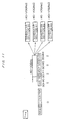
- FIG. 21 shows a practical example of a scheduling process of deriving a plurality of scheduling results in one period, and shows a type of contents of the scheduling process in the period #0 shown in FIG. 20.
- Each of the scheduler sections #0 and #1 manages the existence of a request notification corresponding to the combination of an input line and a logic queue VOQ. For example, for the input line #0, there is a request notification for both output lines #0 and #1. Since a small 2 ⁇ 2 switch is assumed in this example, the input lines #2, #3 and the output lines #2, #3 are not used. Therefore, no request notification instructing one of the input lines #0 and #1 to transmit a packet to one of the output lines #2 and #3 is issued.
- Each scheduler section performs a scheduling process corresponding to an unused line to derive a plurality of scheduling results in a period.
- the contents of the request notification of the input line #0 are set in a block for performing a process corresponding to the input line #2.
- information about a change into the combination of the input line #2 and the output line #2 is set.
- information about a change into the combination of the input line #2 and the output line #3 is set.
- the first scheduling target is the input line #0 on which the scheduling process is performed by selecting one output line which has not been selected and has received a request notification.
- the output line #0 is selected.
- the selected output line #0 is reflected in the unassignment information as having being selected, and then passed to the scheduling process to be performed on the next scheduling target.
- the second scheduling target is the input line #1 on which the scheduling process is performed by selecting one output line which has not been selected and has received a request notification.
- the output line #1 is selected.
- the selected output line #1 is reflected in the unassignment information as having being selected, and then passed to the scheduling process to be performed on the next scheduling target.
- the third scheduling target is the input line #2.
- the request existence information set for the input line #2 corresponds to the input line #0. Therefore, the scheduling process is actually performed on the input line #0.
- the scheduling process on the input line #2 is performed by selecting an output line which has received a request notification and has not been selected yet.
- the output lines which have received a request notification and have not been selected yet are the output line #2 and #3.
- the output line #2 has been selected.
- the selected output line #2 is reflected in the unassignment information as having being selected, and then passed to the scheduling process to be performed on the next scheduling target.
- the output line #2 is actually unused. In the scheduling process performed on such unused lines, a selected output line number is not passed as is to the input buffer section 20, but an output line number is passed after performing a re-reading process. That is, the input line #2 is re-read into the input line #0, and the output line #2 is re-read into the output line #0 and then passed.
- the correspondence between input lines and output lines to be re-read is shown below.
- the scheduling process is performed on the input line #3 which is the fourth scheduling target.
- the output line #3 is selected. Since the input line #3 and the output line #3 are unused lines, they are actually re-read into the input line #1 and the output line #1, and passed to the input buffer section 20.
- a plurality of results can be obtained in one period of the scheduling process by performing the scheduling process using an unused line.
Landscapes
- Engineering & Computer Science (AREA)
- Computer Networks & Wireless Communication (AREA)
- Signal Processing (AREA)
- Data Exchanges In Wide-Area Networks (AREA)
Abstract
Description
- input line #0 (i#0) → output line #2 (o#2)
- input line #1 (i#1) → output line #0 (o#0)
- input line #2 (i#2) → output line #3 (o#3)
- input line #3 (i#3) → output line #1 (o#1)
- input line #0 (i#0) → output line #2 (o#2)
- input line #1 (i#1) → (not transmitted yet)
- input line #2 (i#2) → output line #0 (o#0)
- input line #3 (i#3) → output line #3 (o#3)
- input line #0 (i#0) → (not transmitted yet)
- input line #1 (i#1) → output line #1 (o#1)
- input line #2 (i#2) → output line #0 (o#0)
- input line #3 (i#3) → output line #2 (o#2)
- input line #0 (i#0) → output line #0 (o#0)
- input line #1 (i#1) → output line #2 (o#2)
- input line #2 (i#2) → output line #1 (o#1)
- input line #3 (i#3) → output line #3 (o#3)
- input line #0 (i#0) → output line #0 (o#0)
- input line #1 (i#1) → output line #1 (o#1)
- input line #2 (i#2) → output line #2 (o#2)
- input line #3 (i#3) → output line #3 (o#3)
- input line #1 (i#1) → output line #1 (o#1)
- input line #2 (i#2) → output line #3 (o#3)
- input line #3 (i#3) → output line #2 (o#2)
- input line #0 (i#0) → output line #0 (o#0)
- input line #0 (i#0) → output line #0 (o#0)
- input line #1 (i#1) → output line #1 (o#1)
- input line #1 (i#1) → output line #1 (o#1)
- input line #0 (i#0) → output line #0 (o#0)
- input line #0 (i#0) → output line #0 (o#0)
- input line #1 (i#1) → output line #1 (o#1)
- input line #1 (i#1) → output line #1 (o#1)
- input line #0 (i#0) → output line #0 (o#0)
Claims (12)
- A packet switch, comprising:wherein said N input buffer sections cyclically use results of scheduling processes by said α scheduler sections.N input buffer sections, provided corresponding to N input lines, for storing a packet input through the corresponding input lines;α scheduler sections for determining one of M output lines as a destination of the packet stored in each of said N input buffer sections by a scheduling process independently performed by each scheduler section; anda switch section for outputting the packet output from each of said N input buffer sections to the destination output line determined by said scheduler section,
- The packet switch according to claim 1, wherein:said scheduling process is performed by said scheduler section corresponding to a scheduling request notification transmitted from said N input buffer sections; andeach of said N input buffer sections distributes the scheduling request notifications among said scheduler sections as a destination.
- The packet switch according to claim 2, wherein said input buffer sections have M queues storing packets to be transmitted to the M output lines, and said scheduler sections, which are destinations of the scheduling request notifications, cyclically correspond to the M numbers of each queue.
- The packet switch according to claim 2, wherein said input buffer sections have said scheduler sections, which are destinations of the scheduling request notifications, cyclically correspond to the each input lines.
- The packet switch according to claim 2, wherein said input buffer sections have said scheduler sections, which are destinations of the scheduling request notifications, cyclically correspond to each of a unit time.
- The packet switch according to claim 2, wherein said input buffer sections check a number of unassigned scheduling request notifications for each of said α scheduler sections, and transmit a next scheduling request notification to the scheduler section having smaller number of scheduling request notifications.
- The packet switch according to claim 2, wherein said input buffer sections manage a number of scheduling request notifications transmitted to each of said α scheduler sections, and delay an operation of transmitting the scheduling request notification to the scheduler section whose number of the scheduling request notifications has reached a predetermined value until the number becomes smaller than the predetermined value.
- The packet switch according to claim 1, wherein when a time required by said scheduler section to perform the scheduling process is L times as long as a shortest transmission interval of the packet, the number α of scheduler sections is set to a value equal to or larger than the multiple L.
- The packet switch according to claim 8, wherein:L-α is set to a value equal to or larger than 1; andsaid N input buffer sections cyclically use results of all scheduling processes of said α scheduler sections.
- The packet switch according to claim 8, wherein:L-α is set to a value equal to or larger than 1; andL-α scheduler sections are used as a redundant system, and said scheduler sections in the redundant system replace when a scheduler section which is not included in the sections in the redundant system becomes faulty.
- The packet switch according to claim 1, wherein said number α of said scheduler sections and the time of the scheduling process are set variable depending on the number N of the input lines and the number M of the output lines.
- The packet switch according to claim 1, wherein said scheduler section performs the scheduling process including an unused line, and performs a re-reading process among the actually used input and output lines and the unused lines, thereby obtaining a plurality of scheduling process results by performing one scheduling process.
Applications Claiming Priority (2)
| Application Number | Priority Date | Filing Date | Title |
|---|---|---|---|
| JP2000395741A JP4072315B2 (en) | 2000-12-26 | 2000-12-26 | Packet switch |
| JP2000395741 | 2000-12-26 |
Publications (3)
| Publication Number | Publication Date |
|---|---|
| EP1220497A2 true EP1220497A2 (en) | 2002-07-03 |
| EP1220497A3 EP1220497A3 (en) | 2004-01-21 |
| EP1220497B1 EP1220497B1 (en) | 2005-05-04 |
Family
ID=18861150
Family Applications (1)
| Application Number | Title | Priority Date | Filing Date |
|---|---|---|---|
| EP01119759A Expired - Lifetime EP1220497B1 (en) | 2000-12-26 | 2001-08-28 | Packet switch |
Country Status (4)
| Country | Link |
|---|---|
| US (1) | US7023865B2 (en) |
| EP (1) | EP1220497B1 (en) |
| JP (1) | JP4072315B2 (en) |
| DE (1) | DE60110538T2 (en) |
Families Citing this family (13)
| Publication number | Priority date | Publication date | Assignee | Title |
|---|---|---|---|---|
| US7274697B2 (en) * | 2000-11-16 | 2007-09-25 | Tensilica, Inc. | Fast IP route lookup with 16/K and 16/Kc compressed data structures |
| US6980513B2 (en) * | 2001-09-24 | 2005-12-27 | Transwitch Corporation | Methods and apparatus for the fair allocation of bandwidth among MCR and best effort service connections in an ATM switch |
| US7586909B1 (en) * | 2002-03-06 | 2009-09-08 | Agere Systems Inc. | Striping algorithm for switching fabric |
| DE60305457T2 (en) * | 2003-06-06 | 2007-05-31 | Alcatel | Scheduling unit with optimized jitter and queue storage |
| US7742401B2 (en) * | 2003-08-11 | 2010-06-22 | Netapp, Inc. | Network having switchover with no data loss |
| US7486687B2 (en) * | 2004-02-27 | 2009-02-03 | International Business Machines Corporation | Method and allocation device for allocating pending requests for data packet transmission at a number of inputs to a number of outputs of a packet switching device in successive time slots |
| US7542473B2 (en) * | 2004-12-02 | 2009-06-02 | Nortel Networks Limited | High-speed scheduling apparatus for a switching node |
| JP2007259073A (en) * | 2006-03-23 | 2007-10-04 | Nec Corp | Scheduling apparatus in packet switch |
| US7961630B2 (en) * | 2007-09-27 | 2011-06-14 | Agilent Technologies, Inc. | Methods and apparatus for stimulating packet-based systems |
| JP5416168B2 (en) | 2011-05-19 | 2014-02-12 | 富士通テレコムネットワークス株式会社 | Communication device |
| JP5615764B2 (en) * | 2011-06-15 | 2014-10-29 | 日本電信電話株式会社 | Packet switch and packet scheduling method |
| US10033616B1 (en) | 2014-03-27 | 2018-07-24 | Juniper Networks, Inc. | State synchronization for global control in a distributed security system |
| US20220029936A1 (en) * | 2021-06-01 | 2022-01-27 | Fujitsu Limited | Packet transmission device and packet transmission method |
Family Cites Families (10)
| Publication number | Priority date | Publication date | Assignee | Title |
|---|---|---|---|---|
| JP2994832B2 (en) * | 1992-01-10 | 1999-12-27 | 富士通株式会社 | Failure diagnosis method for UPC circuit |
| US5255265A (en) * | 1992-05-05 | 1993-10-19 | At&T Bell Laboratories | Controller for input-queued packet switch |
| JPH0697965A (en) | 1992-09-14 | 1994-04-08 | Hitachi Ltd | Relay control system for router |
| JPH10173677A (en) * | 1996-12-16 | 1998-06-26 | Toshiba Corp | Physical port flow control method and apparatus in packet communication |
| CA2245367A1 (en) * | 1998-08-19 | 2000-02-19 | Newbridge Networks Corporation | Two-component bandwidth scheduler having application in multi-class digital communication systems |
| JP2000138687A (en) | 1998-10-30 | 2000-05-16 | Toshiba Corp | Relay device |
| US6747971B1 (en) * | 1999-04-20 | 2004-06-08 | Cisco Technology, Inc. | Crosspoint switch with independent schedulers |
| JP3732989B2 (en) * | 2000-01-12 | 2006-01-11 | 富士通株式会社 | Packet switch device and scheduling control method |
| US6813274B1 (en) * | 2000-03-21 | 2004-11-02 | Cisco Technology, Inc. | Network switch and method for data switching using a crossbar switch fabric with output port groups operating concurrently and independently |
| JP3567878B2 (en) * | 2000-10-02 | 2004-09-22 | 日本電気株式会社 | Packet switching equipment |
-
2000
- 2000-12-26 JP JP2000395741A patent/JP4072315B2/en not_active Expired - Fee Related
-
2001
- 2001-08-28 DE DE60110538T patent/DE60110538T2/en not_active Expired - Lifetime
- 2001-08-28 EP EP01119759A patent/EP1220497B1/en not_active Expired - Lifetime
- 2001-08-30 US US09/942,979 patent/US7023865B2/en not_active Expired - Fee Related
Also Published As
| Publication number | Publication date |
|---|---|
| EP1220497B1 (en) | 2005-05-04 |
| DE60110538D1 (en) | 2005-06-09 |
| JP2002198993A (en) | 2002-07-12 |
| US20020080796A1 (en) | 2002-06-27 |
| EP1220497A3 (en) | 2004-01-21 |
| DE60110538T2 (en) | 2006-05-04 |
| US7023865B2 (en) | 2006-04-04 |
| US20030147398A9 (en) | 2003-08-07 |
| JP4072315B2 (en) | 2008-04-09 |
Similar Documents
| Publication | Publication Date | Title |
|---|---|---|
| KR100334922B1 (en) | Efficient output-request packet switch and method | |
| EP1239637B1 (en) | Time based packet scheduling and sorting system | |
| EP1078498B1 (en) | Method and apparatus for supplying requests to a scheduler in an input-buffered multiport switch | |
| US7058057B2 (en) | Network switch port traffic manager having configurable packet and cell servicing | |
| EP0981878B1 (en) | Fair and efficient scheduling of variable-size data packets in an input-buffered multipoint switch | |
| US6839358B2 (en) | Relaying apparatus | |
| US6185221B1 (en) | Method and apparatus for fair and efficient scheduling of variable-size data packets in an input-buffered multipoint switch | |
| US6205118B1 (en) | Adaptive time slot scheduling apparatus and method for end-points in an ATM network | |
| KR100339329B1 (en) | RRGS-Round-Robin Greedy Scheduling for input/output terabit switches | |
| US6091740A (en) | Bandwidth management method and circuit, communication apparatus, communication system, and dual-queue network unit | |
| EP0706298A2 (en) | Dynamic queue length thresholds in a shared memory ATM switch | |
| US7023865B2 (en) | Packet switch | |
| JP2882384B2 (en) | Traffic shaping device | |
| US6574232B1 (en) | Crossbar switch utilizing broadcast buffer and associated broadcast buffer management unit | |
| US5513174A (en) | Telecommunication system with detection and control of packet collisions | |
| EP1013036B1 (en) | Digital traffic switch with credit-based buffer control | |
| GB2381412A (en) | Determining transmission priority for data frames from a plurality of queues | |
| US20070110052A1 (en) | System and method for the static routing of data packet streams in an interconnect network | |
| US7269158B2 (en) | Method of operating a crossbar switch | |
| CN113014465A (en) | Bus transmission interface system based on quality of service characteristics and design method | |
| EP1521411B1 (en) | Method and apparatus for request/grant priority scheduling | |
| JP4164771B2 (en) | Load balance type switch device and load balance type switch method | |
| US6282198B1 (en) | Frequency band control device with cell conflict control | |
| US6105095A (en) | Data packet routing scheduler and method for routing data packets on a common bus | |
| US20040190524A1 (en) | Scheduler device for a system having asymmetrically-shared resources |
Legal Events
| Date | Code | Title | Description |
|---|---|---|---|
| PUAI | Public reference made under article 153(3) epc to a published international application that has entered the european phase |
Free format text: ORIGINAL CODE: 0009012 |
|
| AK | Designated contracting states |
Kind code of ref document: A2 Designated state(s): AT BE CH CY DE DK ES FI FR GB GR IE IT LI LU MC NL PT SE TR |
|
| AX | Request for extension of the european patent |
Free format text: AL;LT;LV;MK;RO;SI |
|
| RIC1 | Information provided on ipc code assigned before grant |
Ipc: 7H 04Q 3/00 B Ipc: 7H 04L 12/56 A |
|
| PUAL | Search report despatched |
Free format text: ORIGINAL CODE: 0009013 |
|
| AK | Designated contracting states |
Kind code of ref document: A3 Designated state(s): AT BE CH CY DE DK ES FI FR GB GR IE IT LI LU MC NL PT SE TR |
|
| AX | Request for extension of the european patent |
Extension state: AL LT LV MK RO SI |
|
| 17P | Request for examination filed |
Effective date: 20040309 |
|
| 17Q | First examination report despatched |
Effective date: 20040503 |
|
| AKX | Designation fees paid |
Designated state(s): DE FR GB |
|
| GRAP | Despatch of communication of intention to grant a patent |
Free format text: ORIGINAL CODE: EPIDOSNIGR1 |
|
| GRAS | Grant fee paid |
Free format text: ORIGINAL CODE: EPIDOSNIGR3 |
|
| GRAA | (expected) grant |
Free format text: ORIGINAL CODE: 0009210 |
|
| AK | Designated contracting states |
Kind code of ref document: B1 Designated state(s): DE FR GB |
|
| REG | Reference to a national code |
Ref country code: GB Ref legal event code: FG4D |
|
| REG | Reference to a national code |
Ref country code: IE Ref legal event code: FG4D |
|
| REF | Corresponds to: |
Ref document number: 60110538 Country of ref document: DE Date of ref document: 20050609 Kind code of ref document: P |
|
| PLBE | No opposition filed within time limit |
Free format text: ORIGINAL CODE: 0009261 |
|
| STAA | Information on the status of an ep patent application or granted ep patent |
Free format text: STATUS: NO OPPOSITION FILED WITHIN TIME LIMIT |
|
| ET | Fr: translation filed | ||
| 26N | No opposition filed |
Effective date: 20060207 |
|
| REG | Reference to a national code |
Ref country code: FR Ref legal event code: PLFP Year of fee payment: 15 |
|
| REG | Reference to a national code |
Ref country code: FR Ref legal event code: PLFP Year of fee payment: 16 |
|
| PGFP | Annual fee paid to national office [announced via postgrant information from national office to epo] |
Ref country code: GB Payment date: 20160824 Year of fee payment: 16 Ref country code: DE Payment date: 20160823 Year of fee payment: 16 |
|
| PGFP | Annual fee paid to national office [announced via postgrant information from national office to epo] |
Ref country code: FR Payment date: 20160712 Year of fee payment: 16 |
|
| REG | Reference to a national code |
Ref country code: DE Ref legal event code: R119 Ref document number: 60110538 Country of ref document: DE |
|
| GBPC | Gb: european patent ceased through non-payment of renewal fee |
Effective date: 20170828 |
|
| REG | Reference to a national code |
Ref country code: FR Ref legal event code: ST Effective date: 20180430 |
|
| PG25 | Lapsed in a contracting state [announced via postgrant information from national office to epo] |
Ref country code: DE Free format text: LAPSE BECAUSE OF NON-PAYMENT OF DUE FEES Effective date: 20180301 Ref country code: GB Free format text: LAPSE BECAUSE OF NON-PAYMENT OF DUE FEES Effective date: 20170828 |
|
| PG25 | Lapsed in a contracting state [announced via postgrant information from national office to epo] |
Ref country code: FR Free format text: LAPSE BECAUSE OF NON-PAYMENT OF DUE FEES Effective date: 20170831 |