EP1220277A2 - Adjusting method for cathode position of an electron gun and an electron gun for a ray tube - Google Patents
Adjusting method for cathode position of an electron gun and an electron gun for a ray tube Download PDFInfo
- Publication number
- EP1220277A2 EP1220277A2 EP01403358A EP01403358A EP1220277A2 EP 1220277 A2 EP1220277 A2 EP 1220277A2 EP 01403358 A EP01403358 A EP 01403358A EP 01403358 A EP01403358 A EP 01403358A EP 1220277 A2 EP1220277 A2 EP 1220277A2
- Authority
- EP
- European Patent Office
- Prior art keywords
- cathode
- grid
- apex point
- electron gun
- holder
- Prior art date
- Legal status (The legal status is an assumption and is not a legal conclusion. Google has not performed a legal analysis and makes no representation as to the accuracy of the status listed.)
- Withdrawn
Links
Images

Classifications
-
- H—ELECTRICITY
- H01—ELECTRIC ELEMENTS
- H01J—ELECTRIC DISCHARGE TUBES OR DISCHARGE LAMPS
- H01J29/00—Details of cathode-ray tubes or of electron-beam tubes of the types covered by group H01J31/00
- H01J29/46—Arrangements of electrodes and associated parts for generating or controlling the ray or beam, e.g. electron-optical arrangement
- H01J29/48—Electron guns
- H01J29/487—Replacing parts of the gun; Relative adjustment of the electrodes
Definitions
- This invention relates to an adjusting method for cathode position of an electron gun and an electron gun for a cathode ray tube. More particularly, after a positional adjustment is executed for a position of an apex point of a cathode to become a center of a grid aperture of a first grid, an adjustment for the distance between the cathode and the first grid is independently executed, and accordingly even a cathode having a dome shaped surface can be fixed to a right position relative to the aperture of the first grid with higher precision.
- An electron gun of a cathode ray tube is so constructed, for example as shown in Fig. 9, as to be mechanically linked and supported with a predetermined positional relation mutually by fixing a cylindrical shaped first grid 11, a second grid 12, a third grid 13, a fourth grid 14 and a fifth grid 15 to a beading glass 16, respectively.
- a cylindrical cathode structure 30 is positioned within the first grid 11 and a cathode 31 is provided on a top surface of the cathode structure 30.
- a grid aperture 11h provided at the first grid 11 and the cathode structure 30 are adjusted to be coaxial and further, a gap between the first grid 11 and the cathode 31 to be a predetermined value (it is called a dgk-value adjustment).
- a test for improving focus characteristics has been done by employing a cathode having a dome shaped surface such as an impregnate type cathode, for example, and by minimizing a work area of a cathode due to concentration of an electronic field from a first grid.
- a position of the apex point of the dome shaped cathode may have dispersion at every cathode.
- the surface of the cathode 31 is dome shaped, so that if it is not precisely adjusted for the gap between the apex point and the first grid 11 to be a predetermined space by properly detecting the position of the apex point of the cathode surface, the gap between the first grid 11 and the cathode 31 may have dispersion, and it causes a problem in which cut-off levels of R, G and B beams have dispersion due to such dispersion of the gaps.
- an adjusting method for a cathode position of an electron gun is presented which is capable of properly adjusting a position of a cathode, although an impregnate type cathode is employed as a cathode.
- the adjusting method of the present invention includes: a step of supporting a cathode structure at a cathode holder; a step of detecting a position of an apex point of the cathode of the cathode structure supported by the cathode holder; a step of fixing the cathode holder to a first grid after executing a position adjustment for the position of the apex point of the cathode to be a center of a grid aperture of the first grid; and a step of fixing the cathode holder and the cathode structure after executing the position adjustment of the detected position of the apex point of the cathode and the first grid to be a predetermined value.
- an electron gun of a cathode ray tube of the present invention comprises: a cathode holder; a cathode structure supported by the cathode holder; a cathode constituting the cathode structure; and a first grid having a grid aperture; wherein an apex point of the cathode is fixed to be positioned to a center of the grid aperture of the first grid.
- a cathode structure having a cathode with a dome shaped surface is mounted within a cathode holder.
- a position of the apex point of the cathode in the cathode structure supported by the cathode holder is detected and then the cathode holder is fixed to the first grid after a position adjustment where a position of an apex point of the cathode is coincided with a center of the grid aperture of the first grid.
- the cathode holder and the cathode structure are fixed after executing the position adjustment in which the gap between the detected position of the apex point of the cathode and the first grid becomes a predetermined value.
- a first grid 11 has a grid aperture 11h-R for R (red) beam, a grid aperture 11h-G for G (green) beam and a grid aperture 11h-B for B (blue) beam.
- a fixing terminal 11T is formed in a projected form, where the first grid 11 is bonded to a beading glass 16 when it is fixed to the beading glass 16.
- a substrate holder 11b is welded to the first grid 11 to support a ceramic substrate 20 as shown in Fig. 1B.
- An insertion aperture 21-R for inserting a cathode structure 30 is provided at the ceramic substrate 20 at a position opposed to the grid aperture 11h-R for the R beam.
- insertion apertures 21-G for G beam and 21-B for B beam for inserting respective cathode structures 30 are provided at positions opposed to the grid aperture 11h-G and grid aperture 11h-B.
- sleeve rings 22-R, 22-G and 22-B are provided on periphery of the insertion apertures 21-R, 21-G and 21-B, respectively on a face of the ceramic substrate 20, which face is the other side of the face opposed to the first grid 11.
- Fig. 2 shows a schematic sectional view of the cathode structure 30 positioned within the first grid 11.
- Such impregnate type cathode 31 having a dome shaped surface is fixed to a cap 32 and further a first sleeve 33 is mounted on the cap 32.
- Each end of three straps 35 is connected to one side of the first sleeve 33 at even intervals and each of the other ends of the straps 35 is connected to a tip of a second sleeve 34, respectively. Accordingly, when the first sleeve 33 to which the cathode 31 and the cap 32 are fixed is inserted into the second sleeve 34, the first sleeve 33 is supported by the straps 35 so as not to move in the direction perpendicular to an axial direction of the cathode structure 30. Furthermore, by fixing the other ends of the straps 35 to the tip of the second sleeve 34, the first sleeve 33 is also kept unmoved to the axial direction of the cathode structure 30.
- the first sleeve 33 is supported by way of the strap 35, so that when the cathode 31 is heated by a heater that is mounted within the first sleeve 33, the heat is prevented from escaping to the second sleeve 34, and accordingly, the cathode 31 can be efficiently heated.
- a sleeve shield 36 is mounted inside the second sleeve 34 to which the first sleeve 33 is connected by way of the straps 35.
- Fig. 3 is a sectional view of a sleeve holder 40 for fixing a cathode structure 30-R for a R (red) beam, a cathode structure 30-G for a G (green) beam and a cathode structure 30-B for a B (blue) beam to the ceramic substrate 30, where the cathode structure 30-R, the cathode structure 30-G and the cathode structure 30-B are inserted into respective inserting apertures 21-R, 21-G and 21-B of the ceramic substrate 20.
- the sleeve holder 40 is formed in a cylindrical shape and an inside diameter of the sleeve holder 40 is formed slightly larger than an outer diameter of the second sleeve 34 so as to slidably support the inserted cathode structure 30. Furthermore, a collar portion 41 to be welded to the sleeve ring 22 is formed at an end of the sleeve holder 40 that becomes a cathode side when the cathode structure 30 is inserted.
- the cathode structure 30 constructed as mentioned above is installed within the first grid 11 by way of the sleeve holder 40, the position of an apex point of the cathode 31 provided on top of the cathode structure 30 and the center of the grid aperture 11h are adjusted to be coincided to each other by a cathode fixing jig, and after that the cathode structure 30 is adjusted to be a right position so as for a gap between the apex point of the cathode 31 and the first grid 11 to be a predetermined value.
- Fig. 4A shows a schematic plan view of the cathode fixing jig
- Fig. 4B is a schematic front view thereof.
- a two-dot-chain line in Fig. 4A and Fig. 4B designates respective positions of a measuring machine 58, a grid position adjustment jig 60 and a cathode structure supporting jig 80, and those will be described later.
- later-described laser output apparatuses 53-2, 53-3, 55-2 and 55-3 are neglected for simplifying the drawings.
- the grid position adjustment jig 60 and a table 52 for mounting the cathode structure supporting jig 80 are provided on a frame 51 of the cathode fixing jig 50.
- Three laser output apparatuses 53-1, 53-2 and 53-3 are provided, for example, for laser-welding the sleeve ring 22 on the ceramic substrate 20 and the collar portion 41 on the sleeve holder 40 around the table 52.
- the laser output apparatus 53-1 is fixed on a supporting substrate 54-1 so as to irradiate the laser beam askew in an upward direction.
- a focus position of the laser beam is adjusted to be a junction face where the sleeve ring 22 of the ceramic substrate 20 supported by the grid position adjustment jig 60 and the collar portion 41 of the sleeve holder 40 supported by the cathode structure supporting jig 80 are in junction.
- the laser output apparatuses 53-2 and 53-3 are also fixed so as to irradiate the laser beam askew in the upward direction, and also are adjusted to have a focus position at a junction face of the sleeve ring 22 and the collar portion 41.
- Three laser output apparatuses 55-1, 55-2 and 55-3 are provided around the table 52 for welding the second sleeve 34 and the sleeve holder 40 of the cathode structure 30, for example.
- the laser output apparatus 55-1 is fixed to the supporting substrate 56-1 to irradiate the laser beam in a horizontal direction.
- a focusing position of the laser beam is adjusted to a superposed position of the second sleeve 34 of the cathode structure 30 supported by the cathode structure supporting jig 80 and the sleeve holder 40 mounted on the ceramic substrate 20.
- the laser output apparatuses 55-2 and 55-3 are also adjusted to irradiate the laser beam to the horizontal direction and the focus point of the laser beam is adjusted to a superposed position of the second sleeve 34 and the sleeve holder 40.
- a measuring machine 58 is positioned above the grid position adjustment jig 60, wherein the measuring machine 58 detects the grid aperture 11h of the first grid 11 supported by the grid position adjustment jig 60 and the position of the apex point of the cathode structure 30 supported by the cathode structure supporting jig 80.
- Fig. 5 shows a schematic front view of the grid position adjustment jig 60.
- the first table 62 is mounted on the base substrate 61 slidably in an X direction in the figure. Furthermore, the second table 63 is mounted on the first table 62 slidably in a Y direction in the figure. Furthermore, a table 64 having an opening 64a is fixedly mounted at the second table 63 for mounting the grid fixing member 70 (as shown by a two-dot-chain line in figure 5). In this case, openings are provided at the base substrate 61, the first table 62 and the second table 63 corresponding to a position of the opening 64a of the table 64.
- a position adjustment apparatus such as a micro-meter 65 is provided at one side of the first table 62 by fixing on the base substrate 61, where such side of the first table 62 is perpendicular to the X direction.
- a spindle 65a of the micro-meter 65 is impinged on a side end face of the first table 62.
- a pressing portion 66 fixed to the base substrate 61 is provided and a shaft 66a of the pressing portion 66 is impinged on the side end face of the first table 62 and then the first table 62 is pressed against the micro-meter 65. Accordingly, the position of the grid fixing member 70 can be adjusted minutely in the X direction by rotating a thimble 65b of the micro-meter 65 so as to vary a protruding amount of the spindle 65a.
- a position adjustment apparatus such as a micro-meter 67 is provided at one side of the second table 63 by fixing on the base substrate 61, where the side of the second table 63 is perpendicular to the X direction.
- a spindle 67a of the micro-meter 67 is impinged on a side end face of the second table 63.
- a pressing portion 68 fixed to the base substrate 61 is provided and a shaft 68a of the pressing portion is impinged on the side end face of the second table 63 and the second table 63 is pressed against the micro-meter 67. Accordingly, the position of the grid fixing member 70 can be adjusted minutely in the X direction by rotating a thimble 67b of the micro-meter 67 so as to vary a protruding amount of the spindle 67a.
- Fig. 6 shows a schematic view of the grid position adjustment jig 60 taken along a line II-II in Fig. 5. Furthermore a schematic sectional view of the opening of the table 64 taken along a line III-III is also depicted.
- An elevating desk 82 is mounted on the base structure 81 slidably in the vertical direction (a Z direction on Figure 6). Furthermore, a micro-meter 83 is fixedly mounted on the base substrate 81 as the position adjustment apparatus and the spindle 83a of the micro-meter 83 is fixed to the elevating desk 82. Furthermore, a supporting portion 84 is provided on an upper surface of the elevating desk 82 for supporting the cathode structure 30 and the sleeve holder 40. In figure 6, a schematic sectional view of the supporting portion 84 is depicted.
- the positions of the cathode structure 30 supported by the supporting portion 84 and the sleeve holder 40 can be adjusted in the vertical direction by rotating the thimble 83b of the micro-meter 83 so as to vary a protruding amount of the spindle 83a of the micro-meter 83.
- the grid fixing member 70 is mounted to the opening of the table 64 in the grid position adjustment jig 60.
- the grid fixing member 70 includes a table 71 to receive the first grid 11 and a supporting lever 72 for supporting the first grid 11 mounted on the table 71.
- the grid aperture 11h of the first grid 11 is open condition at the table 71.
- the grid fixing member 70 is mounted on the grid position adjustment jig 60 and the grid position adjustment jig 60 is further mounted on the cathode structure supporting jig 80 so that the sleeve ring 22 of the ceramic substrate 20 mounted on the first grid 11 becomes to be on a side of the cathode structure supporting jig 80. Furthermore, the position of the grid fixing member 70 is adjusted by the micro-meters 65 and 67 and the cathode 31 of the cathode structure 30 supported by the supporting portion 84 is fixed to be detected by the measuring machine 58 through the grid apertures 11h-R, 11h-G and 11h-B of the first grid 11.
- Figs. 7A to 7D are charts for explaining mounting operations of fixing the cathode structure 30 on the first grid 11 by the cathode fixing jig 50.
- a groove 842 is formed around the cathode structure supporting portion 841 and a resilient member such as a coil spring 843 is loosely inserted in the groove 842.
- a movable supporting member 844 is provided to slidably support the collar portion 41 of the sleeve holder 40 in the vertical direction (the Z direction in the figure), wherein the movable supporting member 844 is loosely inserted in the groove 842 in which the coil spring 843 is loosely inserted.
- the cathode structure 30 when the cathode structure 30 is mounted on the first grid 11, the cathode structure 30 is supported by fixing its position by the cathode structure supporting portion 841, and also, the collar portion 41 of the sleeve holder 40 is supported by the movable supporting member 844. Furthermore, the apex point of the cathode 31 provided at a tip of the cathode structure 30 supported by the supporting portion 84 is detected by the measuring machine 58 by way of the grid aperture 11h-R, for example, of the first grid 11.
- a measuring machine capable of detecting the apex point of the cathode 31 such as a focal depth measuring machine or a three dimensional surface form measuring machine which can detect the apex point by applying interference between an irradiating light and a reflecting light are used a a measuring machine 58.
- the sleeve ring 22 provided on the ceramic substrate 20 and the collar portion 41 of the sleeve holder 40 are bonded by moving the supporting portion 84 in a direction of the first grid 11 as designated by an arrow in Fig. 7B by operating the micro-meter 83. Furthermore, the sleeve ring 22 and the sleeve holder 40 are laser-welded by irradiating a laser beam on this bonding surface from laser output apparatuses 53-1, 53-2 and 53-3.
- a dgk-value (dimension between a grid and a cathode) designating a distance between the surface of the first grid 11 and the apex point of the cathode 30 is adjusted to be a predetermined value by further moving the supporting portion 84 in the direction of the first grid 11 as designated by an arrow in Fig. 7C by further operating the micro-meter 83.
- the dgk-value is easily adjusted to be a predetermined value based on the designated value of the micro-meter 83 with the position of the surface of the first grid 11 as a reference position of the micro-meter 83. Furthermore, when there is dispersion in the height of the apex points, the apex point is detected by the measuring machine 58, and the dgk-value adjustment process is executed to be a predetermined value by measuring the position of the apex point and the surface of the first grid 11.
- the second sleeve 34 and the sleeve holder 40 are laser-welded by irradiating the laser beam from the laser output apparatuses 55-1, 55-2 and 55-3 on the superposed position of the second sleeve 34 of the cathode structure 30 and the sleeve holder 40.
- the cathode structure 30 is to be fixed to the first grid 11 through the sleeve holder 40.
- the supporting portion 84 is moved to a position opposite to the first grid 11 by the micro-meter 83, as shown in Fig. 7D.
- the sleeve ring 22 and the sleeve holder 40 are welded together by the laser beam after the centers of the grid apertures 11h-R, 11h-G and 11h-B are adjusted to be coincided with the apex point by detecting the apex point of the cathode 31. Furthermore, the sleeve holder 40 and the cathode structure 30 are welded together by the laser beam after adjusting the gap between the first grid 11 and the apex point to be a predetermined value. Accordingly, as shown in Fig.
- the sleeve holder 40 and the cathode structure 30 are welded after welding the sleeve ring 22 and the sleeve holder 40, but the sleeve ring 22 and the sleeve holder 40 are able to be welded with a predetermined gap between the first grid 11 and the apex point of the cathode 31 after welding the sleeve holder 40 and the cathode structure 30 by adjusting the center of the grid aperture 11h and the apex point of the cathode 31.
- cathode fixing jig and the grid position adjustment jig are just employed as exemplified models and not limited to the embodiments.
- positional adjustment for the first grid and the position adjustment for the cathode structure are possible to be automated by utilizing signals from the measuring machine or the like.
- a positional adjustment process of the position of the apex point of the cathode and the center of the grid aperture on the first grid is independently done on the dgk-value adjustment process for positioning the gap between the detected position of the apex point of the cathode and the first grid to be a predetermined value. Accordingly, even when a coating type cathode having a dome shaped surface is employed, the mounting operation of the cathode onto the first grid is accomplished with high precision.
Landscapes
- Electrodes For Cathode-Ray Tubes (AREA)
- Manufacture Of Electron Tubes, Discharge Lamp Vessels, Lead-In Wires, And The Like (AREA)
Abstract
In an adjusting method for the cathode position of an electron gun, an apex point of
a dome-shaped cathode (31) is detected and then a positional adjustment is executed by
moving a first grid (11) in a X-Y direction so that the center of a grid aperture (11h-R) is
coincided with the position of the apex point, at first. Next, a sleeve ring (22-R) and a
collar portion (41) of a sleeve holder (40) are welded together by a laser beam. A dgk-value
adjustment is done so as for a gap between first grid (11) and apex point of the
cathode (31) to be a predetermined value and welded by irradiating the laser beam to a
superposed position of the cathode structure (30) and the sleeve. According to the present
invention, the positioning adjustment and the dgk-value adjustment are able to be executed
independently.
Description
- This invention relates to an adjusting method for cathode position of an electron gun and an electron gun for a cathode ray tube. More particularly, after a positional adjustment is executed for a position of an apex point of a cathode to become a center of a grid aperture of a first grid, an adjustment for the distance between the cathode and the first grid is independently executed, and accordingly even a cathode having a dome shaped surface can be fixed to a right position relative to the aperture of the first grid with higher precision.
- An electron gun of a cathode ray tube is so constructed, for example as shown in Fig. 9, as to be mechanically linked and supported with a predetermined positional relation mutually by fixing a cylindrical shaped
first grid 11, asecond grid 12, athird grid 13, afourth grid 14 and afifth grid 15 to abeading glass 16, respectively. - Furthermore, a
cylindrical cathode structure 30 is positioned within thefirst grid 11 and acathode 31 is provided on a top surface of thecathode structure 30. In this case, when thecathode structure 30 is assembled within thefirst grid 11, agrid aperture 11h provided at thefirst grid 11 and thecathode structure 30 are adjusted to be coaxial and further, a gap between thefirst grid 11 and thecathode 31 to be a predetermined value (it is called a dgk-value adjustment). - Furthermore, a test for improving focus characteristics has been done by employing a cathode having a dome shaped surface such as an impregnate type cathode, for example, and by minimizing a work area of a cathode due to concentration of an electronic field from a first grid.
- In a case when the surface of the
cathode 31 is formed to be dome shaped, a position of the apex point of the dome shaped cathode may have dispersion at every cathode. - When the
grid aperture 11h and thecathode structure 30 are adjusted to be coaxial, it sometimes occurs that the position of the apex point and a center of the grid aperture 1 1h are not coincided due to such dispersion of the apex point of thecathode 31. - When the position of the apex point and the center of the
grid aperture 11h are not coincided, a track of a beam emitted from thecathode 31 is bent and it causes the problem that the shift amount of the spot formed on a phosphor screen of the cathode ray tube becomes large. - Furthermore, the surface of the
cathode 31 is dome shaped, so that if it is not precisely adjusted for the gap between the apex point and thefirst grid 11 to be a predetermined space by properly detecting the position of the apex point of the cathode surface, the gap between thefirst grid 11 and thecathode 31 may have dispersion, and it causes a problem in which cut-off levels of R, G and B beams have dispersion due to such dispersion of the gaps. - According to the present invention, an adjusting method for a cathode position of an electron gun is presented which is capable of properly adjusting a position of a cathode, although an impregnate type cathode is employed as a cathode.
- The adjusting method of the present invention includes: a step of supporting a cathode structure at a cathode holder; a step of detecting a position of an apex point of the cathode of the cathode structure supported by the cathode holder; a step of fixing the cathode holder to a first grid after executing a position adjustment for the position of the apex point of the cathode to be a center of a grid aperture of the first grid; and a step of fixing the cathode holder and the cathode structure after executing the position adjustment of the detected position of the apex point of the cathode and the first grid to be a predetermined value.
- Furthermore, an electron gun of a cathode ray tube of the present invention comprises: a cathode holder; a cathode structure supported by the cathode holder; a cathode constituting the cathode structure; and a first grid having a grid aperture; wherein an apex point of the cathode is fixed to be positioned to a center of the grid aperture of the first grid.
- According to the present invention, a cathode structure having a cathode with a dome shaped surface is mounted within a cathode holder. A position of the apex point of the cathode in the cathode structure supported by the cathode holder is detected and then the cathode holder is fixed to the first grid after a position adjustment where a position of an apex point of the cathode is coincided with a center of the grid aperture of the first grid. Furthermore, the cathode holder and the cathode structure are fixed after executing the position adjustment in which the gap between the detected position of the apex point of the cathode and the first grid becomes a predetermined value.
- In the accompanying drawings:
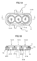
- Fig. 1A is a top view of a first grid;
- Fig. 1B is a sectional view of the first grid taken along a line I-I in Fig. 1A;
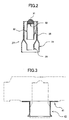
- Fig. 2 is a schematic sectional view of a cathode structure;
- Fig. 3 is a sectional view of a sleeve holder;
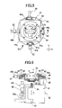
- Fig. 4A is a top view of a cathode fixing jig;
- Fig. 4B is a side view of the cathode fixing jig in Fig. 4A;
- Fig. 5 is a plan view of a grid position adjustment jig;
- Fig. 6 is a sectional view of the grid position adjustment jig taken along a line II-II in Fig. 5 and a cathode structure supporting jig;
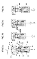
- Figs. 7A to 7D are charts showing a process for assembling the cathode structure;
- Fig. 8 is a schematic sectional view of a first grid on which the cathode structure is mounted; and
- Fig. 9 is a partial side view of the electron gun.
-
- Here-in-after, one embodiment of the present invention is explained with reference to the attached drawings.
- As shown in Fig. 1A, a
first grid 11 has agrid aperture 11h-R for R (red) beam, agrid aperture 11h-G for G (green) beam and agrid aperture 11h-B for B (blue) beam. At a longer side portion of thefirst grid 11, afixing terminal 11T is formed in a projected form, where thefirst grid 11 is bonded to abeading glass 16 when it is fixed to thebeading glass 16. - In addition to the
first grid 11, asubstrate holder 11b is welded to thefirst grid 11 to support aceramic substrate 20 as shown in Fig. 1B. An insertion aperture 21-R for inserting acathode structure 30 is provided at theceramic substrate 20 at a position opposed to thegrid aperture 11h-R for the R beam. Similarly, insertion apertures 21-G for G beam and 21-B for B beam for inserting respective cathode structures 30 (depicted by a two-dot chain line) are provided at positions opposed to thegrid aperture 11h-G andgrid aperture 11h-B. Furthermore, sleeve rings 22-R, 22-G and 22-B are provided on periphery of the insertion apertures 21-R, 21-G and 21-B, respectively on a face of theceramic substrate 20, which face is the other side of the face opposed to thefirst grid 11. - Fig. 2 shows a schematic sectional view of the
cathode structure 30 positioned within thefirst grid 11. Suchimpregnate type cathode 31 having a dome shaped surface is fixed to acap 32 and further afirst sleeve 33 is mounted on thecap 32. - Each end of three
straps 35 is connected to one side of thefirst sleeve 33 at even intervals and each of the other ends of thestraps 35 is connected to a tip of asecond sleeve 34, respectively. Accordingly, when thefirst sleeve 33 to which thecathode 31 and thecap 32 are fixed is inserted into thesecond sleeve 34, thefirst sleeve 33 is supported by thestraps 35 so as not to move in the direction perpendicular to an axial direction of thecathode structure 30. Furthermore, by fixing the other ends of thestraps 35 to the tip of thesecond sleeve 34, thefirst sleeve 33 is also kept unmoved to the axial direction of thecathode structure 30. Thefirst sleeve 33 is supported by way of thestrap 35, so that when thecathode 31 is heated by a heater that is mounted within thefirst sleeve 33, the heat is prevented from escaping to thesecond sleeve 34, and accordingly, thecathode 31 can be efficiently heated. Asleeve shield 36 is mounted inside thesecond sleeve 34 to which thefirst sleeve 33 is connected by way of thestraps 35. - Fig. 3 is a sectional view of a
sleeve holder 40 for fixing a cathode structure 30-R for a R (red) beam, a cathode structure 30-G for a G (green) beam and a cathode structure 30-B for a B (blue) beam to theceramic substrate 30, where the cathode structure 30-R, the cathode structure 30-G and the cathode structure 30-B are inserted into respective inserting apertures 21-R, 21-G and 21-B of theceramic substrate 20. Thesleeve holder 40 is formed in a cylindrical shape and an inside diameter of thesleeve holder 40 is formed slightly larger than an outer diameter of thesecond sleeve 34 so as to slidably support the insertedcathode structure 30. Furthermore, acollar portion 41 to be welded to thesleeve ring 22 is formed at an end of thesleeve holder 40 that becomes a cathode side when thecathode structure 30 is inserted. - When the
cathode structure 30 constructed as mentioned above is installed within thefirst grid 11 by way of thesleeve holder 40, the position of an apex point of thecathode 31 provided on top of thecathode structure 30 and the center of thegrid aperture 11h are adjusted to be coincided to each other by a cathode fixing jig, and after that thecathode structure 30 is adjusted to be a right position so as for a gap between the apex point of thecathode 31 and thefirst grid 11 to be a predetermined value. - Fig. 4A shows a schematic plan view of the cathode fixing jig and Fig. 4B is a schematic front view thereof. A two-dot-chain line in Fig. 4A and Fig. 4B designates respective positions of a measuring
machine 58, a gridposition adjustment jig 60 and a cathodestructure supporting jig 80, and those will be described later. Furthermore, in this schematic front view in Fig. 4 B, later-described laser output apparatuses 53-2, 53-3, 55-2 and 55-3 are neglected for simplifying the drawings. - The grid
position adjustment jig 60 and a table 52 for mounting the cathodestructure supporting jig 80 are provided on aframe 51 of the cathode fixing jig 50. Three laser output apparatuses 53-1, 53-2 and 53-3 are provided, for example, for laser-welding thesleeve ring 22 on theceramic substrate 20 and thecollar portion 41 on thesleeve holder 40 around the table 52. - The laser output apparatus 53-1 is fixed on a supporting substrate 54-1 so as to irradiate the laser beam askew in an upward direction. In addition, a focus position of the laser beam is adjusted to be a junction face where the
sleeve ring 22 of theceramic substrate 20 supported by the gridposition adjustment jig 60 and thecollar portion 41 of thesleeve holder 40 supported by the cathodestructure supporting jig 80 are in junction. Similarly, the laser output apparatuses 53-2 and 53-3 are also fixed so as to irradiate the laser beam askew in the upward direction, and also are adjusted to have a focus position at a junction face of thesleeve ring 22 and thecollar portion 41. - Three laser output apparatuses 55-1, 55-2 and 55-3 are provided around the table 52 for welding the
second sleeve 34 and thesleeve holder 40 of thecathode structure 30, for example. - The laser output apparatus 55-1 is fixed to the supporting substrate 56-1 to irradiate the laser beam in a horizontal direction. A focusing position of the laser beam is adjusted to a superposed position of the
second sleeve 34 of thecathode structure 30 supported by the cathodestructure supporting jig 80 and thesleeve holder 40 mounted on theceramic substrate 20. Similarly, the laser output apparatuses 55-2 and 55-3 are also adjusted to irradiate the laser beam to the horizontal direction and the focus point of the laser beam is adjusted to a superposed position of thesecond sleeve 34 and thesleeve holder 40. - Furthermore, a measuring
machine 58 is positioned above the gridposition adjustment jig 60, wherein the measuringmachine 58 detects thegrid aperture 11h of thefirst grid 11 supported by the gridposition adjustment jig 60 and the position of the apex point of thecathode structure 30 supported by the cathodestructure supporting jig 80. - Fig. 5 shows a schematic front view of the grid
position adjustment jig 60. - The first table 62 is mounted on the
base substrate 61 slidably in an X direction in the figure. Furthermore, the second table 63 is mounted on the first table 62 slidably in a Y direction in the figure. Furthermore, a table 64 having anopening 64a is fixedly mounted at the second table 63 for mounting the grid fixing member 70 (as shown by a two-dot-chain line in figure 5). In this case, openings are provided at thebase substrate 61, the first table 62 and the second table 63 corresponding to a position of theopening 64a of the table 64. - A position adjustment apparatus such as a micro-meter 65 is provided at one side of the first table 62 by fixing on the
base substrate 61, where such side of the first table 62 is perpendicular to the X direction. Aspindle 65a of the micro-meter 65 is impinged on a side end face of the first table 62. Furthermore, apressing portion 66 fixed to thebase substrate 61 is provided and ashaft 66a of thepressing portion 66 is impinged on the side end face of the first table 62 and then the first table 62 is pressed against the micro-meter 65. Accordingly, the position of thegrid fixing member 70 can be adjusted minutely in the X direction by rotating a thimble 65b of the micro-meter 65 so as to vary a protruding amount of thespindle 65a. - A position adjustment apparatus such as a micro-meter 67 is provided at one side of the second table 63 by fixing on the
base substrate 61, where the side of the second table 63 is perpendicular to the X direction. Aspindle 67a of the micro-meter 67 is impinged on a side end face of the second table 63. Furthermore, apressing portion 68 fixed to thebase substrate 61 is provided and ashaft 68a of the pressing portion is impinged on the side end face of the second table 63 and the second table 63 is pressed against the micro-meter 67. Accordingly, the position of thegrid fixing member 70 can be adjusted minutely in the X direction by rotating a thimble 67b of the micro-meter 67 so as to vary a protruding amount of thespindle 67a. - Thus constructed grid
position adjustment jig 60 is mounted and fixed to abase substrate 81 of a cathodestructure supporting jig 80 as shown in Fig. 6. In this case, Fig. 6 shows a schematic view of the gridposition adjustment jig 60 taken along a line II-II in Fig. 5. Furthermore a schematic sectional view of the opening of the table 64 taken along a line III-III is also depicted. - An elevating
desk 82 is mounted on thebase structure 81 slidably in the vertical direction (a Z direction on Figure 6). Furthermore, a micro-meter 83 is fixedly mounted on thebase substrate 81 as the position adjustment apparatus and thespindle 83a of the micro-meter 83 is fixed to the elevatingdesk 82. Furthermore, a supportingportion 84 is provided on an upper surface of the elevatingdesk 82 for supporting thecathode structure 30 and thesleeve holder 40. In figure 6, a schematic sectional view of the supportingportion 84 is depicted. In this case, the positions of thecathode structure 30 supported by the supportingportion 84 and thesleeve holder 40 can be adjusted in the vertical direction by rotating the thimble 83b of the micro-meter 83 so as to vary a protruding amount of thespindle 83a of the micro-meter 83. - The
grid fixing member 70 is mounted to the opening of the table 64 in the gridposition adjustment jig 60. Thegrid fixing member 70 includes a table 71 to receive thefirst grid 11 and a supportinglever 72 for supporting thefirst grid 11 mounted on the table 71. Thegrid aperture 11h of thefirst grid 11 is open condition at the table 71. - The
grid fixing member 70 is mounted on the gridposition adjustment jig 60 and the gridposition adjustment jig 60 is further mounted on the cathodestructure supporting jig 80 so that thesleeve ring 22 of theceramic substrate 20 mounted on thefirst grid 11 becomes to be on a side of the cathodestructure supporting jig 80. Furthermore, the position of thegrid fixing member 70 is adjusted by the micro-meters 65 and 67 and thecathode 31 of thecathode structure 30 supported by the supportingportion 84 is fixed to be detected by the measuringmachine 58 through thegrid apertures 11h-R, 11h-G and 11h-B of thefirst grid 11. - Figs. 7A to 7D are charts for explaining mounting operations of fixing the
cathode structure 30 on thefirst grid 11 by the cathode fixing jig 50. As shown in Fig. 7A, a cathodestructure supporting portion 841 for fixing the position of thecathode structure 30 at a center tip of the supportingportion 84 provided on the cathodestructure supporting jig 80. Furthermore, agroove 842 is formed around the cathodestructure supporting portion 841 and a resilient member such as acoil spring 843 is loosely inserted in thegroove 842. A movable supportingmember 844 is provided to slidably support thecollar portion 41 of thesleeve holder 40 in the vertical direction (the Z direction in the figure), wherein the movable supportingmember 844 is loosely inserted in thegroove 842 in which thecoil spring 843 is loosely inserted. - In this case, when the
cathode structure 30 is mounted on thefirst grid 11, thecathode structure 30 is supported by fixing its position by the cathodestructure supporting portion 841, and also, thecollar portion 41 of thesleeve holder 40 is supported by the movable supportingmember 844. Furthermore, the apex point of thecathode 31 provided at a tip of thecathode structure 30 supported by the supportingportion 84 is detected by the measuringmachine 58 by way of thegrid aperture 11h-R, for example, of thefirst grid 11. - A measuring machine capable of detecting the apex point of the
cathode 31 such as a focal depth measuring machine or a three dimensional surface form measuring machine which can detect the apex point by applying interference between an irradiating light and a reflecting light are useda a measuring machine 58. - A positioning adjustment to execute a fine adjustment of a position of the
first grid 11 by the micro-meters 65 and 67 so that the apex point of thecathode 31 detected by the measuringmachine 58 becomes a center of thegrid aperture 11h-R. - Next, when a fine adjustment of the position of the
first grid 11 is completed, thesleeve ring 22 provided on theceramic substrate 20 and thecollar portion 41 of thesleeve holder 40 are bonded by moving the supportingportion 84 in a direction of thefirst grid 11 as designated by an arrow in Fig. 7B by operating the micro-meter 83. Furthermore, thesleeve ring 22 and thesleeve holder 40 are laser-welded by irradiating a laser beam on this bonding surface from laser output apparatuses 53-1, 53-2 and 53-3. - When the laser welding process for the
sleeve ring 22 and thesleeve holder 40 is completed, a dgk-value (dimension between a grid and a cathode) designating a distance between the surface of thefirst grid 11 and the apex point of thecathode 30 is adjusted to be a predetermined value by further moving the supportingportion 84 in the direction of thefirst grid 11 as designated by an arrow in Fig. 7C by further operating the micro-meter 83. - In this case, when the height of the apex point is constant, the dgk-value is easily adjusted to be a predetermined value based on the designated value of the micro-meter 83 with the position of the surface of the
first grid 11 as a reference position of the micro-meter 83. Furthermore, when there is dispersion in the height of the apex points, the apex point is detected by the measuringmachine 58, and the dgk-value adjustment process is executed to be a predetermined value by measuring the position of the apex point and the surface of thefirst grid 11. - When the dgk-value adjustment process is completed, the
second sleeve 34 and thesleeve holder 40 are laser-welded by irradiating the laser beam from the laser output apparatuses 55-1, 55-2 and 55-3 on the superposed position of thesecond sleeve 34 of thecathode structure 30 and thesleeve holder 40. In this case, thecathode structure 30 is to be fixed to thefirst grid 11 through thesleeve holder 40. Furthermore stress applied to a laser-welded portion of thesleeve ring 22 and thesleeve holder 40 is avoided because the movable supportingmember 844 is to be sliding in thegroove 842, even if the supportingportion 84 is moved in a direction of thefirst grid 11 after the laser-welding of thesleeve ring 22 and thesleeve holder 40. - Furthermore, when the fixing of the
cathode structure 30 to thefirst grid 11 is completed, the supportingportion 84 is moved to a position opposite to thefirst grid 11 by the micro-meter 83, as shown in Fig. 7D. - After that, another
cathode structure 30 is mounted to the supportingportion 84 and thefirst grid 11 is moved to the X direction so that another grid aperture is positioned at thecathode structure 30 supported on the supportingportion 84 and a sequential set of above-described processes as shown in Fig. 7A to Fig. 7D is again executed. - As described above, the
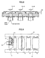
sleeve ring 22 and thesleeve holder 40 are welded together by the laser beam after the centers of thegrid apertures 11h-R, 11h-G and 11h-B are adjusted to be coincided with the apex point by detecting the apex point of thecathode 31. Furthermore, thesleeve holder 40 and thecathode structure 30 are welded together by the laser beam after adjusting the gap between thefirst grid 11 and the apex point to be a predetermined value. Accordingly, as shown in Fig. 8, even if there is dispersion in thecathode structure 30 to be fixed to the position of thegrid aperture 11h-R and the center axis of thegrid aperture 11h-R is not coincided with the position of the apex point, it is possible to adjust the position of the apex point with the center of the grid aperture 1 1h and further to mount thecathode 31 so that the gap between thefirst grid 11 and the apex point becomes a predetermined value. - In this case in the above-described embodiment, the
sleeve holder 40 and thecathode structure 30 are welded after welding thesleeve ring 22 and thesleeve holder 40, but thesleeve ring 22 and thesleeve holder 40 are able to be welded with a predetermined gap between thefirst grid 11 and the apex point of thecathode 31 after welding thesleeve holder 40 and thecathode structure 30 by adjusting the center of thegrid aperture 11h and the apex point of thecathode 31. - Furthermore, the above-mentioned cathode fixing jig and the grid position adjustment jig are just employed as exemplified models and not limited to the embodiments. In addition, the positional adjustment for the first grid and the position adjustment for the cathode structure are possible to be automated by utilizing signals from the measuring machine or the like.
- As described above, a positional adjustment process of the position of the apex point of the cathode and the center of the grid aperture on the first grid is independently done on the dgk-value adjustment process for positioning the gap between the detected position of the apex point of the cathode and the first grid to be a predetermined value. Accordingly, even when a coating type cathode having a dome shaped surface is employed, the mounting operation of the cathode onto the first grid is accomplished with high precision.
Claims (8)
- An adjusting method for a cathode position of an electron gun comprising the steps of :supporting a cathode structure (30) at a cathode holder (40);detecting an apex point of a cathode (31) of said cathode structure (30) supported by said cathode holder (40);fixing said cathode holder (40) to a first grid (11) after executing a position adjustment where the detected position of the apex point of said cathode (31) is positioned at a center of a grid aperture (11h-R) of said first grid (11); andfixing said cathode holder (40) and said cathode structure (30) after executing a gap adjustment where a gap between the detected position of the apex point of said cathode (31) and said first grid (11) becomes to be a predetermined value.
- The adjusting method for a cathode position of an electron gun according to claim 1, wherein
said cathode (31) of the cathode structure (30) has a dome shaped surface. - An adjusting method for a cathode position of an electron gun comprising the steps of:detecting an apex point of a cathode (31) of a cathode structure (30) supported by a cathode holder (40);adjusting the detected position of said apex point to be coincided with a center of a grid aperture (11h-R) of a first grid (11);fixing said cathode holder (40) to said first grid (11);adjusting a gap between said detected position of the apex point of the cathode (31) and said first grid (11); andfixing said cathode holder (40) and said cathode structure (30).
- The adjusting method for a cathode position of an electron gun according to claim 3, wherein
said cathode (31) of the cathode structure (30) has a dome shaped surface. - An electron gun of a cathode ray tube comprising:a cathode holder (40);a cathode structure (30) supported by said cathode holder (40);a cathode (31) constituting said cathode structure (30); anda first grid (11) having a grid aperture (11h-R) whereinan apex point of said cathode (31) is fixed to be positioned to a center of said grid aperture (11h-R) of the first grid (11).
- The electron gun according to claim 5, wherein
said cathode (31) has a dome shaped surface and an apex point of the dome shaped surface is fixed to be positioned to said center of said grid aperture (11h-R) of the first grid (11). - The electron gun according to claim 5, wherein
said cathode (31) is an impregnate type cathode. - The electron gun according to claim 5, wherein
said cathode (31) is a coating type cathode.
Applications Claiming Priority (2)
| Application Number | Priority Date | Filing Date | Title |
|---|---|---|---|
| JP2000391470A JP2002197972A (en) | 2000-12-22 | 2000-12-22 | Method of adjusting cathode position of electron gun |
| JP2000391470 | 2000-12-22 |
Publications (1)
| Publication Number | Publication Date |
|---|---|
| EP1220277A2 true EP1220277A2 (en) | 2002-07-03 |
Family
ID=18857599
Family Applications (1)
| Application Number | Title | Priority Date | Filing Date |
|---|---|---|---|
| EP01403358A Withdrawn EP1220277A2 (en) | 2000-12-22 | 2001-12-24 | Adjusting method for cathode position of an electron gun and an electron gun for a ray tube |
Country Status (3)
| Country | Link |
|---|---|
| US (1) | US6703777B2 (en) |
| EP (1) | EP1220277A2 (en) |
| JP (1) | JP2002197972A (en) |
Cited By (3)
| Publication number | Priority date | Publication date | Assignee | Title |
|---|---|---|---|---|
| CN102672393A (en) * | 2012-05-16 | 2012-09-19 | 安徽华东光电技术研究所 | Assembly fixture for traveling wave tube cathode control assembly and assembly method thereof |
| CN104148862A (en) * | 2014-08-21 | 2014-11-19 | 中国科学院电子学研究所 | Tool fixture for assembling non-intercept grid-controlled electronic gun shadow grid and welding method |
| CN110739195A (en) * | 2019-07-24 | 2020-01-31 | 中国科学院电子学研究所 | A device, system and method for adjusting the coaxiality of cathode and focusing electrode of electron gun |
Families Citing this family (2)
| Publication number | Priority date | Publication date | Assignee | Title |
|---|---|---|---|---|
| JP2004288390A (en) * | 2003-03-19 | 2004-10-14 | Hitachi Displays Ltd | Cathode ray tube |
| US7834553B2 (en) * | 2007-02-05 | 2010-11-16 | Vu1 Corporation | System and apparatus for cathodoluminescent lighting |
Family Cites Families (4)
| Publication number | Priority date | Publication date | Assignee | Title |
|---|---|---|---|---|
| US5402035A (en) * | 1992-09-23 | 1995-03-28 | Goldstar Co., Ltd. | Cathode structure for an electron tube |
| KR200152895Y1 (en) * | 1995-06-21 | 1999-08-02 | 손욱 | Holder for electron gun |
| JP3798551B2 (en) * | 1998-04-23 | 2006-07-19 | 東芝電子エンジニアリング株式会社 | Color cathode ray tube |
| JPH11329290A (en) * | 1998-05-13 | 1999-11-30 | Toshiba Corp | Electron gun for cathode ray tube and method of assembling the same |
-
2000
- 2000-12-22 JP JP2000391470A patent/JP2002197972A/en active Pending
-
2001
- 2001-12-21 US US10/023,647 patent/US6703777B2/en not_active Expired - Fee Related
- 2001-12-24 EP EP01403358A patent/EP1220277A2/en not_active Withdrawn
Cited By (6)
| Publication number | Priority date | Publication date | Assignee | Title |
|---|---|---|---|---|
| CN102672393A (en) * | 2012-05-16 | 2012-09-19 | 安徽华东光电技术研究所 | Assembly fixture for traveling wave tube cathode control assembly and assembly method thereof |
| CN102672393B (en) * | 2012-05-16 | 2014-08-27 | 安徽华东光电技术研究所 | Assembly fixture for traveling wave tube cathode control assembly and assembly method thereof |
| CN104148862A (en) * | 2014-08-21 | 2014-11-19 | 中国科学院电子学研究所 | Tool fixture for assembling non-intercept grid-controlled electronic gun shadow grid and welding method |
| CN104148862B (en) * | 2014-08-21 | 2016-01-20 | 中国科学院电子学研究所 | Frock clamp and the welding method of the assembling of grided electron gun shadow grid is intercepted and captured for nothing |
| CN110739195A (en) * | 2019-07-24 | 2020-01-31 | 中国科学院电子学研究所 | A device, system and method for adjusting the coaxiality of cathode and focusing electrode of electron gun |
| CN110739195B (en) * | 2019-07-24 | 2021-01-15 | 中国科学院电子学研究所 | Cathode and focusing electrode coaxiality adjusting device, system and method of electron gun |
Also Published As
| Publication number | Publication date |
|---|---|
| US6703777B2 (en) | 2004-03-09 |
| US20020084740A1 (en) | 2002-07-04 |
| JP2002197972A (en) | 2002-07-12 |
Similar Documents
| Publication | Publication Date | Title |
|---|---|---|
| US4828523A (en) | Tension mask securement means and process therefore | |
| KR100243796B1 (en) | Narrow neck crt having a large stem pin circle | |
| KR950012700B1 (en) | Cathode-ray tube scanned indepenclently | |
| EP1220277A2 (en) | Adjusting method for cathode position of an electron gun and an electron gun for a ray tube | |
| EP0332262B1 (en) | Method of manufacturing a colour cathode-ray tube and a colour cathode-ray tube | |
| US4950192A (en) | Method of manufacturing of color display tube | |
| US4853584A (en) | Cathode-grid support structure for CRT electron gun | |
| CA1315333C (en) | Method and apparatus of assuring interchangeability of shadow masks and front panels in the manufacture of color cathode ray tubes | |
| US4950945A (en) | Tension mask securement means and process therefor | |
| EP0872871B1 (en) | Color cathode ray tube | |
| CA1222277A (en) | Tensed mask cathode ray tube | |
| US6133675A (en) | Cathode ray tube with integral rear envelope | |
| CA1169479A (en) | Method of manufacturing a colour television display tube and colour television display tube manufactured according to the method | |
| KR102627694B1 (en) | Aperture assembly structure of scanning electron microscope | |
| KR200176399Y1 (en) | An electron gun grid gap measuring device | |
| US5059147A (en) | Method and apparatus for making flat tension mask color cathode ray tubes | |
| KR970000550B1 (en) | Color Award Tube Gun | |
| EP0635863B1 (en) | Electron gun for a cathode ray tube | |
| JPH09330675A (en) | Color cathode ray tube | |
| KR840000489B1 (en) | Manufacturing method of color television display tube | |
| JPS598022B2 (en) | Gun sealing jig for cathode ray tube manufacturing | |
| JPS63304548A (en) | Color cathode-ray tube | |
| JPH10228866A (en) | Manufacturing method of cathode ray tube | |
| KR20030008590A (en) | Manufacturing wethod for fixing frame for shadow mask of flat monitor | |
| KR20010000879U (en) | Stem for cathode ray tube and cathode ray tube having the same |
Legal Events
| Date | Code | Title | Description |
|---|---|---|---|
| PUAI | Public reference made under article 153(3) epc to a published international application that has entered the european phase |
Free format text: ORIGINAL CODE: 0009012 |
|
| AK | Designated contracting states |
Kind code of ref document: A2 Designated state(s): AT BE CH CY DE DK ES FI FR GB GR IE IT LI LU MC NL PT SE TR |
|
| AX | Request for extension of the european patent |
Free format text: AL;LT;LV;MK;RO;SI |
|
| STAA | Information on the status of an ep patent application or granted ep patent |
Free format text: STATUS: THE APPLICATION IS DEEMED TO BE WITHDRAWN |
|
| 18D | Application deemed to be withdrawn |
Effective date: 20040630 |