EP1220096A2 - High performance disk mirroring - Google Patents
High performance disk mirroring Download PDFInfo
- Publication number
- EP1220096A2 EP1220096A2 EP01309417A EP01309417A EP1220096A2 EP 1220096 A2 EP1220096 A2 EP 1220096A2 EP 01309417 A EP01309417 A EP 01309417A EP 01309417 A EP01309417 A EP 01309417A EP 1220096 A2 EP1220096 A2 EP 1220096A2
- Authority
- EP
- European Patent Office
- Prior art keywords
- disk
- data
- disks
- copy
- mirror
- Prior art date
- Legal status (The legal status is an assumption and is not a legal conclusion. Google has not performed a legal analysis and makes no representation as to the accuracy of the status listed.)
- Withdrawn
Links
Images


Classifications
-
- G—PHYSICS
- G06—COMPUTING OR CALCULATING; COUNTING
- G06F—ELECTRIC DIGITAL DATA PROCESSING
- G06F11/00—Error detection; Error correction; Monitoring
- G06F11/07—Responding to the occurrence of a fault, e.g. fault tolerance
- G06F11/16—Error detection or correction of the data by redundancy in hardware
- G06F11/20—Error detection or correction of the data by redundancy in hardware using active fault-masking, e.g. by switching out faulty elements or by switching in spare elements
- G06F11/2053—Error detection or correction of the data by redundancy in hardware using active fault-masking, e.g. by switching out faulty elements or by switching in spare elements where persistent mass storage functionality or persistent mass storage control functionality is redundant
- G06F11/2056—Error detection or correction of the data by redundancy in hardware using active fault-masking, e.g. by switching out faulty elements or by switching in spare elements where persistent mass storage functionality or persistent mass storage control functionality is redundant by mirroring
- G06F11/2087—Error detection or correction of the data by redundancy in hardware using active fault-masking, e.g. by switching out faulty elements or by switching in spare elements where persistent mass storage functionality or persistent mass storage control functionality is redundant by mirroring with a common controller
-
- G—PHYSICS
- G06—COMPUTING OR CALCULATING; COUNTING
- G06F—ELECTRIC DIGITAL DATA PROCESSING
- G06F11/00—Error detection; Error correction; Monitoring
- G06F11/07—Responding to the occurrence of a fault, e.g. fault tolerance
- G06F11/16—Error detection or correction of the data by redundancy in hardware
- G06F11/20—Error detection or correction of the data by redundancy in hardware using active fault-masking, e.g. by switching out faulty elements or by switching in spare elements
- G06F11/2053—Error detection or correction of the data by redundancy in hardware using active fault-masking, e.g. by switching out faulty elements or by switching in spare elements where persistent mass storage functionality or persistent mass storage control functionality is redundant
- G06F11/2056—Error detection or correction of the data by redundancy in hardware using active fault-masking, e.g. by switching out faulty elements or by switching in spare elements where persistent mass storage functionality or persistent mass storage control functionality is redundant by mirroring
- G06F11/2058—Error detection or correction of the data by redundancy in hardware using active fault-masking, e.g. by switching out faulty elements or by switching in spare elements where persistent mass storage functionality or persistent mass storage control functionality is redundant by mirroring using more than 2 mirrored copies
-
- G—PHYSICS
- G06—COMPUTING OR CALCULATING; COUNTING
- G06F—ELECTRIC DIGITAL DATA PROCESSING
- G06F11/00—Error detection; Error correction; Monitoring
- G06F11/07—Responding to the occurrence of a fault, e.g. fault tolerance
- G06F11/16—Error detection or correction of the data by redundancy in hardware
- G06F11/20—Error detection or correction of the data by redundancy in hardware using active fault-masking, e.g. by switching out faulty elements or by switching in spare elements
- G06F11/2053—Error detection or correction of the data by redundancy in hardware using active fault-masking, e.g. by switching out faulty elements or by switching in spare elements where persistent mass storage functionality or persistent mass storage control functionality is redundant
- G06F11/2056—Error detection or correction of the data by redundancy in hardware using active fault-masking, e.g. by switching out faulty elements or by switching in spare elements where persistent mass storage functionality or persistent mass storage control functionality is redundant by mirroring
- G06F11/2071—Error detection or correction of the data by redundancy in hardware using active fault-masking, e.g. by switching out faulty elements or by switching in spare elements where persistent mass storage functionality or persistent mass storage control functionality is redundant by mirroring using a plurality of controllers
Definitions
- the present invention relates to high performance disk mirroring.
- the typical computer disk drive includes a stack of one or more circular platters and at least one mechanical arm with a read/write head for each surface of each of the platters.
- the read/write heads read data from or write data to circular tracks on the platters as the platters rotate.
- the term "cylinder" is often used to describe a set of circular tracks, all lying on different disk surfaces at the same radial distance from the centers of the platters.
- the mechanical arm positions the corresponding read/write head to the track that stores the data.
- This movement of the read/write head to the appropriate track is generally called a "seek."
- the read/write head accesses the targeted block of data when that block rotates to the position of the read/write head.
- the amount of time required for completing a read or write operation is dominated by the seek-time of the read/write head, the rotation time of the disk, and the data-transfer time.
- the seek-time is a function of the physical distance traveled by the mechanical arm in moving to the appropriate track.
- Short-stroking is a disk-access technique that involves confining the range-of-movement of the mechanical arm to a small portion of the available cylinders in a disk drive, usually those lying only on the outer tracks of the disks in the drive. Short-stroking improves performance by reducing the distance traveled by the mechanical arm during most disk accesses and thus reducing average seek-time.
- Mirroring involves storing a primary copy of data on one disk and a duplicate copy, or "mirror,” on another disk drive.
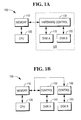
- FIG. 1A shows a computing system 100 that uses mirroring to ensure the integrity and availability of data.
- the system 100 includes one or more central processing units (CPU), or processors 105, that perform certain operations on data in the system.
- processors 105 executes program instructions that are stored, at least temporarily, in one or more volatile or non-volatile memory devices 110, such as a random-access memory (RAM) or read-only memory (ROM) chipset.
- RAM random-access memory
- ROM read-only memory
- Much of the data provided to and produced by the processor 105 during these operations is stored on the disk drives 115, 120 in one or more disk subsystems 125.
- a hardware controller 130 governs the manner and locations in which data is stored on the disk drives 115, 120.
- FIG. 1B shows an implementation in which the mirrored disk drives 115, 120 are managed by separate hardware controllers 130, 132.
- FIG. 2 shows a common mirroring technique, in which one disk drive 115 serves as the primary disk and another disk drive 120 serves as the mirror disk.
- the mirror disk 120 stores a mirror copy of all or some portion of the data stored on the primary disk 115.
- the disk controller makes essentially the entire surface of each disk available for data storage.
- the read/write heads must seek over the entire surface of the primary disk 115 for many read and write operations and must seek over the entire surface of the mirror disk 120 for many write operations. Because all read operations are directed to the primary disk 115, this technique subjects the primary disk to much heavier use than the mirror disk 120.
- FIG. 3 shows a mirroring technique that offers better performance than the technique shown in FIG. 1.
- This technique uses the short-stroking effect to limit the distance traveled by the read/write heads and therefore to reduce the seek-time associated with the disks 115, 120.
- the disk controller stores data only on the outer portions 135, 140 of the disks 115, 120, leaving the inner portions 145, 150 of the disks unused.
- the disk controller stores the primary copy of all data on one disk 115 and the mirror copy on another disk 120. Therefore, this technique also subjects one of the disks to much heavier use than the other.
- FIG. 4 shows another mirroring technique that relies on the short-stroking effect.
- the disk controller divides the recording tracks on each disk into distinct groups, or extents, and stores primary and mirror copies of data on alternating extents on each disk.
- the disk controller stores the primary copy of one set of data on the outer tracks, or outer extent 155, of one of the disks 115 ("Disk A") and stores the mirror copy of that data on the outer extent 160 of the other disk 120 ("Disk B").
- the disk controller then stores the primary copy of another set of data on the inner tracks, or inner extent 165, of Disk B and stores the mirror copy of that data on the inner extent 170 of Disk A.
- This technique more evenly distributes the workloads of the two disks by placing primary copies of data on both disks, thus ensuring that read operations are directed to both disks.
- the short-stroking techniques shown in FIG. 3 and FIG.4 improve disk-drive performance, as described above, by limiting the distance over which the read/write heads must travel to access data. However, these techniques also leave a large portion of each disk unused, reducing the total storage capacity of the disk drive and thus driving up the cost of disk storage in the system.
- the primary copy and the mirror copy of each block of data start at the same relative positions, or track offsets, on their respective disks.
- a set of storage disks includes a mirrored pair of disks.
- Each disk in the pair includes a mirror copy of data stored on the other disk in the pair.
- the data forming the mirror copy is physically located between the physical center of the disk and the data that is mirrored on the other disk.
- a set of storage disks comprising a mirrored pair of disks, where each disk in the pair includes a mirror copy of data stored on the other disk in the pair, such that, on each of the disks in the pair, the data forming the mirror copy is physically located between the center of the disk and the data that is mirrored on the other disk.
- a method for use in storing data on a mirrored pair of storage disks comprising, for each disk:
- a storage subsystem for use in storing data on at least two storage disks, where the storage subsystem is configured to:
- a storage subsystem for use in storing data on a mirrored pair of disks, where the storage subsystem is configured to store, on each disk in the pair, a mirror copy of data that is stored on the other disk in the pair, such that, on each of the disks in the pair, the data forming the mirror copy is physically located between the center of the disk and the data that is mirrored on the other disk.
- a method for use in storing data on at least two storage disks comprising:
- a data-storage-and-retrieval system comprising:
- FIG. 5 shows a disk-mirroring technique that provides the performance benefits of short-stroking without sacrificing the storage capacity of the mirrored disks 200, 205.
- One or more storage subsystems each including a disk controller similar to that shown in FIG. 1 above, store data across the surfaces of the disks in a manner that ensures that most access operations are directed to the outer portions of the disks.
- the storage subsystem divides each of the mirrored disks 200, 205 into at least two extents. All extents lying on the outer portions of the disks are used to store primary copies of data. All extents lying on the inner portions of the disks are used to store mirror copies of that data.
- the primary and mirror copies of each data block are stored at different relative positions, or track offsets, on their respective disks. In most embodiments, the relative positions of the primary and mirror copies differ significantly.
- each disk drive 200, 205 is divided into two extents - one extent 210, 215 that includes the tracks lying on the outer half of the drive and one extent 220, 225 that includes the tracks lying on the inner half of the drive.
- the outer extent 210 on one of the drives (“Disk A”) is used to store the primary copy of a set of data.
- the mirror copy of that data is stored on the inner extent 225 of the other drive (“Disk B").
- the outer extent 215 of Disk B is used to store the primary copy of another set of data, while the inner extent 220 of Disk A stores the mirror copy of that data.
- Storing the data in this manner provides the benefits of short-stroking for most disk-access operations, yet still allows the system to use the full-storage capacity of each disk.
- all read operations and one-half of write operations are directed to the outer halves of the disks.
- the disk controller directs only one-half of all write operations to tracks on the inner halves of the disks.
- the storage subsystem allocates a certain amount of space on each disk for primary data and a certain amount for mirror data. In some embodiments, the storage subsystem makes these allocations with knowledge of the characteristics of the data to be stored and thus allocates space accordingly. In other embodiments, the storage subsystem makes these allocations without any information about the data to be stored. In some embodiments, a human user determines how to allocate space on the disks and instructs the storage subsystem to allocate space accordingly.
- FIG. 6 shows one technique for writing data to a pair of mirrored disks.
- the storage subsystem first receives a block of data along with an instruction to write that data to the disk drive (step 300).
- the subsystem stores the data to the outer tracks of one disk (“Disk A”) (step 305) and to the inner tracks of the other disk (“Disk B”) (step 310).
- Disk A serves as the primary
- Disk B serves as the mirror.
- the storage subsystem receives another block of data with a request to write that data to the disk drive (step 315).
- the subsystem stores this data to the outer tracks of Disk B (step 320) and to the inner tracks of Disk A (step 325).
- Disk B serves as the primary
- Disk A serves as the mirror.
- the storage subsystem Upon receiving other write requests, the storage subsystem repeats these steps, storing data to the outer half of one disk and to the inner half of the other disk.
- the storage subsystem treats all of the data on the outer half of each disk as the primary copy and all of the data on the inner half of each disk as the mirror copy.
- write requests are not necessarily handled in the serial manner shown here.
- the storage subsystem often executes many concurrent write requests in an order other than that in which the subsystem receives the requests.
- FIG. 7 shows a technique for reading data from the mirrored disks.
- the requesting device (CPU, I/O bus, etc. ) delivers a read request to the storage subsystem (step 350).
- the storage subsystem responds by attempting to read the data from the outer tracks of the primary disk (step 355). If the subsystem is not successful in reading data from the primary disk (step 360), it reads the data from the inner tracks of the mirror disk (step 365).
- the storage subsystem Upon successfully reading the requested data from either the primary or mirror disk, the storage subsystem delivers the data to the requesting device, along with a notification that the read was successful (step 370).
- FIG. 8 shows a data-storage-and-retrieval system 400, such as a high-end data warehousing system, in which the disk mirroring technique described here is particularly useful.
- the system 400 includes one or more computing nodes 405 1...N that manage the storage and retrieval of data in one or more data-storage facilities 410 1...M .
- Each of the computing nodes 405 1...N is driven by a processing subsystem 415 1...N that includes one or more processing units, or CPUs. In general, all of the CPUs within a node share operating system and memory resources.
- the processing subsystem 415 1...N operates under the control of at least one instance 420 1...N of a database-management system (DBMS) program.
- DBMS database-management system
- each node runs several instances of the DBMS program, each forming a virtual processor that is assigned to manage some subset of the data in the storage facilities.
- Each DBMS process manages the assigned data in the database and governs access to the data by performing a prescribed set of operations on the data.
- a user initiates these operations by delivering instructions through a remote computer system, such as a mainframe 430 connected directly to the database system or a client system 435 connected through a network 440.
- the user typically enters the instructions using a prescribed database-query language, such as the Structured Query Language (SQL) put forth by the American National Standards Institute (ANSI).
- SQL Structured Query Language
- Each of the data-storage facilities 410 1...M includes an array of mirrored disk drives. Information requested by the mainframe 430 and client system 435 is retrieved from these disk drives by the computing nodes 405 1...N . Quicker data retrieval in the data-storage facilities 410 1...M produces lower query-response times and thus improves overall system performance. Also, because the cost of the data-storage facilities 410 1...M is a significant component of overall system cost, more effective use of disk-storage capacity provides significant cost-savings opportunities.
- the text above describes one or more specific embodiments of a broader invention.
- the invention also is carried out in a variety of alternative embodiments and thus is not limited to those described here.
- the mirrored disks are located in different storage subsystems and are managed by different disk controllers.
- computer software is used to carry out the disk-mirroring scheme ("software mirroring").
- each disk drive in a mirrored set includes more than one primary extent and more than one mirror extent.
- the storage subsystems attempt to spread the primary and mirror extents evenly among the disks in the mirrored set. Regardless of the number of extents on a disk, the storage subsystem places the primary extents on outer tracks and the mirror extents on inner tracks. Except for specific situations in which greater performance or disk-utilization improvements might result, all of the mirror extents on each disk lie between the innermost primary extent and the center point, or physical center, of the disk.
- the mirrored sets do not include exactly two disk drives. Some systems distribute primary and mirror extents over a greater number of disks. Many other modifications may be incorporated with the scope of the present invention.
Landscapes
- Engineering & Computer Science (AREA)
- Theoretical Computer Science (AREA)
- Quality & Reliability (AREA)
- Physics & Mathematics (AREA)
- General Engineering & Computer Science (AREA)
- General Physics & Mathematics (AREA)
- Information Retrieval, Db Structures And Fs Structures Therefor (AREA)
- Signal Processing For Digital Recording And Reproducing (AREA)
- Management Or Editing Of Information On Record Carriers (AREA)
Abstract
Description
- The present invention relates to high performance disk mirroring.
- The typical computer disk drive includes a stack of one or more circular platters and at least one mechanical arm with a read/write head for each surface of each of the platters. The read/write heads read data from or write data to circular tracks on the platters as the platters rotate. The term "cylinder" is often used to describe a set of circular tracks, all lying on different disk surfaces at the same radial distance from the centers of the platters.
- In accessing a block of addressed data on a particular surface, the mechanical arm positions the corresponding read/write head to the track that stores the data. This movement of the read/write head to the appropriate track is generally called a "seek." The read/write head accesses the targeted block of data when that block rotates to the position of the read/write head. The amount of time required for completing a read or write operation is dominated by the seek-time of the read/write head, the rotation time of the disk, and the data-transfer time. The seek-time is a function of the physical distance traveled by the mechanical arm in moving to the appropriate track.
- "Short-stroking" is a disk-access technique that involves confining the range-of-movement of the mechanical arm to a small portion of the available cylinders in a disk drive, usually those lying only on the outer tracks of the disks in the drive. Short-stroking improves performance by reducing the distance traveled by the mechanical arm during most disk accesses and thus reducing average seek-time.
- Many data-storage systems ensure data integrity and availability by "mirroring" the data stored on each disk. Mirroring involves storing a primary copy of data on one disk and a duplicate copy, or "mirror," on another disk drive.
- FIG. 1A shows a
computing system 100 that uses mirroring to ensure the integrity and availability of data. Thesystem 100 includes one or more central processing units (CPU), orprocessors 105, that perform certain operations on data in the system. Eachprocessor 105 executes program instructions that are stored, at least temporarily, in one or more volatile ornon-volatile memory devices 110, such as a random-access memory (RAM) or read-only memory (ROM) chipset. Much of the data provided to and produced by theprocessor 105 during these operations is stored on thedisk drives more disk subsystems 125. In each subsystem, ahardware controller 130 governs the manner and locations in which data is stored on thedisk drives disk drives separate hardware controllers - FIG. 2 shows a common mirroring technique, in which one
disk drive 115 serves as the primary disk and anotherdisk drive 120 serves as the mirror disk. Themirror disk 120 stores a mirror copy of all or some portion of the data stored on theprimary disk 115. In this example, the disk controller makes essentially the entire surface of each disk available for data storage. As a result, the read/write heads must seek over the entire surface of theprimary disk 115 for many read and write operations and must seek over the entire surface of themirror disk 120 for many write operations. Because all read operations are directed to theprimary disk 115, this technique subjects the primary disk to much heavier use than themirror disk 120. - FIG. 3 shows a mirroring technique that offers better performance than the technique shown in FIG. 1. This technique uses the short-stroking effect to limit the distance traveled by the read/write heads and therefore to reduce the seek-time associated with the
disks outer portions disks inner portions - As with the technique shown in FIG. 1, the disk controller stores the primary copy of all data on one
disk 115 and the mirror copy on anotherdisk 120. Therefore, this technique also subjects one of the disks to much heavier use than the other. - FIG. 4 shows another mirroring technique that relies on the short-stroking effect. With this technique, the disk controller divides the recording tracks on each disk into distinct groups, or extents, and stores primary and mirror copies of data on alternating extents on each disk. In the example shown here, the disk controller stores the primary copy of one set of data on the outer tracks, or
outer extent 155, of one of the disks 115 ("Disk A") and stores the mirror copy of that data on theouter extent 160 of the other disk 120 ("Disk B"). The disk controller then stores the primary copy of another set of data on the inner tracks, orinner extent 165, of Disk B and stores the mirror copy of that data on theinner extent 170 of Disk A. This technique more evenly distributes the workloads of the two disks by placing primary copies of data on both disks, thus ensuring that read operations are directed to both disks. - The short-stroking techniques shown in FIG. 3 and FIG.4 improve disk-drive performance, as described above, by limiting the distance over which the read/write heads must travel to access data. However, these techniques also leave a large portion of each disk unused, reducing the total storage capacity of the disk drive and thus driving up the cost of disk storage in the system. In all of the techniques of FIGS. 2-4, the primary copy and the mirror copy of each block of data start at the same relative positions, or track offsets, on their respective disks.
- A set of storage disks includes a mirrored pair of disks. Each disk in the pair includes a mirror copy of data stored on the other disk in the pair. For each of the disks in the pair, the data forming the mirror copy is physically located between the physical center of the disk and the data that is mirrored on the other disk.
- According to a first aspect of the present invention a set of storage disks comprising a mirrored pair of disks, where each disk in the pair includes a mirror copy of data stored on the other disk in the pair, such that, on each of the disks in the pair, the data forming the mirror copy is physically located between the center of the disk and the data that is mirrored on the other disk.
- According to a second aspect of the present invention a method for use in storing data on a mirrored pair of storage disks, the method comprising, for each disk:
- storing data on the disk; and
- storing a mirror copy of that data on the other disk;
- such that on each disk the mirror copy is physically located between the center of the disk and the data that is mirrored on the other disk.
-
- According to a third aspect of the present invention there is provided a storage subsystem for use in storing data on at least two storage disks, where the storage subsystem is configured to:
- store a primary copy of a set of data at a selected track offset on one of the disks;
- store a mirror copy of the data on the other disk at a track offset that differs substantially from the track offset at which the primary copy is stored; and
- store, on the disk that includes the primary copy of the data, a primary copy of at least one other set of data at a track offset that lies between the selected track offset and the track offset at which the mirror copy is stored on the other disk.
-
- According to a further aspect of the present invention there is provided a storage subsystem for use in storing data on a mirrored pair of disks, where the storage subsystem is configured to store, on each disk in the pair, a mirror copy of data that is stored on the other disk in the pair, such that, on each of the disks in the pair, the data forming the mirror copy is physically located between the center of the disk and the data that is mirrored on the other disk.
- According to a further aspect of the present invention there is provided a method for use in storing data on at least two storage disks, the method comprising:
- storing a primary copy of a set of data at a selected track offset on one of the disks;
- storing a mirror copy of the data on the other disk at a track offset that differs substantially from the track offset at which the primary copy is stored; and
- storing, on the disk that includes the primary copy of the data, a primary copy of at least one other set of data at a track offset that lies between the selected track offset and the track offset at which the mirror copy is stored on the other disk.
-
- According to a further aspect of the present invention there is provided a data-storage-and-retrieval system comprising:
- one or more processing subsystems configured to carry out data processing operations; and
- a storage subsystem configured to store data requested or produced by the processing subsystems, where the storage subsystem includes a mirrored pair of disks, each including a mirror copy of data stored on the other disk in the pair, such that, on each of the disks in the pair, the data forming the mirror copy is physically located between the center of the disk and the data that is mirrored on the other disk.
-
- Prior art disks and methods of operation as disclosed in figures 1 to 4 as follows:
- FIGS. 1A and 1B are generalized block diagrams of a computer system; and
- FIGS. 2, 3, and 4 are schematic diagrams showing three conventional techniques for storing data on mirrored disks.
-
- An embodiment of the present invention will now be described, by way of example, with reference to the accompanying drawings, in which:
- FIG. 5 is a schematic diagram showing a new technique for storing data on mirrored disks;
- FIGS. 6 and 7 are flow charts of techniques for writing and reading data on mirrored disks; and
- FIG. 8 is a block diagram of a data-storage-and-retrieval system.
-
- FIG. 5 shows a disk-mirroring technique that provides the performance benefits of short-stroking without sacrificing the storage capacity of the mirrored
disks disks - For example, in FIG. 5, each
disk drive extent extent outer extent 210 on one of the drives ("Disk A") is used to store the primary copy of a set of data. The mirror copy of that data is stored on theinner extent 225 of the other drive ("Disk B"). Likewise, theouter extent 215 of Disk B is used to store the primary copy of another set of data, while theinner extent 220 of Disk A stores the mirror copy of that data. - Storing the data in this manner provides the benefits of short-stroking for most disk-access operations, yet still allows the system to use the full-storage capacity of each disk. For a mirrored pair of disks on which the primary extents cover exactly half of each disk's capacity and for which access patterns are random, all read operations and one-half of write operations are directed to the outer halves of the disks. The disk controller directs only one-half of all write operations to tracks on the inner halves of the disks.
- The storage subsystem allocates a certain amount of space on each disk for primary data and a certain amount for mirror data. In some embodiments, the storage subsystem makes these allocations with knowledge of the characteristics of the data to be stored and thus allocates space accordingly. In other embodiments, the storage subsystem makes these allocations without any information about the data to be stored. In some embodiments, a human user determines how to allocate space on the disks and instructs the storage subsystem to allocate space accordingly.
- FIG. 6 shows one technique for writing data to a pair of mirrored disks. The storage subsystem first receives a block of data along with an instruction to write that data to the disk drive (step 300). The subsystem stores the data to the outer tracks of one disk ("Disk A") (step 305) and to the inner tracks of the other disk ("Disk B") (step 310). For this data, Disk A serves as the primary and Disk B serves as the mirror.
- At some point after the first write request arrives, the storage subsystem receives another block of data with a request to write that data to the disk drive (step 315). The subsystem stores this data to the outer tracks of Disk B (step 320) and to the inner tracks of Disk A (step 325). For this data, Disk B serves as the primary and Disk A serves as the mirror.
- Upon receiving other write requests, the storage subsystem repeats these steps, storing data to the outer half of one disk and to the inner half of the other disk. The storage subsystem treats all of the data on the outer half of each disk as the primary copy and all of the data on the inner half of each disk as the mirror copy.
- In practice, write requests are not necessarily handled in the serial manner shown here. The storage subsystem often executes many concurrent write requests in an order other than that in which the subsystem receives the requests.
- FIG. 7 shows a technique for reading data from the mirrored disks. The requesting device (CPU, I/O bus, etc.) delivers a read request to the storage subsystem (step 350). The storage subsystem responds by attempting to read the data from the outer tracks of the primary disk (step 355). If the subsystem is not successful in reading data from the primary disk (step 360), it reads the data from the inner tracks of the mirror disk (step 365). Upon successfully reading the requested data from either the primary or mirror disk, the storage subsystem delivers the data to the requesting device, along with a notification that the read was successful (step 370).
- FIG. 8 shows a data-storage-and-
retrieval system 400, such as a high-end data warehousing system, in which the disk mirroring technique described here is particularly useful. Thesystem 400 includes one or more computing nodes 4051...N that manage the storage and retrieval of data in one or more data-storage facilities 4101...M. Each of the computing nodes 4051...N is driven by a processing subsystem 4151...N that includes one or more processing units, or CPUs. In general, all of the CPUs within a node share operating system and memory resources. - Within each node, the processing subsystem 4151...N operates under the control of at least one instance 4201...N of a database-management system (DBMS) program. In a data warehousing system built on a massively parallel processing (MPP) platform, each node runs several instances of the DBMS program, each forming a virtual processor that is assigned to manage some subset of the data in the storage facilities. Each DBMS process manages the assigned data in the database and governs access to the data by performing a prescribed set of operations on the data. In general, a user initiates these operations by delivering instructions through a remote computer system, such as a
mainframe 430 connected directly to the database system or aclient system 435 connected through anetwork 440. The user typically enters the instructions using a prescribed database-query language, such as the Structured Query Language (SQL) put forth by the American National Standards Institute (ANSI). - Each of the data-storage facilities 4101...M includes an array of mirrored disk drives. Information requested by the
mainframe 430 andclient system 435 is retrieved from these disk drives by the computing nodes 4051...N. Quicker data retrieval in the data-storage facilities 4101...M produces lower query-response times and thus improves overall system performance. Also, because the cost of the data-storage facilities 4101...M is a significant component of overall system cost, more effective use of disk-storage capacity provides significant cost-savings opportunities. - The text above describes one or more specific embodiments of a broader invention. The invention also is carried out in a variety of alternative embodiments and thus is not limited to those described here. For example, in many systems, the mirrored disks are located in different storage subsystems and are managed by different disk controllers. In these situations, computer software is used to carry out the disk-mirroring scheme ("software mirroring").
- In some embodiments, each disk drive in a mirrored set includes more than one primary extent and more than one mirror extent. In most of these systems, the storage subsystems attempt to spread the primary and mirror extents evenly among the disks in the mirrored set. Regardless of the number of extents on a disk, the storage subsystem places the primary extents on outer tracks and the mirror extents on inner tracks. Except for specific situations in which greater performance or disk-utilization improvements might result, all of the mirror extents on each disk lie between the innermost primary extent and the center point, or physical center, of the disk.
- In many systems, the mirrored sets do not include exactly two disk drives. Some systems distribute primary and mirror extents over a greater number of disks. Many other modifications may be incorporated with the scope of the present invention.
Claims (8)
- A set of storage disks comprising a mirrored pair of disks, where each disk in the pair includes a mirror copy of data stored on the other disk in the pair, such that, on each of the disks in the pair, the data forming the mirror copy is physically located between the center of the disk and the data that is mirrored on the other disk.
- A set of storage disks as claimed in claim 1, where at least one of the disks in the pair includes mirror copies of at least two sets of data stored on the other disk in the pair.
- A set of storage disks as claimed in claim 1, where, on each disk in the pair, all data that forms a mirror copy is physically located between the center of the disk and all other data stored on the disk.
- A method for use in storing data on a mirrored pair of storage disks, the method comprising, for each disk:storing data on the disk; andstoring a mirror copy of that data on the other disk;such that on each disk the mirror copy is physically located between the center of the disk and the data that is mirrored on the other disk.
- A storage subsystem for use in storing data on at least two storage disks, where the storage subsystem is configured to:store a primary copy of a set of data at a selected track offset on one of the disks;store a mirror copy of the data on the other disk at a track offset that differs substantially from the track offset at which the primary copy is stored; andstore, on the disk that includes the primary copy of the data, a primary copy of at least one other set of data at a track offset that lies between the selected track offset and the track offset at which the mirror copy is stored on the other disk.
- A storage subsystem as claimed in claim 5, where the storage subsystem is configured to store, on the disk that includes the primary copy of the data, a mirror copy of data that is stored on the other disk.
- A storage subsystem as claimed in claim 5, where the storage subsystem is configured to divide each disk into an outer portion and an inner portion and to store only primary copies of data on the outer portion of each disk and only mirror copies of data on the inner portion of each disk.
- A data-storage-and-retrieval system comprising:where data is stored across substantially all tracks on both disks; andone or more processing subsystems configured to carry out data processing operations; anda storage subsystem configured to store data requested or produced by the processing subsystems, where the storage subsystem includes a pair of mirrored disks, each comprising:a primary copy of data; anda mirror copy of at least some of the data stored on the other disk;
where, when both disks are functioning properly, all data that is read from each of the disks is read only from tracks lying at least a certain distance from the center of the disk.
Applications Claiming Priority (2)
| Application Number | Priority Date | Filing Date | Title |
|---|---|---|---|
| US752356 | 1996-11-19 | ||
| US09/752,356 US6654862B2 (en) | 2000-12-29 | 2000-12-29 | High performance disk mirroring |
Publications (2)
| Publication Number | Publication Date |
|---|---|
| EP1220096A2 true EP1220096A2 (en) | 2002-07-03 |
| EP1220096A3 EP1220096A3 (en) | 2009-05-06 |
Family
ID=25025968
Family Applications (1)
| Application Number | Title | Priority Date | Filing Date |
|---|---|---|---|
| EP01309417A Withdrawn EP1220096A3 (en) | 2000-12-29 | 2001-11-07 | High performance disk mirroring |
Country Status (2)
| Country | Link |
|---|---|
| US (1) | US6654862B2 (en) |
| EP (1) | EP1220096A3 (en) |
Families Citing this family (82)
| Publication number | Priority date | Publication date | Assignee | Title |
|---|---|---|---|---|
| US7236490B2 (en) | 2000-11-17 | 2007-06-26 | Foundry Networks, Inc. | Backplane interface adapter |
| US7596139B2 (en) | 2000-11-17 | 2009-09-29 | Foundry Networks, Inc. | Backplane interface adapter with error control and redundant fabric |
| JP2003162378A (en) * | 2001-11-26 | 2003-06-06 | Hitachi Ltd | Data copy method |
| US7468975B1 (en) | 2002-05-06 | 2008-12-23 | Foundry Networks, Inc. | Flexible method for processing data packets in a network routing system for enhanced efficiency and monitoring capability |
| US7649885B1 (en) | 2002-05-06 | 2010-01-19 | Foundry Networks, Inc. | Network routing system for enhanced efficiency and monitoring capability |
| US7187687B1 (en) | 2002-05-06 | 2007-03-06 | Foundry Networks, Inc. | Pipeline method and system for switching packets |
| US20120155466A1 (en) | 2002-05-06 | 2012-06-21 | Ian Edward Davis | Method and apparatus for efficiently processing data packets in a computer network |
| US7266117B1 (en) | 2002-05-06 | 2007-09-04 | Foundry Networks, Inc. | System architecture for very fast ethernet blade |
| US7337351B2 (en) * | 2002-09-18 | 2008-02-26 | Netezza Corporation | Disk mirror architecture for database appliance with locally balanced regeneration |
| AU2003267284A1 (en) | 2002-09-18 | 2004-04-08 | Netezza Corporation | Disk mirror architecture for database appliance |
| US20040172508A1 (en) * | 2003-02-27 | 2004-09-02 | Vincent Nguyen | System and method for memory mirroring |
| US6901072B1 (en) | 2003-05-15 | 2005-05-31 | Foundry Networks, Inc. | System and method for high speed packet transmission implementing dual transmit and receive pipelines |
| JP4711688B2 (en) * | 2003-05-21 | 2011-06-29 | 富士通株式会社 | Storage system |
| JP4354268B2 (en) * | 2003-12-22 | 2009-10-28 | 株式会社河合楽器製作所 | Signal processing device |
| US20050160249A1 (en) * | 2004-01-21 | 2005-07-21 | Hewlett-Packard Development Company, L.P. | Volume type determination for disk volumes managed by a LDM |
| US7817659B2 (en) | 2004-03-26 | 2010-10-19 | Foundry Networks, Llc | Method and apparatus for aggregating input data streams |
| US7424574B1 (en) | 2004-04-21 | 2008-09-09 | Sun Microsystems, Inc. | Method and apparatus for dynamic striping |
| US7415653B1 (en) | 2004-04-21 | 2008-08-19 | Sun Microsystems, Inc. | Method and apparatus for vectored block-level checksum for file system data integrity |
| US7603568B1 (en) | 2004-04-21 | 2009-10-13 | Sun Microsystems, Inc. | Method and apparatus for self-validating checksums in a file system |
| US8730961B1 (en) | 2004-04-26 | 2014-05-20 | Foundry Networks, Llc | System and method for optimizing router lookup |
| US20050246494A1 (en) * | 2004-05-03 | 2005-11-03 | Leon Jose L Jr | Data storage arrangement and method for storing and transferring data |
| US7412450B1 (en) | 2004-05-26 | 2008-08-12 | Sun Microsystems, Inc. | Method and apparatus for identifying tampering of data in a file system |
| US7225314B1 (en) | 2004-05-26 | 2007-05-29 | Sun Microsystems, Inc. | Automatic conversion of all-zero data storage blocks into file holes |
| US7281188B1 (en) | 2004-05-26 | 2007-10-09 | Sun Microsystems, Inc. | Method and system for detecting and correcting data errors using data permutations |
| US7526622B1 (en) * | 2004-05-26 | 2009-04-28 | Sun Microsystems, Inc. | Method and system for detecting and correcting data errors using checksums and replication |
| US7496586B1 (en) | 2004-05-26 | 2009-02-24 | Sun Microsystems, Inc. | Method and apparatus for compressing data in a file system |
| US7707186B2 (en) * | 2004-06-18 | 2010-04-27 | Emc Corporation | Method and apparatus for data set migration |
| US8688934B1 (en) * | 2004-06-30 | 2014-04-01 | Emc Corporation | Method for caching data |
| US8677086B2 (en) * | 2004-06-30 | 2014-03-18 | Emc Corporation | System for caching data |
| US7437528B1 (en) | 2004-08-17 | 2008-10-14 | Sun Microsystems, Inc. | Gang blocks |
| US7533225B1 (en) | 2004-08-17 | 2009-05-12 | Sun Microsystems, Inc. | Method and apparatus for enabling adaptive endianness |
| US7657703B1 (en) | 2004-10-29 | 2010-02-02 | Foundry Networks, Inc. | Double density content addressable memory (CAM) lookup scheme |
| JP2006133989A (en) * | 2004-11-04 | 2006-05-25 | Hitachi Ltd | Storage system management method and apparatus |
| US8307017B1 (en) | 2004-12-07 | 2012-11-06 | Teradata Us, Inc. | Object-level mirroring |
| US7689877B2 (en) * | 2005-11-04 | 2010-03-30 | Sun Microsystems, Inc. | Method and system using checksums to repair data |
| US7865673B2 (en) * | 2005-11-04 | 2011-01-04 | Oracle America, Inc. | Multiple replication levels with pooled devices |
| US7716445B2 (en) * | 2005-11-04 | 2010-05-11 | Oracle America, Inc. | Method and system for storing a sparse file using fill counts |
| US7596739B2 (en) * | 2005-11-04 | 2009-09-29 | Sun Microsystems, Inc. | Method and system for data replication |
| US7873799B2 (en) * | 2005-11-04 | 2011-01-18 | Oracle America, Inc. | Method and system supporting per-file and per-block replication |
| US7899989B2 (en) * | 2005-11-04 | 2011-03-01 | Oracle America, Inc. | Method and system for using a block allocation policy |
| US7877554B2 (en) * | 2005-11-04 | 2011-01-25 | Oracle America, Inc. | Method and system for block reallocation |
| US8549051B2 (en) * | 2005-11-04 | 2013-10-01 | Oracle America, Inc. | Unlimited file system snapshots and clones |
| US8938594B2 (en) * | 2005-11-04 | 2015-01-20 | Oracle America, Inc. | Method and system for metadata-based resilvering |
| US7743225B2 (en) * | 2005-11-04 | 2010-06-22 | Oracle America, Inc. | Ditto blocks |
| US8635190B2 (en) * | 2005-11-04 | 2014-01-21 | Oracle America, Inc. | Method and system for pruned resilvering using a dirty time log |
| US20070106868A1 (en) * | 2005-11-04 | 2007-05-10 | Sun Microsystems, Inc. | Method and system for latency-directed block allocation |
| US7716519B2 (en) * | 2005-11-04 | 2010-05-11 | Oracle America, Inc. | Method and system for repairing partially damaged blocks |
| US8495010B2 (en) * | 2005-11-04 | 2013-07-23 | Oracle America, Inc. | Method and system for adaptive metadata replication |
| US7930495B2 (en) * | 2005-11-04 | 2011-04-19 | Oracle America, Inc. | Method and system for dirty time log directed resilvering |
| US20070112895A1 (en) * | 2005-11-04 | 2007-05-17 | Sun Microsystems, Inc. | Block-based incremental backup |
| US7480684B2 (en) * | 2005-11-04 | 2009-01-20 | Sun Microsystems, Inc. | Method and system for object allocation using fill counts |
| US7925827B2 (en) * | 2005-11-04 | 2011-04-12 | Oracle America, Inc. | Method and system for dirty time logging |
| US8448162B2 (en) | 2005-12-28 | 2013-05-21 | Foundry Networks, Llc | Hitless software upgrades |
| JP4827564B2 (en) * | 2006-03-15 | 2011-11-30 | 株式会社日立製作所 | How to display the copy pair status |
| US7836379B1 (en) * | 2006-04-03 | 2010-11-16 | Marvell International Ltd. | Method for computing buffer ECC |
| US7840878B1 (en) | 2006-04-11 | 2010-11-23 | Marvell International Ltd. | Systems and methods for data-path protection |
| US8630768B2 (en) | 2006-05-22 | 2014-01-14 | Inthinc Technology Solutions, Inc. | System and method for monitoring vehicle parameters and driver behavior |
| US20080046485A1 (en) * | 2006-08-15 | 2008-02-21 | Kristof De Spiegeleer | Method and System for Disaster Recovery of Servers with Optimized Positioning of Backups on Volumes |
| US7903654B2 (en) | 2006-08-22 | 2011-03-08 | Foundry Networks, Llc | System and method for ECMP load sharing |
| US7584229B2 (en) * | 2006-10-31 | 2009-09-01 | Sun Microsystems, Inc. | Method and system for priority-based allocation in a storage pool |
| US7783847B2 (en) | 2006-10-31 | 2010-08-24 | Oracle America Inc. | Method and system for reallocating blocks in a storage pool |
| US7840657B2 (en) * | 2006-10-31 | 2010-11-23 | Oracle America, Inc. | Method and apparatus for power-managing storage devices in a storage pool |
| US8238255B2 (en) | 2006-11-22 | 2012-08-07 | Foundry Networks, Llc | Recovering from failures without impact on data traffic in a shared bus architecture |
| US20090279441A1 (en) | 2007-01-11 | 2009-11-12 | Foundry Networks, Inc. | Techniques for transmitting failure detection protocol packets |
| US8037399B2 (en) | 2007-07-18 | 2011-10-11 | Foundry Networks, Llc | Techniques for segmented CRC design in high speed networks |
| US8271859B2 (en) | 2007-07-18 | 2012-09-18 | Foundry Networks Llc | Segmented CRC design in high speed networks |
| US8509236B2 (en) | 2007-09-26 | 2013-08-13 | Foundry Networks, Llc | Techniques for selecting paths and/or trunk ports for forwarding traffic flows |
| US7792882B2 (en) * | 2007-09-27 | 2010-09-07 | Oracle America, Inc. | Method and system for block allocation for hybrid drives |
| WO2009047751A2 (en) * | 2007-10-08 | 2009-04-16 | Axxana (Israel) Ltd. | Fast data recovery system |
| US8095728B2 (en) * | 2008-04-18 | 2012-01-10 | Oracle America, Inc. | Method and system for power aware I/O scheduling |
| US8417884B1 (en) * | 2008-06-09 | 2013-04-09 | Google Inc. | Methods and systems for controlling multiple operations of disk drives |
| US8037279B2 (en) * | 2008-06-12 | 2011-10-11 | Oracle America, Inc. | Method and system for cross-domain data sharing |
| US8135907B2 (en) * | 2008-06-30 | 2012-03-13 | Oracle America, Inc. | Method and system for managing wear-level aware file systems |
| US8090901B2 (en) | 2009-05-14 | 2012-01-03 | Brocade Communications Systems, Inc. | TCAM management approach that minimize movements |
| US8122284B2 (en) * | 2009-06-18 | 2012-02-21 | Taylor Tracy M | N+1 failover and resynchronization of data storage appliances |
| US8280858B2 (en) * | 2009-06-29 | 2012-10-02 | Oracle America, Inc. | Storage pool scrubbing with concurrent snapshots |
| US8599850B2 (en) | 2009-09-21 | 2013-12-03 | Brocade Communications Systems, Inc. | Provisioning single or multistage networks using ethernet service instances (ESIs) |
| US8719621B1 (en) | 2010-05-05 | 2014-05-06 | Marvell International Ltd. | Solid-state disk cache assisted redundant array of independent disks |
| EP2570925A1 (en) * | 2011-09-19 | 2013-03-20 | Thomson Licensing | Method of exact repair of pairs of failed storage nodes in a distributed data storage system and corresponding device |
| US20140304469A1 (en) * | 2013-04-05 | 2014-10-09 | Hewlett-Packard Development Company, L. P. | Data storage |
| US10089307B2 (en) * | 2014-12-31 | 2018-10-02 | International Business Machines Corporation | Scalable distributed data store |
| US10223222B2 (en) * | 2015-12-21 | 2019-03-05 | International Business Machines Corporation | Storage system-based replication for disaster recovery in virtualized environments |
Family Cites Families (3)
| Publication number | Priority date | Publication date | Assignee | Title |
|---|---|---|---|---|
| JPH07281840A (en) * | 1994-04-14 | 1995-10-27 | Ibm Japan Ltd | Dual disk recording device |
| JPH10320130A (en) * | 1997-05-02 | 1998-12-04 | Internatl Business Mach Corp <Ibm> | Disk processor and recording medium |
| US6076143A (en) * | 1997-09-02 | 2000-06-13 | Emc Corporation | Method and apparatus for managing the physical storage locations for blocks of information in a storage system to increase system performance |
-
2000
- 2000-12-29 US US09/752,356 patent/US6654862B2/en not_active Expired - Lifetime
-
2001
- 2001-11-07 EP EP01309417A patent/EP1220096A3/en not_active Withdrawn
Non-Patent Citations (1)
| Title |
|---|
| None |
Also Published As
| Publication number | Publication date |
|---|---|
| EP1220096A3 (en) | 2009-05-06 |
| US20020087788A1 (en) | 2002-07-04 |
| US6654862B2 (en) | 2003-11-25 |
Similar Documents
| Publication | Publication Date | Title |
|---|---|---|
| US6654862B2 (en) | High performance disk mirroring | |
| US6363385B1 (en) | Method and apparatus for making independent data copies in a data processing system | |
| US5524204A (en) | Method and apparatus for dynamically expanding a redundant array of disk drives | |
| US5499367A (en) | System for database integrity with multiple logs assigned to client subsets | |
| Hu et al. | DCD—disk caching disk: A new approach for boosting I/O performance | |
| US5930481A (en) | System for concurrent cache data access by maintaining and selectively merging multiple ranked part copies | |
| US5416915A (en) | Method and system for minimizing seek affinity and enhancing write sensitivity in a DASD array | |
| US6915382B2 (en) | Apparatus and method for reallocating logical to physical disk devices using a storage controller, with access frequency and sequential access ratio calculations and display | |
| US7228381B2 (en) | Storage system using fast storage device for storing redundant data | |
| US5574851A (en) | Method for performing on-line reconfiguration of a disk array concurrent with execution of disk I/O operations | |
| US6571314B1 (en) | Method for changing raid-level in disk array subsystem | |
| US20130145095A1 (en) | Melthod and system for integrating the functions of a cache system with a storage tiering system | |
| EP0707267A2 (en) | Redundant array of disk drives with asymmetric mirroring and asymmetric mirroring data processing method | |
| WO1997026600A1 (en) | Disk caching disk | |
| JPH1049308A (en) | Host-based RAID-5 and NV-RAM integrated system | |
| JP2002132554A (en) | Database access method | |
| CN1770115A (en) | Recovery operations in storage networks | |
| JPH04268622A (en) | Rotary memory system | |
| US6988110B2 (en) | Storage system class distinction cues for run-time data management | |
| US6223251B1 (en) | Disk processing apparatus and a recording medium for recording a disk control program | |
| Polyzois et al. | Disk mirroring with alternating deferred updates | |
| US6611897B2 (en) | Method and apparatus for implementing redundancy on data stored in a disk array subsystem based on use frequency or importance of the data | |
| US8793455B2 (en) | Storage apparatus, control method for storage apparatus, and storage system | |
| US20050086249A1 (en) | Method for logical volume conversions | |
| Vakali et al. | Data placement schemes in replicated mirrored disk systems |
Legal Events
| Date | Code | Title | Description |
|---|---|---|---|
| PUAI | Public reference made under article 153(3) epc to a published international application that has entered the european phase |
Free format text: ORIGINAL CODE: 0009012 |
|
| AK | Designated contracting states |
Kind code of ref document: A2 Designated state(s): AT BE CH CY DE DK ES FI FR GB GR IE IT LI LU MC NL PT SE TR |
|
| AX | Request for extension of the european patent |
Free format text: AL;LT;LV;MK;RO;SI |
|
| RAP1 | Party data changed (applicant data changed or rights of an application transferred) |
Owner name: TERADATA US, INC. |
|
| PUAL | Search report despatched |
Free format text: ORIGINAL CODE: 0009013 |
|
| AK | Designated contracting states |
Kind code of ref document: A3 Designated state(s): AT BE CH CY DE DK ES FI FR GB GR IE IT LI LU MC NL PT SE TR |
|
| AX | Request for extension of the european patent |
Extension state: AL LT LV MK RO SI |
|
| 17P | Request for examination filed |
Effective date: 20091106 |
|
| 17Q | First examination report despatched |
Effective date: 20091126 |
|
| AKX | Designation fees paid |
Designated state(s): DE FR GB |
|
| STAA | Information on the status of an ep patent application or granted ep patent |
Free format text: STATUS: THE APPLICATION IS DEEMED TO BE WITHDRAWN |
|
| 18D | Application deemed to be withdrawn |
Effective date: 20110223 |