EP1220070A2 - Motor controller with information display - Google Patents
Motor controller with information display Download PDFInfo
- Publication number
- EP1220070A2 EP1220070A2 EP01310675A EP01310675A EP1220070A2 EP 1220070 A2 EP1220070 A2 EP 1220070A2 EP 01310675 A EP01310675 A EP 01310675A EP 01310675 A EP01310675 A EP 01310675A EP 1220070 A2 EP1220070 A2 EP 1220070A2
- Authority
- EP
- European Patent Office
- Prior art keywords
- motor controller
- phase
- feedback signals
- offsets
- amplitudes
- Prior art date
- Legal status (The legal status is an assumption and is not a legal conclusion. Google has not performed a legal analysis and makes no representation as to the accuracy of the status listed.)
- Granted
Links
Images


Classifications
-
- G—PHYSICS
- G05—CONTROLLING; REGULATING
- G05B—CONTROL OR REGULATING SYSTEMS IN GENERAL; FUNCTIONAL ELEMENTS OF SUCH SYSTEMS; MONITORING OR TESTING ARRANGEMENTS FOR SUCH SYSTEMS OR ELEMENTS
- G05B19/00—Program-control systems
- G05B19/02—Program-control systems electric
- G05B19/18—Numerical control [NC], i.e. automatically operating machines, in particular machine tools, e.g. in a manufacturing environment, so as to execute positioning, movement or co-ordinated operations by means of program data in numerical form
- G05B19/19—Numerical control [NC], i.e. automatically operating machines, in particular machine tools, e.g. in a manufacturing environment, so as to execute positioning, movement or co-ordinated operations by means of program data in numerical form characterised by positioning or contouring control systems, e.g. to control position from one programmed point to another or to control movement along a programmed continuous path
- G05B19/33—Numerical control [NC], i.e. automatically operating machines, in particular machine tools, e.g. in a manufacturing environment, so as to execute positioning, movement or co-ordinated operations by means of program data in numerical form characterised by positioning or contouring control systems, e.g. to control position from one programmed point to another or to control movement along a programmed continuous path using an analogue measuring device
-
- G—PHYSICS
- G05—CONTROLLING; REGULATING
- G05B—CONTROL OR REGULATING SYSTEMS IN GENERAL; FUNCTIONAL ELEMENTS OF SUCH SYSTEMS; MONITORING OR TESTING ARRANGEMENTS FOR SUCH SYSTEMS OR ELEMENTS
- G05B2219/00—Program-control systems
- G05B2219/30—Nc systems
- G05B2219/37—Measurements
- G05B2219/37092—Display position actual and or target
-
- G—PHYSICS
- G05—CONTROLLING; REGULATING
- G05B—CONTROL OR REGULATING SYSTEMS IN GENERAL; FUNCTIONAL ELEMENTS OF SUCH SYSTEMS; MONITORING OR TESTING ARRANGEMENTS FOR SUCH SYSTEMS OR ELEMENTS
- G05B2219/00—Program-control systems
- G05B2219/30—Nc systems
- G05B2219/37—Measurements
- G05B2219/37181—Encoder delivers sinusoidal signals
Definitions
- the present invention relates to a motor controller for performing control of a motor using analog feedback signals from encoders for detecting position and/or velocity of the motor or a movable member driven by the motor.
- Encoders to respectively output analog feedback signals of sine waves of A phase and B phase are generally adopted as detectors for detecting position and velocity of a motor or a movable member driven by the motor.
- An offset as displacement from a set value of a central voltage of amplitude, the amplitude and phase difference of the analog feedback signals of sine wave vary. Therefore, the analog feedback signals are observed using a special measurement device such as an oscilloscope to obtain information on the offsets, the amplitudes and the phase difference, and the feedback signals are adjusted based on the observation.
- the present invention enables obtaining information on offsets, amplitudes and a phase difference of analog feedback signals from encoders with ease.
- the motor controller of the present invention performs control of position or velocity of a movable member mechanically connected with a motor using analog feedback signals from encoders for detecting rotational position or velocity of the motor, or position or velocity of the movable member, and the motor controller includes means for displaying information on at least one of amplitudes, offsets and a phase difference of the analog feedback signals on a display section of the motor controller or a host controller connected with the motor controller. Thereby, status of the feedback signals from the encoders can be perceived.
- the motor controller of the present invention may include means for displaying results of comparison of amplitudes and/or offsets of the analog feedback signals with respective predetermined values on the display section of the motor controller or the host controller.
- the display section of the motor controller may include a LED display device or a seven-segmented display device.
- the information on at least one of the amplitudes, the offsets and the phase difference may be obtained based on A/D conversion values of the analog feedback signals.
- the motor controller may include means for calculating at least one of the offsets, the amplitudes and the phase difference of the analog feedback signals of two different phases.
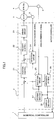
- FIG. 1 shows an example of a motor controller 2 for controlling a spindle motor 3 of a machine tool under control of a numerical controller 1 as a host controller.
- a motor controller 2 comprises a position control section 21, a velocity control section 22, a driving circuit 23, detecting circuits 24 and 25, an arithmetic section 26, a storing section 27 and a display section 28 having a display device such as a LED display and a 7-segmented display.
- the display section 28 may be provided out of the motor controller 2 to be connected with the motor controller.
- An encoder 5 provided at an output shaft of the motor 3 and an encoder 6 provided at a spindle 4 respectively output analog signals of A-phase and B-phase having a phase difference of 90° in the form of sine waves to the detecting circuits 24 and 25 as velocity and position feedback signals.
- the detecting circuit 24 performs an A/D conversion of the analog feedback signal from the encoder 5 and a compensation of the signal using amplitude ratio and phase difference compensation parameters, to feed back the compensated signal to the velocity control section 22 as a velocity feedback digital signal.
- the detecting circuit 25 performs an A/D conversion of the analog feedback signal from the encoder 6 and a compensation using amplitude ratio and phase difference compensation parameters, to feed back the compensated signal to the position control section 21 as a position feedback digital signal.
- the position control section 21 of the motor controller 2 When a motion command is issued from the numerical controller 1 to the motor controller 2, the position control section 21 of the motor controller 2 performs a position feedback control based on the motion command from the numerical controller 1 and the position feedback digital signal from the detecting circuit 25 to obtain a velocity command and outputs the obtained velocity command to the velocity control section 22.
- the velocity control section 22 performs a velocity feedback control based on the velocity command from the position control section 21 and the velocity feedback digital signal from the detecting circuit 24 to obtain a torque command and outputs the obtained torque command to the driving circuit 23 to drivingly control the motor 3.
- Functions of the control sections, etc. other than the driving circuit 23 in the motor controller 2 are realized by software processing performed by a processor of the motor controller 2.
- the arithmetic section 26 and the display section 28 are provided in the motor controller 2 according to the present invention.
- offsets, an amplitude ratio, a phase difference of the analog feedback signals and compensation parameters are automatically obtained by the arithmetic section 26 and the obtained compensation parameters are written to be updated in the storing section 27. Further, the obtained offsets, amplitude ratio and phase difference are displayed by the display section 28 of the motor controller 2 on the display device such as 7-segmented LED display of the motor controller 2 and/or displayed on a display device provided in the numerical controller 1.
- FIG. 2 shows an example of analog feedback signals fed back from the encoders 5 and 6.
- the analog feedback signals are in the form of sine waves of A phase and B phase having a phase difference of (90°+ ⁇ ).
- the B-phase feedback signal g( ⁇ ) is expressed as:
- f( ⁇ ) and g( ⁇ ) are simply referred to as “f” and "g”.
- F( ⁇ ) and G( ⁇ ) are simply referred to as “F” and "G”, respectively.
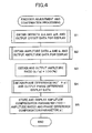
- the processor of the motor controller After switching an operation mode of the numerical controller 1 to an encoder adjusting/confirmation mode and drive of the spindle is started, the processor of the motor controller starts the processing as shown in FIG. 4.
- the offset data ⁇ A and ⁇ B of A-phase and B-phase are obtained based on the digital feedback signals after being subjected to A/D conversion by the detecting circuits 24 and 25.
- Each of the obtained offset data ⁇ A and ⁇ B are divided by an amplification of the A/D conversion to obtain respective display data in the unit of mV, and displayed by the display section'28 and/or a display device of the numerical controller 1 (Step S1).
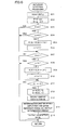
- FIG. 5 An example of processing for obtaining the offset data is shown in FIG. 5.
- the processor executes this processing at every predetermined period.
- FIG. 5 only the processing for obtaining the offset data of A-phase is shown and the offset data of B-phase are obtained in the same manner.
- Step 101 the A-phase feedback signal f converted into digital signal is read (Step 101). It is determined whether or not a value stored in a register R(f) for storing the feedback signal data of A-phase is "0" (Step 102).
- the register R(f), registers Amax and Amin, and registers for storing indexes i and j are all set to "0" in an initial setting when the encoder adjusting/confirming processing is started.
- a determination result in Step 102 is initially "YES” and the procedure proceeds to Step 111 where the feedback signal data f read in Step 101 is stored. It is determined whether or not the indexes i and j are of a set value C (Step 112). Since the indexes 1 and j are initially set to "0", the procedure in this processing period terminates.
- Step 104 the procedure proceeds from Step 102 to Step 103 to obtain a sign of a difference obtained by subtracting the value of the register R(f) from the data f read at Step 101. It is determined whether the sign is changed or not by comparing the obtained sign and the sign stored in a register for storing the sign (Step 104). If the register stores no sign, i.e. stores "0", it is deemed that the sign is not changed irrespective of the obtained sign of "+” or "-".
- Step 110 the procedure proceeds to Step 110 where the sign obtained in Step 103 is stored in the register and then the data f read in Step 101 is stored in the register R(f) (Step 111). Then, it is determined whether or not the indexes i and j are of the set value C (Step 112) and if the indexes are not of the set value C, the procedure of this processing period terminates. Subsequently, the abovementioned processing is repeatedly executed at every processing period and when it is determined that the sign is changed at Step 104, it is determined whether or not the sign is changed from "+" to "-” or "0". Although it is unlikely that the sign obtained in Step 103 is "0", the sign might be "0" in dependence of resolution of the A/D converter and thus the determination in this step includes the case of the change of the sign from "+” to "0".
- the sign of the difference becomes "-".
- Step 104 When it is determined that the sign has changed in Step 104 and the determination result in Step 105 is "NO", i.e., the sign has changed from "-" to "+” or "0", it is determined that the value stored in the register R(f) is a local minimum and an absolute value thereof is added to the value of the register Amin (Step 108). Then, the index j is incrementally increased by "1" (Step 109) and the procedure proceeds to Step 110.
- the abovementioned processing is repeatedly executed until both of the indexes i and j reach the set value C.
- the register Amax stores the sum of the local maximums of the number of times C
- the register Amin stores the sum of the local minimum of the number of times C.
- a offset value ⁇ A is obtained by adding the obtained amplitude to the average value of the local minimums.
- offset data ⁇ A of A-phase is multiplied by a conversion coefficient k in the conversion from the digital signal value to the analog signal value (mV) to obtain display data for A-phase offset.
- the obtained data is displayed by the display section 28 and/or sent to the numerical controller 1 to be displayed by the display device of the numerical controller 1 (Step 114).
- a reference value V0 (2.5V in the example of FIG. 2) is subtracted from the analog offset value to obtain an offset value ⁇ A from the reference value V0, and it is determined whether or not the offset value ⁇ A is within a reference range (Step 115).
- An indication that the offset value ⁇ A is within the reference range or not is displayed by the display section 28 (Step 116 or 117). For example, an indication of "O" is displayed at a section for displaying an offset status of A-phase on a display device of the display section 28 if the offset value ⁇ A is not within the reference range, and no indication is displayed at that section if the offset value ⁇ A is within the reference range.
- a signal indicating completion of detection of the A-phase offset is outputted (Step 118) and the processing terminates.
- the similar processing is performed to obtain offset data ⁇ B of B-phase and offset display data of B-phase and the obtained display data are displayed by the display section 28 and/or the display device of the numerical controller 1. Further, an indication that the offset value ⁇ B is within the reference range or not is displayed.
- the offset data ⁇ A and ⁇ B of A-phase and B-phase are obtained and the offset display data of A-phase and B-phase are displayed.
- the procedure proceeds to Step S2 in which amplitude data "a" of A-phase and amplitude data "b" of B-phase are obtained.
- the amplitude data "a” and “b” may be obtained by adopting the value of " ⁇ (Amax/C) - (Amin/C) ⁇ /2" obtained in Step 113. In this embodiment, however, the amplitude data "a” and “b” are obtained based on the feedback signal data after canceling the offsets in order to obtain more precise data.
- phase difference ⁇ is generally of a small value
- the other of the A/D converted values is of a positive or negative maximum value.
- amplitudes "a” and "b” are multiplied by the conversion coefficient k, which is determined by amplification of the A/D conversion to the analog value (mV), to obtain the amplitude display data and the obtained amplitude display data are displayed by the display section 28 and/or by the display device of the numerical controller 1.
- FIG. 6 is a flowchart of the processing of obtaining the amplitude data to be executed by the processor of the motor controller 2 at every processing period.
- the digital feedback signals f and g of A-phase and B-phase, respectively, are read (Step 201).
- the offset data ⁇ A and ⁇ B obtained in Step S1 are subtracted from the read signals f and g, respectively, to obtain digital feedback signal data F and G with the offset canceled (Step 202).
- indexes m and n do not reach the set value C, the procedure of the present processing period is terminated.
- the indexes m and n, and registers R(G) and R(F) as described later are all set to "0" at the initial setting.
- Step 204 it is determined whether or not the index m reaches the set value C. If the index m does not reach the set value C, an absolute value of the B-phase digital feedback signal data G obtained in Step 202 is added to the register R(G) (Step 205). Then, the index m is incrementally increased by "1" (Step 206) and the procedure proceeds to Step 207.
- Step 208 it is determined whether or not the index n reaches the set value C (Step 208). If the index n does not reach the set value C, an absolute value of the A-phase digital feedback signal data F obtained in Step 202 is added to the register R(F) (Step 209). Then, the index n is incrementally increased by "1" (Step 210) and the procedure proceeds to Step 211.
- Step 204 to Step 206 when it is determined that the A-phase digital feedback signal data F is substantially "0", the processing from Step 204 to Step 206 is performed and when it is determined that the B-phase digital feedback signal data G is substantially "0", the processing from Step 208 to Step 210 is performed. Then, when both of the indexes m and n reach the set value C, i.e., the digital feedback signals G and F when the data of the other phase is substantially "0" have been added to the values of the registers R(G) and R(F), respectively, by C times, the procedure proceeds from Step 211 to Step 212.
- Step 212 the value stored in the register R(F) is divided the set value C to obtain an average value of absolute values of the positive or negative maximums of A-phase as the amplitude "a" of A-phase.
- the value stored in the register R(G) is divided the set value C to obtain an average value of absolute values of the positive or negative maximums of B-phase as the amplitude "b" of B-phase.
- the obtained amplitudes "a” and “b” are multiplied by the conversion coefficient k, which is determined by amplification of the A/D conversion to the analog value (mV), to obtain the amplitude display data and the obtained amplitude display data are displayed by the display section 28 and/or the display device of the numerical controller 1 (Step 213). It is determined whether or not the amplitudes "a” and “b” (mV) are within the reference range (Step 214) and the determination results for respective phases A and B are displayed on the display section 28 and/or the display device of the numerical controller 1.
- Step 215 a signal indicating a completion of the amplitude data detection processing is outputted (Step 215) and the amplitude data detection processing of Step S2 is terminated.
- the above amplitude ratio is sent to the display section 28 and/or the numerical controller 1 to be displayed by the display section 28 and/or the display device of the numerical controller 1 (Step S3).
- Step S4 the phase difference of the feedback signals of A-phase and B-phase is obtained.
- a principle of obtaining an error ⁇ of the phase difference will be described.
- the error ⁇ of the phase difference is obtained according to the equation (10). Since the amplitudes "a" and "b" are already obtained in Step S2, the error ⁇ is determined by determining values of R1 and R2.
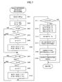
- FIG. 7 shows processing for obtaining the error ⁇ of the phase difference to be performed by the processor of the motor controller 2 at every predetermined processing period.
- the feedback signal data f and g of A-phase and B-phase, respectively, are read (Step 301).
- Step 307 If the determination result in Step 307 is "NO”, it is determined whether or not indexes p and q reach a set value C (Step 311). If the indexes p and q does not reach the set value C, the procedure in the present processing period terminates.
- the indexes p and q, registers R(F), R(G), Q(F) and Q(G) are all set to "0" at the initial setting.
- Step 311 it is determined whether or not both of the indexes p and q reach the set value C and if both of the indexes p and q do not reach the set value C, the processing of the present processing period is terminated.
- the above processing is repeatedly executed until both of the indexes p and q reach the set value C, so that the absolute values of the A-phase and B-phase feedback data F and G when the feedback data F and G are equal to each other, are added to the register R(F) and R(G), respectively, by C times. Also, the absolute values of the A-phase and B-phase feedback data F and G when the feedback data F and G have the same absolute value and different signs are added to the register Q(F) and Q(G), respectively, by C times.
- R1 in the equation (4) is determined based on thus obtained average values F1s and G1s
- R2 [F2s 2 + G2s 2 ] 1/2
- the error ⁇ of the phase difference is determined according to the equation (10) using the obtained R1 and R2 and the amplitude data "a" and "b” obtained in Step S2 (Step 314).
- a 90 degree is added to the error ⁇ of the phase difference and the obtained phase difference (90°+ ⁇ ) is displayed by the display section 28 and/or the data of the phase difference (90°+ ⁇ ) are sent to the numerical controller 1 and displayed by the display device of the numerical controller 1 (Step 315). Then, a signal indicating completion of the phase difference detection is outputted (Step 316) and the phase difference detection processing is terminated.
- a value obtained by subtracting the amplitude ratio obtained in Step S3 from "100" as the parameter for compensating the amplitude ratio, and the error ⁇ of the phase difference obtained in Step 314 as the parameter for compensating the phase difference are stored in the storing section 27.
- the amplitude ratio compensating parameter and the phase difference compensating parameter are displayed by the display section 28 and/or the display device of the numerical controller 1 (Step S5) and the encoder adjustment/confirmation processing is terminated.
- the present invention it is not necessary to observe wave forms of feedback signals inputted to a motor controller from an encoder with a special measuring device such as oscilloscope in adjusting/confirming the analog feedback signals from the encoders, so that a state of the analog feedback signals is easily discriminated. Further, since the special measuring device is unnecessary and acceptability of the analog feedback signals is judged automatically, the adjustment and confirmation of the feedback signals are simplified and facilitated.
Landscapes
- Engineering & Computer Science (AREA)
- Human Computer Interaction (AREA)
- Manufacturing & Machinery (AREA)
- Physics & Mathematics (AREA)
- General Physics & Mathematics (AREA)
- Automation & Control Theory (AREA)
- Control Of Electric Motors In General (AREA)
Abstract
Description




Claims (12)
- A motor controller for performing control of position or velocity of a movable member mechanically connected with a motor using analog feedback signals from encoders for detecting rotational position or velocity of the motor, or position or velocity of the movable member, wherein said motor controller includes means for displaying information on at least one of amplitudes, offsets and a phase difference of the analog feedback signals on a display section of the motor controller or a host controller connected with the motor controller.
- A motor controller according to claim 1, wherein the display section of the motor controller includes a LED display device.
- A motor controller according to claim 1, wherein the display section of the motor controller includes a seven-segment display device.
- A motor controller according to claim 1, wherein the display section of the motor controller includes a display device connected with the motor controller.
- A motor controller according to claim 1, wherein the information on at least one of the amplitudes, the offsets and the phase difference is obtained based on A/D conversion values of the analog feedback signals.
- A motor controller according to claim 1, further including means for calculating at least one of the offsets, the amplitudes and the phase difference of the analog feedback signals of two different phases.
- A motor controller for performing control of position or velocity of a movable member mechanically connected with a motor using analog feedback signals from encoders for detecting rotational position or velocity of the motor, or position or velocity of the movable member, wherein said motor controller includes means for displaying results of comparison of amplitudes and/or offsets of the analog feedback signals with respective predetermined values on a display section of the motor controller or a host controller connected with the motor controller.
- A motor controller according to claim 7, wherein the display section of the motor controller includes a LED display device.
- A motor controller according to claim 7, wherein the display section of the motor controller includes a seven-segment display device.
- A motor controller according to claim 7, wherein the display section of the motor controller includes a display device connected with the motor controller.
- A motor controller according to claim 7, wherein the amplitudes and/or the offsets are obtained based on A/D conversion values of the analog feedback signals.
- A motor controller according to claim 7, further including means for calculating the offsets and/or the amplitudes of the analog feedback signals of two different phases.
Applications Claiming Priority (2)
| Application Number | Priority Date | Filing Date | Title |
|---|---|---|---|
| JP2000391888 | 2000-12-25 | ||
| JP2000391888A JP2002199768A (en) | 2000-12-25 | 2000-12-25 | Motor controller |
Publications (3)
| Publication Number | Publication Date |
|---|---|
| EP1220070A2 true EP1220070A2 (en) | 2002-07-03 |
| EP1220070A3 EP1220070A3 (en) | 2004-04-28 |
| EP1220070B1 EP1220070B1 (en) | 2007-08-29 |
Family
ID=18857965
Family Applications (1)
| Application Number | Title | Priority Date | Filing Date |
|---|---|---|---|
| EP01310675A Expired - Lifetime EP1220070B1 (en) | 2000-12-25 | 2001-12-20 | Motor controller with information display |
Country Status (4)
| Country | Link |
|---|---|
| US (1) | US6822414B2 (en) |
| EP (1) | EP1220070B1 (en) |
| JP (1) | JP2002199768A (en) |
| DE (1) | DE60130190T2 (en) |
Families Citing this family (6)
| Publication number | Priority date | Publication date | Assignee | Title |
|---|---|---|---|---|
| US7944165B1 (en) | 2008-05-02 | 2011-05-17 | Wd Media, Inc. | Inspection system with dual encoders |
| JP5355029B2 (en) * | 2008-10-20 | 2013-11-27 | キヤノン株式会社 | Drive device |
| FR2960357B1 (en) * | 2010-05-21 | 2012-06-29 | Soc Tech Michelin | METHOD FOR AUTOMATICALLY ADJUSTING A RESOLVER OF AN ELECTRIC MACHINE |
| JP6200186B2 (en) | 2013-04-03 | 2017-09-20 | キヤノン株式会社 | Image processing apparatus and correction method for image processing apparatus |
| JP6490142B2 (en) | 2017-05-18 | 2019-03-27 | ファナック株式会社 | Motor drive device |
| JP6464224B2 (en) | 2017-05-18 | 2019-02-06 | ファナック株式会社 | Motor drive device |
Family Cites Families (19)
| Publication number | Priority date | Publication date | Assignee | Title |
|---|---|---|---|---|
| US3358201A (en) * | 1966-07-27 | 1967-12-12 | Giddings & Lewis | Apparatus for compensating machine feed driveservomechanisms |
| US3676765A (en) * | 1970-06-30 | 1972-07-11 | Trans Sonics Inc | Tachometer generator |
| US3800898A (en) * | 1972-05-17 | 1974-04-02 | D Griffin | Electrically powered bicycle |
| US3898563A (en) * | 1973-11-15 | 1975-08-05 | David E Erisman | Solid state bicycle speedometer, tachometer, and odometer device |
| US4074177A (en) * | 1975-07-17 | 1978-02-14 | Giddings & Lewis, Inc. | Methods and apparatus for automatic movement of a member to precisely indexed positions despite signal drift or offset |
| US4157658A (en) * | 1978-01-17 | 1979-06-12 | Fiber Controls Corporation | Engine horsepower measurement system |
| DE2805989C2 (en) * | 1978-02-13 | 1986-11-06 | Sartorius GmbH, 3400 Göttingen | Automatic control for the switching motor of electromechanical, self-importing scales |
| US4224515A (en) * | 1978-10-27 | 1980-09-23 | The United States Of America As Represented By The Secretary Of The Air Force | High accuracy optical shaft encoder system |
| US4358723A (en) * | 1980-08-29 | 1982-11-09 | Scholl Jule A | Method and apparatus for measuring the rotation of a work table |
| US4341995A (en) * | 1981-05-29 | 1982-07-27 | American Optical Corporation | Velocity profile analyzer |
| US4527101A (en) * | 1983-11-23 | 1985-07-02 | Black & Decker Inc. | Universal electric motor speed sensing by using Fourier transform method |
| US4878002A (en) * | 1988-10-27 | 1989-10-31 | Advanced Engineering Systems, Operations & Products, Inc. | Multi-axis DSP-based parallel processing servo controller for machine tools and robots |
| US4954763A (en) * | 1989-01-31 | 1990-09-04 | Micro Fast Controls, Inc. | Resolver analog to digital input module for use in a programmable controller system |
| US5811946A (en) * | 1992-03-16 | 1998-09-22 | Lockheed Martin Corporation | System and method for velocity control of a D.C. Motor |
| JP3178202B2 (en) | 1992-12-10 | 2001-06-18 | 松下電器産業株式会社 | Servo motor control parameter adjustment device and adjustment method |
| US5646496A (en) * | 1994-11-08 | 1997-07-08 | Dana Corporation | Apparatus and method for generating digital position signals for a rotatable shaft |
| US5978742A (en) * | 1997-04-04 | 1999-11-02 | Tektronix, Inc. | Method and apparatus for digital sampling of electrical waveforms |
| JPH11332273A (en) | 1998-05-15 | 1999-11-30 | Teikoku Electric Mfg Co Ltd | Operation monitoring apparatus for canned motor |
| JP2000341985A (en) | 1999-05-27 | 2000-12-08 | Hitachi Ltd | Motor control device with failure diagnosis function |
-
2000
- 2000-12-25 JP JP2000391888A patent/JP2002199768A/en active Pending
-
2001
- 2001-12-20 EP EP01310675A patent/EP1220070B1/en not_active Expired - Lifetime
- 2001-12-20 DE DE60130190T patent/DE60130190T2/en not_active Expired - Lifetime
- 2001-12-20 US US10/022,385 patent/US6822414B2/en not_active Expired - Lifetime
Also Published As
| Publication number | Publication date |
|---|---|
| US20020113571A1 (en) | 2002-08-22 |
| EP1220070B1 (en) | 2007-08-29 |
| JP2002199768A (en) | 2002-07-12 |
| EP1220070A3 (en) | 2004-04-28 |
| DE60130190D1 (en) | 2007-10-11 |
| DE60130190T2 (en) | 2008-05-21 |
| US6822414B2 (en) | 2004-11-23 |
Similar Documents
| Publication | Publication Date | Title |
|---|---|---|
| JP3792718B2 (en) | Angle measurement method for rotating body | |
| JP2515891B2 (en) | Angle sensor, torque sensor, and electric power steering device controlled according to the outputs of the sensors | |
| US6618688B2 (en) | Apparatus and method for determining absolute position with steering path and steering angle sensors | |
| US5525885A (en) | Position detecting apparatus and position compensating method therefor | |
| US6624608B2 (en) | Indicating instrument for a vehicle | |
| JP2004177154A (en) | Rotation angle detector | |
| JP4260544B2 (en) | Rotation angle detection device and rotation control device | |
| EP1220070B1 (en) | Motor controller with information display | |
| US6563443B2 (en) | Method and device for absolute position determination | |
| US7034495B2 (en) | Indicating instrument | |
| US5095630A (en) | Electronic magnetic compass | |
| US6697680B2 (en) | Method for compensating signals from an absolute angular position sensor assembly | |
| US6481274B2 (en) | Position sensor setting and testing method | |
| JPH037968B2 (en) | ||
| JPH06109565A (en) | Motor cogging torque measuring device and measuring method | |
| US7254470B2 (en) | Fault tolerant torque sensor signal processing | |
| EP0588403B1 (en) | Method and apparatus for driving a gauge | |
| US20010030283A1 (en) | Position measuring device and method for operation of a position measuring device | |
| EP1467183A2 (en) | Rotational angle detecting apparatus and torque detecting apparatus | |
| JPH11110045A (en) | Stepping motor control device and control device for lens drive system of video camera using stepping motor | |
| JP2002524754A (en) | Precision position encoder with coarse position indicator | |
| US5635622A (en) | Method of compensating for gauge hysteresis | |
| JP3610707B2 (en) | Magnetic measuring instrument | |
| EP0412825B1 (en) | Signal compensator | |
| EP0474362A2 (en) | Angular velocity sensing apparatus |
Legal Events
| Date | Code | Title | Description |
|---|---|---|---|
| PUAI | Public reference made under article 153(3) epc to a published international application that has entered the european phase |
Free format text: ORIGINAL CODE: 0009012 |
|
| AK | Designated contracting states |
Kind code of ref document: A2 Designated state(s): AT BE CH CY DE DK ES FI FR GB GR IE IT LI LU MC NL PT SE TR |
|
| AX | Request for extension of the european patent |
Free format text: AL;LT;LV;MK;RO;SI |
|
| PUAL | Search report despatched |
Free format text: ORIGINAL CODE: 0009013 |
|
| AK | Designated contracting states |
Kind code of ref document: A3 Designated state(s): AT BE CH CY DE DK ES FI FR GB GR IE IT LI LU MC NL PT SE TR |
|
| AX | Request for extension of the european patent |
Extension state: AL LT LV MK RO SI |
|
| 17P | Request for examination filed |
Effective date: 20040823 |
|
| AKX | Designation fees paid |
Designated state(s): DE |
|
| GRAP | Despatch of communication of intention to grant a patent |
Free format text: ORIGINAL CODE: EPIDOSNIGR1 |
|
| GRAS | Grant fee paid |
Free format text: ORIGINAL CODE: EPIDOSNIGR3 |
|
| GRAA | (expected) grant |
Free format text: ORIGINAL CODE: 0009210 |
|
| AK | Designated contracting states |
Kind code of ref document: B1 Designated state(s): DE |
|
| REF | Corresponds to: |
Ref document number: 60130190 Country of ref document: DE Date of ref document: 20071011 Kind code of ref document: P |
|
| PLBE | No opposition filed within time limit |
Free format text: ORIGINAL CODE: 0009261 |
|
| STAA | Information on the status of an ep patent application or granted ep patent |
Free format text: STATUS: NO OPPOSITION FILED WITHIN TIME LIMIT |
|
| 26N | No opposition filed |
Effective date: 20080530 |
|
| REG | Reference to a national code |
Ref country code: DE Ref legal event code: R082 Ref document number: 60130190 Country of ref document: DE Representative=s name: HASELTINE LAKE LLP, DE |
|
| PGFP | Annual fee paid to national office [announced via postgrant information from national office to epo] |
Ref country code: DE Payment date: 20191210 Year of fee payment: 19 |
|
| REG | Reference to a national code |
Ref country code: DE Ref legal event code: R082 Ref document number: 60130190 Country of ref document: DE Representative=s name: HL KEMPNER PATENTANWALT, RECHTSANWALT, SOLICIT, DE |
|
| REG | Reference to a national code |
Ref country code: DE Ref legal event code: R119 Ref document number: 60130190 Country of ref document: DE |
|
| PG25 | Lapsed in a contracting state [announced via postgrant information from national office to epo] |
Ref country code: DE Free format text: LAPSE BECAUSE OF NON-PAYMENT OF DUE FEES Effective date: 20210701 |