EP1220064A2 - Disturbance estimated type control system, gas compressor control system and method of designing a disturbance estimated type control system - Google Patents
Disturbance estimated type control system, gas compressor control system and method of designing a disturbance estimated type control system Download PDFInfo
- Publication number
- EP1220064A2 EP1220064A2 EP01310802A EP01310802A EP1220064A2 EP 1220064 A2 EP1220064 A2 EP 1220064A2 EP 01310802 A EP01310802 A EP 01310802A EP 01310802 A EP01310802 A EP 01310802A EP 1220064 A2 EP1220064 A2 EP 1220064A2
- Authority
- EP
- European Patent Office
- Prior art keywords
- disturbance
- control
- signal
- control system
- control object
- Prior art date
- Legal status (The legal status is an assumption and is not a legal conclusion. Google has not performed a legal analysis and makes no representation as to the accuracy of the status listed.)
- Granted
Links
Images






Classifications
-
- G—PHYSICS
- G05—CONTROLLING; REGULATING
- G05B—CONTROL OR REGULATING SYSTEMS IN GENERAL; FUNCTIONAL ELEMENTS OF SUCH SYSTEMS; MONITORING OR TESTING ARRANGEMENTS FOR SUCH SYSTEMS OR ELEMENTS
- G05B13/00—Adaptive control systems, i.e. systems automatically adjusting themselves to have a performance which is optimum according to some preassigned criterion
- G05B13/02—Adaptive control systems, i.e. systems automatically adjusting themselves to have a performance which is optimum according to some preassigned criterion electric
- G05B13/04—Adaptive control systems, i.e. systems automatically adjusting themselves to have a performance which is optimum according to some preassigned criterion electric involving the use of models or simulators
-
- G—PHYSICS
- G05—CONTROLLING; REGULATING
- G05B—CONTROL OR REGULATING SYSTEMS IN GENERAL; FUNCTIONAL ELEMENTS OF SUCH SYSTEMS; MONITORING OR TESTING ARRANGEMENTS FOR SUCH SYSTEMS OR ELEMENTS
- G05B5/00—Anti-hunting arrangements
- G05B5/01—Anti-hunting arrangements electric
-
- F—MECHANICAL ENGINEERING; LIGHTING; HEATING; WEAPONS; BLASTING
- F04—POSITIVE - DISPLACEMENT MACHINES FOR LIQUIDS; PUMPS FOR LIQUIDS OR ELASTIC FLUIDS
- F04C—ROTARY-PISTON, OR OSCILLATING-PISTON, POSITIVE-DISPLACEMENT MACHINES FOR LIQUIDS; ROTARY-PISTON, OR OSCILLATING-PISTON, POSITIVE-DISPLACEMENT PUMPS
- F04C18/00—Rotary-piston pumps specially adapted for elastic fluids
- F04C18/30—Rotary-piston pumps specially adapted for elastic fluids having the characteristics covered by two or more of groups F04C18/02, F04C18/08, F04C18/22, F04C18/24, F04C18/48, or having the characteristics covered by one of these groups together with some other type of movement between co-operating members
- F04C18/34—Rotary-piston pumps specially adapted for elastic fluids having the characteristics covered by two or more of groups F04C18/02, F04C18/08, F04C18/22, F04C18/24, F04C18/48, or having the characteristics covered by one of these groups together with some other type of movement between co-operating members having the movement defined in group F04C18/08 or F04C18/22 and relative reciprocation between the co-operating members
- F04C18/344—Rotary-piston pumps specially adapted for elastic fluids having the characteristics covered by two or more of groups F04C18/02, F04C18/08, F04C18/22, F04C18/24, F04C18/48, or having the characteristics covered by one of these groups together with some other type of movement between co-operating members having the movement defined in group F04C18/08 or F04C18/22 and relative reciprocation between the co-operating members with vanes reciprocating with respect to the inner member
- F04C18/3446—Rotary-piston pumps specially adapted for elastic fluids having the characteristics covered by two or more of groups F04C18/02, F04C18/08, F04C18/22, F04C18/24, F04C18/48, or having the characteristics covered by one of these groups together with some other type of movement between co-operating members having the movement defined in group F04C18/08 or F04C18/22 and relative reciprocation between the co-operating members with vanes reciprocating with respect to the inner member the inner and outer member being in contact along more than one line or surface
Definitions
- the present invention concerns a disturbance estimated type control system, a gas compressor control system and a method of designing a disturbance estimated type control system and, in particular, relates to a disturbance estimated type control system and a gas compressor control system that are insensitive to parameter variations such as a heat load variation and a rotating speed change and a method of designing a disturbance estimated type control system.
- Displacement control of a refrigeration air conditioning system for a car air conditioner is for observing an air temperature at an outlet of an evaporator or a room temperature by a temperature sensor and changing a displacement of a gas compressor such that the observed temperature coincides with a target temperature set in advance.
- the displacement of the gas compressor is changed such that a refrigerant suction pressure of the gas compressor becomes a desired pressure value.
- displacement control is performed using rotating speed information of a gas compressor together with air temperature information.
- FIG. 12 An overall schematic configuration view of the air conditioning system is shown in Fig. 12.
- the air conditioning system is mounted, for example, on a car.
- an evaporator 51 is a heat exchanger involving ventilation by a fan 52 and cools air in a cabin.
- Refrigerant gas that is evaporated within the evaporator 51 is taken into a variable displacement type gas compressor 10 and pressurized to be sent to a condenser 53.
- the refrigerant gas is liquidized and heat absorbed from the inside of the cabin is discharged to the outside of the car.
- An expansion valve 54 is made to rapidly decrease a pressure of the refrigerant gas from a high pressure to a low pressure.
- a rotating shaft 11 of the variable displacement type gas compressor 10 is made such that a shaft power of an engine 59 is transmitted to it and it is rotationally driven.
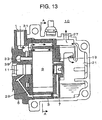
- FIG. 13 A sectional view of the variable displacement type gas compressor 10 is shown in Fig. 13 and a sectional view cut along line A-A and viewed in the direction of arrows A in Fig. 13 of the variable displacement type gas compressor 10 is shown in Fig. 14.
- a suction port 1 of the variable displacement type gas compressor 10 is made to suction refrigerant gas from the evaporator 51 connected to the outside.
- a cylinder 3 is clamped between a front head 5 and a rear side block 7.
- a rotor 9 is rotatably arranged within the cylinder 3.
- the rotor 9 is penetrated by and fixed to a rotary shaft 11.
- Bane grooves 13 are formed in the radial direction on the external circumference of the rotor 9 and banes 15 are slidably inserted in the bane grooves 13. Then, the banes 15 are biased to the internal wall of the cylinder 3 by a centrifugal force and an oil pressure of the bottoms of the bane grooves 13 when the rotor 9 is rotating.
- the inside of the cylinder 3 is partitioned into a plurality of small chambers by the rotor 9 and the banes 15. These small chambers are referred to as compressing chambers 17, which repeat increasing and decreasing changes of a displacement by the rotation of the rotor 9.
- High-pressure refrigerant gas compressed in the compressing chamber 17 is sent to the discharge chamber 21 via a discharge port 23 and a discharge valve 25. Then, the refrigerant gas is sent to the condenser 53 in the outside from the discharge chamber 21 via the discharge port 27.
- This variable displacement type gas compressor 10 is provided with a displacement varying mechanism 30.
- This displacement varying mechanism 30 is made such that it can variably adjust a discharge capacity of refrigerant gas according to a temperature in a cabin.
- An example of a configuration of the displacement varying mechanism 30 is shown in Fig. 15.
- a control plate 29 is arranged in the front head 5 to face the side portion of the cylinder 3. Notches 29a are provided in two parts of the control plate 29. These notches 29a cause the inside of the cylinder 3 and a suction chamber 31 leading to the suction port 1 to communicate with each other. On the other hand, the compressing chambers 17 are formed in spaces closed by the part on the control plate 29 where there is no notch, the internal wall of the cylinder 3 and the banes 15.
- the rotation of the control plate 29 is performed by a driving shaft 39 of hydraulic drive via a pin 33. Oil is injected into a sleeve 35 from the discharge chamber 21 by adjusting the opening degree of a control valve 37 and the driving shaft 39 is moved straight by oil pressure at this point. Then, this straight movement is converted into rotating movement via the pin 33 to cause the control plate 29 to rotate.
- An injection amount of oil can be changed by altering the opening degree of the control valve 37. This alteration of the ' opening degree is performed by changing a displacement control command value (duty ratio) shown in Fig. 16.
- the control plate 29 is rotated under the balance with an elastic force by a spring 38 in accordance with a differential pressure between a control pressure Pc in the sleeve 35 and a pressure Ps in the suction chamber 31.
- a temperature sensor 55 is disposed in order to detect an air temperature at the outlet of the evaporator 51.
- a rotating speed sensor 57 is disposed in order to detect a rotating speed of the engine 59.
- a displacement control command value is calculated in a control circuit 61 based on a detected signal of this temperature sensor 55 and a rotating speed of the engine 59.
- This displacement control command value is signal-amplified by a displacement control signal generating circuit 65 and, then, transmitted to the control valve 37 of the displacement varying mechanism 30.
- step 1 a target refrigerant flow rate of the variable displacement type gas compressor 10 is calculated based on a temperature deviation between a target temperature and a detected temperature. The calculation in this case is performed by PID control or the like.
- step 3 a rotating speed of the variable displacement type gas compressor 10 is calculated from this calculated target refrigerant flow rate or a discharge capacity of the variable displacement type gas compressor 10 is calculated taking a rotating speed of the engine 59 into account.
- step 5 a rotating speed correcting calculation is performed from this discharge capacity based on a not-shown property curve showing a relation between a discharge capacity and a displacement control command value and a displacement control command value by which an opening degree of the control valve 37 should be adjusted is determined.
- the displacement control command value at this point is commanded to be small. As a result, an average current falls in step 7 and the opening degree of the control valve 37 is reduced in step 9.
- step 11 the control pressure Pc inside the sleeve 35 falls in step 11.
- the driving shaft 39 is moved downward in step 13 and the control plate 29 rotates to the right in step 15.
- the discharge capacity of the variable displacement type gas compressor 10 becomes small in step 17 and the cooling capability falls.
- the present invention has been devised in view of such conventional problems and it is an object of the present invention to provide a disturbance estimated type control system and a gas compressor control system that are insensitive to parameter variations such as a heat load variation and a rotating speed change and a method of designing a disturbance estimated type control system.
- a disturbance estimated type control system comprising: a control object; disturbance estimating means for estimating a disturbance added to an input of the control object based on an input signal to be inputted in the control object and a detection signal detected from the control object; compensating means for compensating for the detection signal and outputting a control signal; and calculating means for subtracting a disturbance estimated by the disturbance estimating means from the control signal and considering a subtraction result as the input signal, characterized in that a mathematical model (nominal model) of the control object comprising of a state equation and a transfer function is prepared by system identification based on an experiment, the compensating means is designed from the mathematical model (nominal model), and the disturbance estimating means is prepared from an expanded state equation (expansion system) comprising of a mathematical model (expansion model) taking a disturbance into account with respect to the mathematical model (nominal model).
- a nominal model of a system is prepared utilizing a system identification technology. Then, disturbance estimating means is prepared from am expanded state equation (expansion system) comprising of mathematical model (expansion model) taking a disturbance into account with respect to this mathematical model (nominal model).
- a disturbance against a control object can be offset by subtracting a disturbance estimated by the disturbance estimating means from a control signal that is an output of compensating means.
- the present invention is configured by comprising: a variable displacement type gas compressor having displacement altering means that is capable of altering a displacement within a compressing chamber; an input signal to be inputted in the displacement altering means; a detection signal in which at least one piece of information among an air temperature in a room, an air temperature at an outlet of an evaporator, a refrigerant flow, a refrigerant pressure on a suction side of a gas compressor and the like is detected; disturbance estimating means for estimating a disturbance of the variable displacement type gas compressor based on the detection signal and the input signal; compensating means for compensating for the detection signal to output a control signal; and calculating means for subtracting a disturbance estimated by the disturbance estimating means from the control signal to consider a subtraction result the input signal.
- a disturbance is, for example, a variation of a fan ventilating an evaporator, a variation of the number of rotations of a variable displacement type gas compressor that is driven by an engine, or the like.
- a refrigeration air conditioning system control system which is insensitive to a parameter variation caused by the change in physical property values of air and refrigerant due to a heat load variation and the change in refrigerant flow due to a variation of the number of rotations, can be realized with fixed compensating means having a simple structure.
- a method of designing a disturbance estimated type control system that comprises: a control object; disturbance estimating means for estimating a disturbance added to an input of the control object based on an input signal to be inputted in the control object and a detection signal detected from the control object; compensating means for compensating for the detection signal and outputting a control signal; and calculating means for subtracting a disturbance estimated by the disturbance estimating means from the control signal and considering a subtraction result as the input signal, characterized by comprising: preparing a mathematical model (nominal model) of the control object comprising of a state equation and a transfer function by system identification; preparing an expanded state equation (expansion system) comprising of the mathematical model and a mathematical model of a disturbance; designing the disturbance estimating means from the state equation (expansion system); and designing the compensating means from the mathematical model (nominal model).
- the present invention is characterized by comprising: determining whether or not the state equation (expansion system) is observable; and if it is determined to be unobservable, compulsorily adding an error of 10% or less to a coefficient corresponding to an A matrix and/or a C matrix of the state equation (expansion system) or a zero-th dimension term of a transfer function numerator and preparing an expansion system including the error, thereby establishing observability.
- the disturbance estimating means and the compensating means can be designed even if the state equation (expansion system) is unobservable.
- the present invention is for applying a disturbance observer whose effectiveness is confirmed in a mechanical system such as a robot and a machine tool (see Kohei Ohnishi, Kiyoshi Ohishi, Kunio Miyaji: "A control method of a separate excitation DC machine using a state observer", the Institute of Electrical Engineers of Japan Thesis Magazine B104-6, pp. 373-379, 1984) to displacement control of a refrigeration air conditioning system.
- the system identification technology is utilized to prepare a nominal model of a refrigeration air conditioning system, an expansion system comprising of the nominal model and a newly assumed disturbance is configured and, after confirming conditions for the expansion system to meet observability that is a configuration condition of an observer, a new disturbance observer is designed to make it possible to mount it on an actual machine.
- a mathematical model is not limited to its mathematical model. Here, it refers to a model that is found according to one average condition.
- the input u is a driving input signal of an actuator for causing a displacement of a variable displacement type gas compressor to change and is a voltage in most cases, but may be variable data or the like that plays the same role inside a computer system for control.
- the output y is a detected value of an air temperature of a part that is to be controlled and is observed in the form of a voltage in most cases, but may be variable data corresponding to the temperature captured into a computer for control.
- the above-described model is a model under a certain condition and does not include a physical parameter variation or a disturbance. This is referred to as a nominal model.
- the system identification per se is a conventional modeling theory and technology (see, for example, Shuichi Adachi: System identification for control by MATLAB, Tokyo Denki University Press, 1996). There are known a prediction error method, a maximum likelihood estimation method, a least-square method, a subspace identification method and the like, and it is assumed that any method may be used but representation is finally made in the form of a state equation.
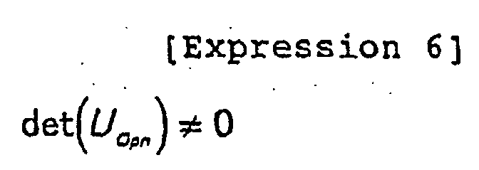
- an identified model is a model that should also have been found by an experiment using input and output, it is controllable and observable (see, for example, Kosato, Mita: Guide to system control theory, Jikkyo Shuppan Co., Ltd., 1979). Conversely, even if there is an uncontrollable or unobservable part in an actual system, modeling is performed with that part neglected.
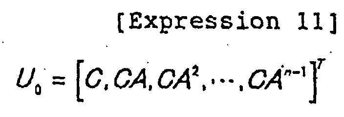
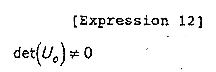
- FIG. 1 A block diagram of an expansion system including a nominal model and a disturbance is shown in Fig. 1. It is known that, if Expressions 7 and 8 are observable, an observer can be designed. A necessary and sufficient condition of observability is that, in the case of a one-output system, a rank of an observable matrix U o (n ⁇ n) of the following Expression 11 is n.
- Expression 15 that is a formula (see Kosato, Mita: Guide to system control theory, Jikkyo Shuppan Co., Ltd., 1979) is utilized, the determinant of Expression 12 can be represented as Expression 16 from Expression 4.
- Expressions 15 and 16 are observable, and thus an observer can be designed.
- a pole increased by preparing an expansion system will be confirmed.
- a formula for a determinant (see Kosato, Mita: Guide to system control theory, Jikkyo shuppan Co., Ltd., 1979) is used, from Expression 7, since the pole of the expression system is s satisfying Expression 18, it is seen that it consists of a pole and the origin of an original nominal model.
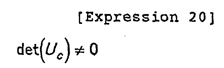
- Expression 20 is uncontrollable.
- the pole of the expansion system consists of a pole and the origin of a nominal system and, moreover, the nominal system is controllable, a pole that causes uncontrollability, that is, an uncontrollable pole is only the origin 0.
- x ⁇ ⁇ R n ⁇ 1 , A ⁇ R n ⁇ n , B ⁇ R n ⁇ 1 , C ⁇ R 1 ⁇ n , K ⁇ R n ⁇ 1 , k pn ⁇ R n pn ⁇ 1 , n n pn + 1 and K is selected such that real parts of all peculiar values of the A-KC matrix of Expression 25 become negative.
- a block diagram of a control object model and an observer is shown in Fig. 2.
- an input u is, for example, a displacement control command value and an output y is a detected temperature of the outlet of the evaporator 51.
- a designing method called a nonsingular form of Gopinath may be used for designing the observer.
- the expansion system Expressions 7 and 8 may be discretized with a zero-th dimension hold as a premise and designed as an identical dimension observer of a digital format or a minimum dimension observer.
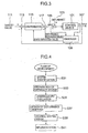
- a block diagram of a control system is shown in Fig. 3.
- a disturbance 103 is applied to a control object 101.
- An input signal 105 e.g., a displacement control command value
- an output signal 107 e.g., a detected temperature at the outlet of the evaporator 51
- a deviation between the output signal 107 and a target value 111 is calculated by a subtractor 113.
- This deviation is subject to compensations such as a state feedback, a servo system of a 1 type and a PID control by a compensator 115 and outputted as a control signal.
- This control signal is subtracted from a disturbance estimated value from the observer 109 by a subtractor 117.
- the disturbance estimated value among estimated values of the observer is fed back to cancel an actual disturbance.
- compensations such as a state feedback, a servo system of a 1 type and a PID control are performed using another state estimated value.
- a nominal model of a refrigeration air conditioning system is prepared utilizing a system identification technology in step 31.
- an expansion system is configured from the nominal model and a disturbance that is assumed anew.
- step 35 it is determined whether or not the expansion system satisfies observability that is a configuration condition of the observer. If it satisfies observability, a new disturbance observer is designed in step 37. This disturbance observer and a compensator are combined in step 39 and mounted on an actual machine in step 41.
- step 35 if the expansion system does not satisfy observability, unobservability is avoided by deliberately adding a deviation to an identification model.
- a constant term of a small value is added to deviate a zero point.
- a refrigeration air conditioning system control system which is insensitive to a parameter variation caused by a change in a physical property value of air and refrigerant due to a heat load variation or a change in a refrigerant flow due to a change in a rotating speed, can be realized with a fixed compensator having a simple structure.
- System identification means preparing some "mathematical model” that can prove that a system is “identical” with an object under a certain “purpose” from a measured value of input and output data of a dynamic system to be an object.
- System identification intended to be performed in the present invention is "system identification for the purpose of control” and several methods have been established.
- a procedure for system identification follows a flow of Fig. 5.
- M sequence data is prepared.
- step 53 implementation in a controller is performed and, in step 55, measurement is performed and the data is stored.
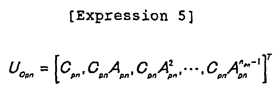
- step 57 an identification program is prepared and, in step 59, identification is executed. More specifically, A pn , B pn and C pn are found.
- step 61 the found A pn , B pn and C pn are evaluated. If an evaluation result is displeasing, the identification program is revised and the identification work is executed again to perform evaluation again. In addition, it becomes necessary to repeatedly perform identification with respect to a control object with significantly changing environmental conditions by changing an amplitude, a cycle and a length of the M sequence data in various ways. Next, preparation of the M sequence data will be described.
- PRBSs Pseudo Random Binary Signals
- M sequence signal Maximum-length linear shift register sequence
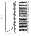
- Fig. 7 shows data strings in which 0 to 10 are command voltages corresponding to a driving current zero to maximum current of the displacement varying mechanism 30 and is an M sequence signal deflected upward and downward by an amplitude 2 with a heat load as a medium load and with an average command value 7.85 at the time when a rotating speed of the variable displacement type gas compressor 10 is 800 rpm as an average value.
- the average value a balanced point of inputs at the time when a target temperature coincides with an air temperature under a condition that a heat load and a rotating speed of the variable displacement type gas compressor 10 are regulated is used. Since the amplitude depends on nonlinear evaluation, increasing and decreasing of the amplitude are attempted in a try and error manner. However, the amplitude of less than zero or more than ten is unacceptable because it causes saturation, the average value is deviated so as to avoid saturation.
- this value may be used as a feed forward value corresponding to a rotating speed.
- 0 to 10 used in the above-described M sequence correspond to the 0 to 1.
- a value at the time of operation at a rotating speed 800 rpm under the environmental conditions of (1) is approximately 0.7, it is sufficient to use 7 that is ten times as large as the value as the average value.
- a balanced point at the time of control may be used.
- the controller outputs an M sequence signal as a voltage. Then, this M sequence signal is given as a control input to the displacement varying mechanism 30 of the variable displacement type gas compressor 10 that is a control object. A resulting air temperature at an outlet of an evaporator is detected in the form of a voltage and captured in the controller.
- a system control system that is insensitive to a parameter variation caused by a change of a physical property value or the like can be realized with a fixed compensator having a simple structure.
Landscapes
- Engineering & Computer Science (AREA)
- Physics & Mathematics (AREA)
- General Physics & Mathematics (AREA)
- Automation & Control Theory (AREA)
- Computer Vision & Pattern Recognition (AREA)
- Artificial Intelligence (AREA)
- Health & Medical Sciences (AREA)
- Evolutionary Computation (AREA)
- Medical Informatics (AREA)
- Software Systems (AREA)
- Feedback Control In General (AREA)
- Rotary Pumps (AREA)
- Applications Or Details Of Rotary Compressors (AREA)
- Control Of Positive-Displacement Pumps (AREA)
Abstract
Description
Here, the input u is a driving input signal of an actuator for causing a displacement of a variable displacement type gas compressor to change and is a voltage in most cases, but may be variable data or the like that plays the same role inside a computer system for control.









Claims (4)
- A disturbance estimated type control system comprising:a control object;disturbance estimating means for estimating a disturbance added to an input of the control object based on an input signal to be inputted in the control object and a detection signal detected from the control object;compensating means for compensating for the detection signal and outputting a control signal; andcalculating means for subtracting a disturbance estimated by the disturbance estimating means from the control signal and considering a subtraction result as the input signal, whereina mathematical model (nominal model) of the control object comprising of a state equation and a transfer function is prepared by system identification based on an experiment,the compensating means is designed from the mathematical model (nominal model), andthe disturbance estimating means is prepared from an expanded state equation (expansion system) comprising of a mathematical model (expansion model) taking a disturbance into account with respect to the mathematical model (nominal model).
- A gas compressor control system comprising:a variable displacement type gas compressor having displacement altering means that is capable of altering a displacement within a compressing chamber;an input signal to be inputted in the displacement altering means;a detection signal in which at least one piece of information among an air temperature in a room, an air temperature at an outlet of an evaporator, a refrigerant flow, a refrigerant pressure on a suction side of a gas compressor and the like is detected;disturbance estimating means for estimating a disturbance of the variable displacement type gas compressor based on the detection signal and the input signal;compensating means for compensating for the detection signal to output a control signal; andcalculating means for subtracting a disturbance estimated by the disturbance estimating means from the control signal to consider a subtraction result the input signal.
- Amethod of designing a disturbance estimated type control system comprising:a control object;disturbance estimating means for estimating a disturbance added to an input of the control object based on an input signal to be inputted in the control object and a detection signal detected from the control object;compensating means for compensating for the detection signal and outputting a control signal; andcalculating means for subtracting a disturbance estimated by the disturbance estimating means from the control signal and considering a subtraction result as the input signal, whereinpreparing a mathematical model (nominal model) of the control object comprising of a state equation and a transfer function by system identification;preparing an expanded state equation (expansion system) comprising of the mathematical model and a mathematical model of a disturbance;designing the disturbance estimating means from the state equation (expansion system); anddesigning the compensating means from the mathematical model (nominal model).
- Amethod of designing a disturbance estimated type control system according to claim 3, whereindetermining whether or not the state equation (expansion system) is observable; andif it is determined to be unobservable, compulsorily adding an error of 10% or less to a coefficient corresponding to an A matrix and/or a C matrix of the state equation (expansion system) or a zero-th dimension term of a transfer function numerator and preparing an expansion system including the error, thereby establishing observability.
Applications Claiming Priority (2)
| Application Number | Priority Date | Filing Date | Title |
|---|---|---|---|
| JP2000401397A JP2002202802A (en) | 2000-12-28 | 2000-12-28 | Disturbance estimation type control system, gas compressor control system, and design method of disturbance estimation type control system |
| JP2000401397 | 2000-12-28 |
Publications (3)
| Publication Number | Publication Date |
|---|---|
| EP1220064A2 true EP1220064A2 (en) | 2002-07-03 |
| EP1220064A3 EP1220064A3 (en) | 2003-05-21 |
| EP1220064B1 EP1220064B1 (en) | 2005-11-09 |
Family
ID=18865835
Family Applications (1)
| Application Number | Title | Priority Date | Filing Date |
|---|---|---|---|
| EP01310802A Expired - Lifetime EP1220064B1 (en) | 2000-12-28 | 2001-12-21 | Disturbance estimated type control system, gas compressor control system and method of designing a disturbance estimated type control system |
Country Status (4)
| Country | Link |
|---|---|
| US (1) | US7142930B2 (en) |
| EP (1) | EP1220064B1 (en) |
| JP (1) | JP2002202802A (en) |
| DE (1) | DE60114756T2 (en) |
Cited By (1)
| Publication number | Priority date | Publication date | Assignee | Title |
|---|---|---|---|---|
| WO2004011807A1 (en) * | 2002-07-25 | 2004-02-05 | Daikin Industries, Ltd. | Driver of compressor and refrigerator |
Families Citing this family (22)
| Publication number | Priority date | Publication date | Assignee | Title |
|---|---|---|---|---|
| AT502348B1 (en) * | 2005-08-17 | 2008-09-15 | Voest Alpine Ind Anlagen | CONTROL METHOD AND REGULATOR FOR A MECHANICAL-HYDRAULIC SYSTEM WITH A MECHANICAL FREEDOM DEGREE PER HYDRAULIC ACTUATOR |
| US7676284B2 (en) * | 2006-10-11 | 2010-03-09 | Siemens Aktiengesellschaft | Electrical motor drive and method for operating such electrical motor drive |
| JP4930040B2 (en) * | 2006-12-21 | 2012-05-09 | 日産自動車株式会社 | State quantity estimation device and angular velocity estimation device |
| JP5097465B2 (en) * | 2007-07-27 | 2012-12-12 | 秀和 西村 | Method and apparatus for controlling earthquake response of tower crane |
| US20090265149A1 (en) * | 2008-04-17 | 2009-10-22 | Carl Allen Blaurock | Method and System for Extracting a Model of Disturbances Induced by Rotating Mechanisms |
| JP5428525B2 (en) * | 2009-05-22 | 2014-02-26 | 富士電機株式会社 | Precision temperature control system and its control device |
| DE102011121837B4 (en) | 2011-12-21 | 2019-07-04 | Robert Bosch Gmbh | Method for operating variable-speed pumps and variable-speed pump |
| US9506782B2 (en) * | 2013-04-24 | 2016-11-29 | Bose Corporation | Apparatus and method for applying a load to a material |
| EP2639657B1 (en) * | 2013-04-24 | 2018-04-04 | MOOG GmbH | Recording of an auxiliary variable in a way with minimum delay |
| DE102013216342B4 (en) | 2013-08-19 | 2022-07-28 | Robert Bosch Gmbh | Damping of harmonic pressure pulsations of a hydraulic pump by varying the speed |
| KR101734718B1 (en) * | 2015-12-14 | 2017-05-11 | 현대자동차주식회사 | Disturbance compensating system for motor |
| DE102016106483B4 (en) * | 2016-04-08 | 2019-02-07 | Jenaer Antriebstechnik Gmbh | Method for compensation of cyclical disturbances during operation of a pump and control unit |
| EP3479091B1 (en) * | 2016-06-29 | 2023-05-03 | Illinois Tool Works Inc. | A testing system with real-time compensation of varying system parameters |
| JP7310179B2 (en) * | 2018-08-20 | 2023-07-19 | 富士電機株式会社 | Control device design device and design method |
| GB2576947B (en) * | 2018-09-10 | 2020-09-09 | Dyson Technology Ltd | A method of controlling a haircare appliance |
| US11210591B2 (en) * | 2019-01-04 | 2021-12-28 | Johnson Controls Tyco IP Holdings LLP | Building control system with automated Kalman filter parameter initiation and system identification |
| CN110296774B (en) * | 2019-07-04 | 2021-03-09 | 中国航空工业集团公司沈阳飞机设计研究所 | A rapid identification method of thermal load for liquid-cooled cold plate |
| CN111061311B (en) * | 2019-12-18 | 2023-07-07 | 沈阳鼓风机集团自动控制系统工程有限公司 | Control method and device for pressure difference between main sealing gas and balance pipe in centrifugal compressor |
| CN111694274B (en) * | 2020-05-19 | 2022-06-14 | 东南大学 | Thermodynamic process H infinite control system based on disturbance feedback compensation |
| CN112576536B (en) * | 2020-12-07 | 2022-05-06 | 中国航发沈阳发动机研究所 | Gas compressor characteristic correction method |
| CN113464415B (en) * | 2021-09-03 | 2021-12-03 | 蘑菇物联技术(深圳)有限公司 | Method, apparatus and computer storage medium for controlling air compressor of air compression station |
| CN118331056B (en) * | 2024-04-23 | 2026-04-21 | 北京航空航天大学 | A laser communication terminal pointing control method based on meta-model interference observer |
Family Cites Families (22)
| Publication number | Priority date | Publication date | Assignee | Title |
|---|---|---|---|---|
| JPH06339292A (en) * | 1993-04-02 | 1994-12-06 | Fanuc Ltd | Force controlling method by estimation of disturbance load |
| JPS5948169B2 (en) * | 1978-10-02 | 1984-11-24 | 株式会社デンソー | Vehicle air conditioning control method and device |
| JPS6314202A (en) * | 1986-07-04 | 1988-01-21 | Hitachi Ltd | Plant control method |
| JPS63120312A (en) * | 1986-11-10 | 1988-05-24 | Matsushita Electric Ind Co Ltd | Flexible arm control device |
| JP2834735B2 (en) * | 1987-12-28 | 1998-12-14 | 株式会社ゼクセル | Control method of air conditioner for axle |
| US5115418A (en) * | 1989-09-25 | 1992-05-19 | Seiko Instruments Inc. | Servo control apparatus |
| JPH04308901A (en) * | 1991-04-05 | 1992-10-30 | Nec Corp | State estimating device |
| US5740033A (en) * | 1992-10-13 | 1998-04-14 | The Dow Chemical Company | Model predictive controller |
| JP3196390B2 (en) * | 1992-12-25 | 2001-08-06 | 富士電機株式会社 | Parameter identifier |
| JPH06335275A (en) * | 1993-05-24 | 1994-12-02 | Nec Corp | Print head carriage speed control system |
| JPH0866893A (en) * | 1994-08-24 | 1996-03-12 | Fanuc Ltd | Collision detection method |
| JPH09318647A (en) * | 1996-05-30 | 1997-12-12 | Mitsubishi Electric Corp | Vehicle lateral speed detector |
| JPH10133703A (en) * | 1996-10-31 | 1998-05-22 | Fujitsu Ltd | Adaptive robust controller |
| ATE278978T1 (en) * | 1996-11-29 | 2004-10-15 | Woodward Governor Co | METHOD AND DEVICE FOR CALCULATION AND CONTROL OF NON-LINEAR DISTURBANCES IN A FEEDBACK CONTROL SYSTEM |
| IT1293883B1 (en) * | 1997-04-15 | 1999-03-11 | Sepa | AUTOPILOT DEVICE AND METHOD FOR CANCELING THE DYNAMIC ERRORS OF A VARIABLE PARAMETER SYSTEM. |
| JPH1124708A (en) * | 1997-07-09 | 1999-01-29 | Yaskawa Electric Corp | Servo control device |
| US6411461B1 (en) * | 1998-02-03 | 2002-06-25 | Seagate Technology Llc | Data collection system and method for zero acceleration path correction |
| US6505475B1 (en) * | 1999-08-20 | 2003-01-14 | Hudson Technologies Inc. | Method and apparatus for measuring and improving efficiency in refrigeration systems |
| JP2001227825A (en) * | 2000-02-14 | 2001-08-24 | Seiko Seiki Co Ltd | Variable displacement gas compressor and its displacement control method |
| JP2001227826A (en) * | 2000-02-14 | 2001-08-24 | Seiko Seiki Co Ltd | Variable displacement gas compressor and its displacement control method |
| US6564110B1 (en) * | 2000-06-07 | 2003-05-13 | Sumitomo Heavy Industries, Ltd. | Position controlling apparatus capable of reducing the effect of disturbance |
| US6567711B1 (en) * | 2000-08-28 | 2003-05-20 | Brooks Automation | Observer-corrector control system for systems with unmodeled dynamics |
-
2000
- 2000-12-28 JP JP2000401397A patent/JP2002202802A/en active Pending
-
2001
- 2001-12-21 EP EP01310802A patent/EP1220064B1/en not_active Expired - Lifetime
- 2001-12-21 DE DE60114756T patent/DE60114756T2/en not_active Expired - Fee Related
- 2001-12-26 US US10/027,362 patent/US7142930B2/en not_active Expired - Fee Related
Cited By (1)
| Publication number | Priority date | Publication date | Assignee | Title |
|---|---|---|---|---|
| WO2004011807A1 (en) * | 2002-07-25 | 2004-02-05 | Daikin Industries, Ltd. | Driver of compressor and refrigerator |
Also Published As
| Publication number | Publication date |
|---|---|
| US20020128730A1 (en) | 2002-09-12 |
| DE60114756T2 (en) | 2006-06-01 |
| EP1220064A3 (en) | 2003-05-21 |
| JP2002202802A (en) | 2002-07-19 |
| US7142930B2 (en) | 2006-11-28 |
| DE60114756D1 (en) | 2005-12-15 |
| EP1220064B1 (en) | 2005-11-09 |
Similar Documents
| Publication | Publication Date | Title |
|---|---|---|
| EP1220064B1 (en) | Disturbance estimated type control system, gas compressor control system and method of designing a disturbance estimated type control system | |
| KR100348588B1 (en) | Cooling system for vehicles | |
| US8418490B2 (en) | Controlling method of air conditioning system for vehicles | |
| US20100236265A1 (en) | Air conditioner for vehicle | |
| CN121112577B (en) | A control method and system for a heat pump system based on compressor speed feedback | |
| CN117927387A (en) | Gas turbine fault tolerance control method based on state observer | |
| CN116723978B (en) | Cooling system for mobile body, mobile body with cooling system and cooling control method | |
| CN114430790A (en) | Cooling fan control apparatus, cooling apparatus, and cooling fan control method | |
| CN114810532A (en) | Method for adapting model parameters of an axial piston pump | |
| EP2008842A2 (en) | Control device and control method for air conditioning device | |
| US6615600B2 (en) | Controlling apparatus and controlling method for mode change type refrigerating system | |
| CN102472544A (en) | Refrigeration cycle | |
| US20060162351A1 (en) | Vehicle air-conditioning unit with an electronic control device | |
| JP2009137527A (en) | Compressor torque estimation device | |
| EP1647711B1 (en) | Torque calculation apparatus and torque calculation method of variable capacitance compressor | |
| JP2021050666A (en) | Cooling fan control device, cooling device and cooling fan control method | |
| JP2002257423A (en) | Refrigeration system controller | |
| JP2001173571A (en) | Temperature control device and temperature control method using variable displacement gas compressor | |
| JP2001195102A (en) | Control device with variable saturation function | |
| US11131232B2 (en) | Cooling system of internal combustion engine | |
| JP2001280258A (en) | Refrigeration system control device and method | |
| CN118414527A (en) | Method for controlling a cyclic process system and a compression assembly | |
| US6453688B1 (en) | Idling engine speed control apparatus | |
| JP4699597B2 (en) | Mode switching type refrigeration system control apparatus and control method | |
| JP2001270322A (en) | Mode switching refrigeration system control device and control method using heat load information |
Legal Events
| Date | Code | Title | Description |
|---|---|---|---|
| PUAI | Public reference made under article 153(3) epc to a published international application that has entered the european phase |
Free format text: ORIGINAL CODE: 0009012 |
|
| AK | Designated contracting states |
Kind code of ref document: A2 Designated state(s): AT BE CH CY DE DK ES FI FR GB GR IE IT LI LU MC NL PT SE TR |
|
| AX | Request for extension of the european patent |
Free format text: AL;LT;LV;MK;RO;SI |
|
| PUAL | Search report despatched |
Free format text: ORIGINAL CODE: 0009013 |
|
| RIC1 | Information provided on ipc code assigned before grant |
Ipc: 7G 05B 5/01 B Ipc: 7G 05B 13/04 B Ipc: 7G 05B 17/02 A Ipc: 7G 05B 23/02 B |
|
| AK | Designated contracting states |
Designated state(s): AT BE CH CY DE DK ES FI FR GB GR IE IT LI LU MC NL PT SE TR |
|
| AX | Request for extension of the european patent |
Extension state: AL LT LV MK RO SI |
|
| 17P | Request for examination filed |
Effective date: 20031017 |
|
| AKX | Designation fees paid |
Designated state(s): DE FR GB |
|
| 17Q | First examination report despatched |
Effective date: 20040706 |
|
| RAP1 | Party data changed (applicant data changed or rights of an application transferred) |
Owner name: CALSONIC COMPRESSOR MANUFACTURING INC. |
|
| GRAP | Despatch of communication of intention to grant a patent |
Free format text: ORIGINAL CODE: EPIDOSNIGR1 |
|
| GRAS | Grant fee paid |
Free format text: ORIGINAL CODE: EPIDOSNIGR3 |
|
| GRAA | (expected) grant |
Free format text: ORIGINAL CODE: 0009210 |
|
| AK | Designated contracting states |
Kind code of ref document: B1 Designated state(s): DE FR GB |
|
| REG | Reference to a national code |
Ref country code: GB Ref legal event code: FG4D |
|
| REF | Corresponds to: |
Ref document number: 60114756 Country of ref document: DE Date of ref document: 20051215 Kind code of ref document: P |
|
| ET | Fr: translation filed | ||
| PLBE | No opposition filed within time limit |
Free format text: ORIGINAL CODE: 0009261 |
|
| STAA | Information on the status of an ep patent application or granted ep patent |
Free format text: STATUS: NO OPPOSITION FILED WITHIN TIME LIMIT |
|
| 26N | No opposition filed |
Effective date: 20060810 |
|
| PGFP | Annual fee paid to national office [announced via postgrant information from national office to epo] |
Ref country code: FR Payment date: 20081212 Year of fee payment: 8 |
|
| PGFP | Annual fee paid to national office [announced via postgrant information from national office to epo] |
Ref country code: DE Payment date: 20081219 Year of fee payment: 8 |
|
| PGFP | Annual fee paid to national office [announced via postgrant information from national office to epo] |
Ref country code: GB Payment date: 20081217 Year of fee payment: 8 |
|
| GBPC | Gb: european patent ceased through non-payment of renewal fee |
Effective date: 20091221 |
|
| REG | Reference to a national code |
Ref country code: FR Ref legal event code: ST Effective date: 20100831 |
|
| PG25 | Lapsed in a contracting state [announced via postgrant information from national office to epo] |
Ref country code: FR Free format text: LAPSE BECAUSE OF NON-PAYMENT OF DUE FEES Effective date: 20091231 |
|
| PG25 | Lapsed in a contracting state [announced via postgrant information from national office to epo] |
Ref country code: DE Free format text: LAPSE BECAUSE OF NON-PAYMENT OF DUE FEES Effective date: 20100701 |
|
| PG25 | Lapsed in a contracting state [announced via postgrant information from national office to epo] |
Ref country code: GB Free format text: LAPSE BECAUSE OF NON-PAYMENT OF DUE FEES Effective date: 20091221 |