EP1219978A2 - Total reflection prism and reflection type projector using such a prism - Google Patents
Total reflection prism and reflection type projector using such a prism Download PDFInfo
- Publication number
- EP1219978A2 EP1219978A2 EP01131005A EP01131005A EP1219978A2 EP 1219978 A2 EP1219978 A2 EP 1219978A2 EP 01131005 A EP01131005 A EP 01131005A EP 01131005 A EP01131005 A EP 01131005A EP 1219978 A2 EP1219978 A2 EP 1219978A2
- Authority
- EP
- European Patent Office
- Prior art keywords
- prism
- beams
- color
- projector
- total reflection
- Prior art date
- Legal status (The legal status is an assumption and is not a legal conclusion. Google has not performed a legal analysis and makes no representation as to the accuracy of the status listed.)
- Granted
Links
Images



Classifications
-
- H—ELECTRICITY
- H04—ELECTRIC COMMUNICATION TECHNIQUE
- H04N—PICTORIAL COMMUNICATION, e.g. TELEVISION
- H04N9/00—Details of colour television systems
- H04N9/12—Picture reproducers
- H04N9/31—Projection devices for colour picture display, e.g. using electronic spatial light modulators [ESLM]
- H04N9/3102—Projection devices for colour picture display, e.g. using electronic spatial light modulators [ESLM] using two-dimensional electronic spatial light modulators
- H04N9/3111—Projection devices for colour picture display, e.g. using electronic spatial light modulators [ESLM] using two-dimensional electronic spatial light modulators for displaying the colours sequentially, e.g. by using sequentially activated light sources
- H04N9/3114—Projection devices for colour picture display, e.g. using electronic spatial light modulators [ESLM] using two-dimensional electronic spatial light modulators for displaying the colours sequentially, e.g. by using sequentially activated light sources by using a sequential colour filter producing one colour at a time
-
- G—PHYSICS
- G02—OPTICS
- G02B—OPTICAL ELEMENTS, SYSTEMS OR APPARATUS
- G02B26/00—Optical devices or arrangements for the control of light using movable or deformable optical elements
-
- G—PHYSICS
- G02—OPTICS
- G02B—OPTICAL ELEMENTS, SYSTEMS OR APPARATUS
- G02B26/00—Optical devices or arrangements for the control of light using movable or deformable optical elements
- G02B26/007—Optical devices or arrangements for the control of light using movable or deformable optical elements the movable or deformable optical element controlling the colour, i.e. a spectral characteristic, of the light
- G02B26/008—Optical devices or arrangements for the control of light using movable or deformable optical elements the movable or deformable optical element controlling the colour, i.e. a spectral characteristic, of the light in the form of devices for effecting sequential colour changes, e.g. colour wheels
-
- G—PHYSICS
- G02—OPTICS
- G02B—OPTICAL ELEMENTS, SYSTEMS OR APPARATUS
- G02B5/00—Optical elements other than lenses
- G02B5/04—Prisms
Definitions
- the present invention relates to a total reflection prism and a projector with the same.
- the projector enlarges, and projects a small picture by using a projection lens to a large sized screen, to display a large sized picture.
- the projector is provided with a color wheel for splitting a red color 'R', a green color 'G', and a blue color 'B' on time basis for reproducing colors.
- the color wheel is rotated by motor for splitting the colors in succession.
- FIGS. 1 and 2 illustrate related art projectors.
- the related art projector is provided with a lamp 1, a reflection plate 2, a color wheel 4, a rod lens 6, first lenses 7 and 8, a mirror 10, a second lens 12, a prism 16, a display 14, and a projection lens 18.
- Beams of lights from the lamp 1 are focused onto the color wheel 4 by the reflection plate 2, and the color wheel 4 transmits the red, green, and blue colors in succession as motor 5 rotates the color wheel.
- the beams split by the color wheel 4 are incident on the rod lens 6, and the rod lens 6 makes the beams uniform for uniform distribution of the beams on a screen.
- the beams passed through the rod lens 6 proceeds to the mirror 10 through the first lenses 7 and 8, and reflected at the mirror 10 toward the second lens 12.
- the second lens 12 focuses the beams from the mirror 10 onto the prism 16, and the prism 16 guides the beams from the second lens 12 to a display 14, and, on the same time, supplies a picture beam from the display 14 toward the projection lens 18.
- the display 14 produces a picture beam loaded with picture information by using the beams from the prism 16.
- the prism 16 reflects the picture beam from the display 14 toward the projection lens 18.
- the prism 16 has a first reflection surface 20 for reflecting the beams from the second lens to the display for the first time, and a second reflection surface 22 for reflecting the picture beam from the display 14 to the projection lens 18 for the second time.
- the projection lens 18 enlarges the picture beam, and projects the picture beam to a screen at a distance in front of the projection lens 18.
- FIGS. 4A and 4B illustrate related are the color wheel in FIG. 1.
- the related art color wheel 4 is provided with color filters 26 each for transmitting a beam of light with a wavelength of a relevant color among the white beams, a coupler 24 having the color filters 26 fitted thereto, and a motor 5 having the coupler 24 fitted thereto.
- the color filter 26 is provided with a red color filter 26R for transmitting red beams among the white beams, a green color filter 26G for transmitting green beams among the white beams, and a blue color filter 26B for transmitting blue beams among the white beams.
- the color filter 26 is attached to the coupler 24 by an adhesive, and the coupler 24 is fastened to the motor 5 by holes 25 therein. That is, the color filter 26 splits colors in succession as the motor rotates the color filters 26. It is preferable that the beam passes a boundary of the color filters within the shortest time period when the beam transmits the color wheel 4 shown in FIGS. 4A and 4B. For an example, when it is assumed that the motor rotates at 3600 rpm for displaying 60 fields per a second, a time period required for the beam to pass the boundary will be calculated. In this instance, it is assumed that the beam is rectangular with an 8mm width, and a 6mm height, and the color filter 26 has an inside radius of 30mm, and an outside radius of 40mm.
- Equation (1) expresses an angle when the beam passes a surface of the color filter 26, and the equation (2) expresses a time when the beam passes the boundary 27 of the color filter 26.
- the related art color wheel 4 can not be fitted overlapped with other optical system (various lenses), to require much space.
- the related art prism 16 makes two times of total reflection for transmission of the beams from the second lens 12 to the projection lens 18, with a loss of luminance.
- the present invention is directed to a total reflection prism and a projector with the same that substantially obviates one or more of the problems due to limitations and disadvantages of the related art.
- An object of the present invention is to provide a total reflection prism and a projector with the same, which permits to fabricate a thinner projector, and enhance a luminance.
- the total reflection mirror makes one time of total reflection of the beams of lights from an optical system to a projection lens.
- a projector with a total reflection prism including a light source for emitting beams of lights, a color wheel for receiving the beams from the light source, splitting color beams from the beams in succession, and transmitting the color beams, a transmission part for guiding the color beams to the prism, a display for producing a picture beam according to a video signal by using the color beams from the transmission part, a prism arranged between the transmission part and the display for guiding the color beams from the transmission part to the display, and reflecting the picture beam from the display, and a projection lens for enlarging, and projecting the picture beam.
- FIG. 6 illustrates a perspective view of a cylindrical color wheel in accordance with a preferred embodiment of the present invention.
- the cylindrical color wheel 34 in accordance with a preferred embodiment of the present invention includes color filters 52 each for transmission of a relevant color among white beams, a coupler 50 having the color filters 52 fitted thereto, and a motor 35 coupled with the coupler 50.
- the color filters 52 include a red color filter 52R for transmission of red beams among the white beams, a green color filter 52G for transmission of green beams among the white beams, and a blue color filter 52B for transmission of blue beams among the white beams.
- the color filters 52 are inserted in the coupler 50 and attached thereto with adhesive, and the coupler 50 is coupled with the motor 35 by means of the holes 56 therein. That is, the color filters 52 split colors in succession as the color filters 52 are rotated by the motor 35.
- a time period required for the beam to pass a boundary 54 of the cylindrical color wheel 34 will be calculated.
- the beam is rectangular with an 8mm width, and a 6mm height, and the cylindrical color wheel 34 has an inside radius of 39mm, and an one mm thickness.
- Equation (3) expresses an angle when the beam passes a surface of the color filter 52
- equation (4) expresses a time when the beam passes the boundary 54 of the color filter 52.
- the present invention can enhance the luminance of the projector, as the time period required for the beam to pass through the color filter 52 of the present invention is longer. Also, the radius of the color wheel 34 of the present invention can be reduced to 32mm on the same luminance basis of the color wheels of the present invention and the related art, i.e., the projector with the color wheel 34 of the present invention can be fabricated thinner than the related art.
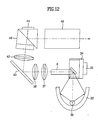
- FIGS. 8 and 9 illustrate projectors in accordance with a preferred embodiment of the present invention.
- the projector in accordance with a preferred embodiment of the present invention includes a lamp 30, a reflection plate 32, a cylindrical color wheel 34, a rod lens 36, first lenses 37 and 38, a mirror 40, a second lens 42, a prism 46, a display 44, and an enlarging and projecting lens 48.
- the beams from the lamp 30 are focused on the cylindrical color wheel 34 by the reflection plate 32, and the cylindrical color wheel 34 transmits red, green, and blue beams in succession, as the motor 35 rotates the cylindrical color wheel 34.
- the beams color split by the cylindrical color wheel 34 are incident on the rod lens 36, and the rod lens 36 makes distribution of the beams uniform for uniform distribution of the beams on the screen, and deflects a path of the beams.
- the rod lens 36 has an incident surface 58 sloped at an angle with respect to the beam from the reflection plate 32.
- the incident surface 58 is a total reflection mirror, or has a coat of total reflection material applied thereto.
- a rod lens the same with the rod lens 6 in the related art may be used, when a mirror 39 is required in front of the incident surface of the rod lens 6 for deflecting the path of the beams, additionally.
- the beams reflected at the rod lens 36 proceeds to the mirror 40 by the first lenses 37 and 38, and reflected at the mirror 40 to the second lens 42.
- the second lens 42 receives the beams from the mirror 40, and focuses onto the prism 46, and the prism 46 guides the beams from the second lens 42, and supplies a picture beam from the display 44 to the projection lens 48.
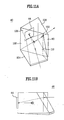
- a prism of the present invention will be explained in detail with reference to FIGS. 11A and 11B.
- the prism 46 of the present invention includes a first sub-prism 100 having a top surface 108 and a bottom surface 110, both in triangular forms, and a second sub-prism 102 having a top surface 106 in a form of triangle, and a bottom surface 104 in a form of a parallelogram.
- a display 44 on a side surface of the first sub-prism 100 There is a display 44 on a side surface of the first sub-prism 100.
- the first prism and the second prism are disposed with a minute air gap between them.
- a contact surface 60 of the first sub-prism 100 and the second sub-prism 102 refracts the beams from the second lens 42 to the display 44, and reflects the picture beam from the display 44 to the projection lens 48, thereby deflecting the path of the beams from the second lens 42 to a preset angle.
- the prism 46 of the present invention is compared to the related art prism 16 in FIGS. 3A or 3B, to find that, though the related art prism 16 totally reflects the beams from the second lens 12 for two times for directing the beams toward the projection lens 18, the prism 46 of the present invention totally reflects the beams only once for directing the beams from the second lens 42 toward the projection lens 48, thereby minimizing a loss of luminance caused by the total reflection.
- the prism 46 of the present invention is arranged two dimensionally in parallel with the projection lens 48, the prism 44, the cylindrical color wheel 34, the rod lens 36, the first lenses 37 and 38, and the mirror 40, to allow fabrication of a thinner projector.
- the projector of the present invention permits to fabricate a thinner projector because the display 44 is arranged at a side of the prism 46.
- the projection lens 48 receives the picture beam from the prism 46, and enlarges, and projects to a screen in front of the projection lens 48 at a distance.
- the present invention may employ the color wheel 4 and the rod lens 6 identical to the related art in FIG. 13.
- the prism makes total reflection only once for directing the beams from an optical system to the projection lens, that minimizes a loss of luminance caused by the total reflection.
- the arrangement of the display and the prism side by side, both parallel with the color wheel, the optical system, the prism, and the projection lens permits to fabricate a thinner projector.
Landscapes
- Physics & Mathematics (AREA)
- General Physics & Mathematics (AREA)
- Optics & Photonics (AREA)
- Astronomy & Astrophysics (AREA)
- Spectroscopy & Molecular Physics (AREA)
- Engineering & Computer Science (AREA)
- Multimedia (AREA)
- Signal Processing (AREA)
- Projection Apparatus (AREA)
- Video Image Reproduction Devices For Color Tv Systems (AREA)
Abstract
Description
Claims (13)
- A total reflection prism in a projector comprising a light source, and an optical system for extracting particular color beams from beams of lights from the light source and guiding the extracted color beams to a prism, wherein the prism makes one time of total reflection of the beams from the optical system to transmit to a projection lens.
- A total reflection prism as claimed in claim 1, wherein the prism includes;a first sub-prism having a top surface and a bottom surface, both in triangular forms, anda second sub-prism having a top surface in a form of triangle, and a bottom surface in a form of a parallelogram.
- A total reflection prism as claimed in claim 2, wherein the display is arranged on a side surface of the first sub-prism for displaying a picture according to the video signal by using the color beam.
- A total reflection prism as claimed in claim 2, wherein a contact surface of the first sub-prism and the second sub-prism refracts the color beams from the optical system to the display, and totally reflects the picture beam from the display to the projection lens.
- A projector with a total reflection prism comprising:a light source for emitting beams of lights;a color wheel for receiving the beams from the light source, splitting color beams from the beams in succession, and transmitting the color beams;a transmission part for guiding the color beams to the prism;a display for producing a picture beam according to a video signal by using the color beams from the transmission part;a prism arranged between the transmission part and the display for guiding the color beams from the transmission part to the display, and reflecting the picture beam from the display; and,a projection lens for enlarging, and projecting the picture beam.
- A projector as claimed in claim 5, wherein the transmission part includes;a rod lens for making distribution of the color beams uniform,at least one first lens for focusing the color beams from the rod lens onto a mirror,a mirror for deflecting a path of the color beams from the lens, andat least one second lens for focusing the color beams from the mirror onto the prism.
- A projector as claimed in claim 6, wherein the rod lens has an incident surface arranged to overlap with the color wheel, and sloped for deflecting a path of the color beams.
- A projector as claimed in claim 6, wherein the incident surface of the rod lens has a coat of a total reflection material applied thereto, or a total reflection mirror fitted thereto.
- A projector as claimed in claim 6, wherein-there is a mirror in front of the incident surface of the rod lens for transmission of the color beams to the rod lens.
- A projector as claimed in claim 5, wherein the color wheel is in a form of a color drum having a plurality of color filters integrated thereto each for transmission of beams of different color wavelengths.
- A projector as claimed in claim 10, wherein the color wheel is arranged on a line the same with the transmission part, different from a line of the prism and the projection lens.
- A projector as claimed in claim 5, wherein the color wheel is in a form of a disk having a plurality of color filters integrated thereto each for transmission of beams of different color wavelengths.
- A projector as claimed in claim 12, wherein the color wheel is arranged on a line the same with the light source and the transmission part, different from a line of the prism and the projection lens.
Priority Applications (1)
| Application Number | Priority Date | Filing Date | Title |
|---|---|---|---|
| EP03023824A EP1413901B1 (en) | 2000-12-29 | 2001-12-28 | Rotating colour filter drum |
Applications Claiming Priority (2)
| Application Number | Priority Date | Filing Date | Title |
|---|---|---|---|
| KR10-2000-0085798A KR100397428B1 (en) | 2000-12-29 | 2000-12-29 | Total reflection prism and Projector Using the same |
| KR2000085798 | 2000-12-29 |
Related Child Applications (1)
| Application Number | Title | Priority Date | Filing Date |
|---|---|---|---|
| EP03023824A Division EP1413901B1 (en) | 2000-12-29 | 2001-12-28 | Rotating colour filter drum |
Publications (3)
| Publication Number | Publication Date |
|---|---|
| EP1219978A2 true EP1219978A2 (en) | 2002-07-03 |
| EP1219978A3 EP1219978A3 (en) | 2002-07-24 |
| EP1219978B1 EP1219978B1 (en) | 2007-04-11 |
Family
ID=19703962
Family Applications (2)
| Application Number | Title | Priority Date | Filing Date |
|---|---|---|---|
| EP03023824A Expired - Lifetime EP1413901B1 (en) | 2000-12-29 | 2001-12-28 | Rotating colour filter drum |
| EP01131005A Expired - Lifetime EP1219978B1 (en) | 2000-12-29 | 2001-12-28 | Reflection type projector using a total reflection prism |
Family Applications Before (1)
| Application Number | Title | Priority Date | Filing Date |
|---|---|---|---|
| EP03023824A Expired - Lifetime EP1413901B1 (en) | 2000-12-29 | 2001-12-28 | Rotating colour filter drum |
Country Status (5)
| Country | Link |
|---|---|
| US (1) | US6644815B2 (en) |
| EP (2) | EP1413901B1 (en) |
| KR (1) | KR100397428B1 (en) |
| CN (1) | CN1164958C (en) |
| DE (2) | DE60130378T2 (en) |
Cited By (3)
| Publication number | Priority date | Publication date | Assignee | Title |
|---|---|---|---|---|
| EP1359771B1 (en) * | 2002-04-23 | 2008-04-23 | Lg Electronics Inc. | Optical system and display device using the same |
| WO2009095406A1 (en) * | 2008-01-28 | 2009-08-06 | Upstream Engineering Oy | Double-reverse total-internal-reflection-prism optical engine |
| CN103728726A (en) * | 2012-10-15 | 2014-04-16 | 台达电子工业股份有限公司 | Display light source |
Families Citing this family (14)
| Publication number | Priority date | Publication date | Assignee | Title |
|---|---|---|---|---|
| KR100394015B1 (en) * | 2001-07-06 | 2003-08-09 | 엘지전자 주식회사 | Optical device in projection-type display apparatus |
| KR100437767B1 (en) * | 2001-07-11 | 2004-06-26 | 엘지전자 주식회사 | Rod lens |
| KR100434288B1 (en) * | 2001-11-30 | 2004-06-05 | 엘지전자 주식회사 | Projection Optic Device Using Color Drum |
| JP2004177654A (en) * | 2002-11-27 | 2004-06-24 | Fuji Photo Optical Co Ltd | Projection picture display device |
| TWI240140B (en) * | 2003-09-23 | 2005-09-21 | Benq Corp | Projector |
| FR2883645A1 (en) * | 2005-03-22 | 2006-09-29 | Thomson Licensing Sa | IMAGING SYSTEM FOR PROJECTOR AND CORRESPONDING PROJECTOR |
| GB2445387A (en) * | 2007-01-03 | 2008-07-09 | Jacob Ezra | Optical projection image generator using light source within rotating cylinder |
| WO2009110063A1 (en) * | 2008-03-04 | 2009-09-11 | Necディスプレイソリューションズ株式会社 | Illumination optics system and projection display unit |
| GB2471505A (en) * | 2009-07-02 | 2011-01-05 | Jacob Ezra | Passive polarised 3D stereoscopic projection system with rotatable coloured polarising drum |
| TWI430010B (en) * | 2009-09-07 | 2014-03-11 | Qisda Corp | Pico projector apparatus |
| TWI425301B (en) * | 2010-02-09 | 2014-02-01 | Qisda Corp | High efficiency projector apparatus |
| CN104965385B (en) * | 2011-07-08 | 2018-01-26 | 深圳市光峰光电技术有限公司 | Projection system, light source system and light source component |
| DE102011110947B4 (en) * | 2011-08-13 | 2013-03-28 | blnsight3D GmbH | Stereo 2-channel 6-color image display with wavelength sorting |
| US9568816B2 (en) * | 2013-11-25 | 2017-02-14 | Texas Instruments Incorporated | Projector with optical conversion media pumped by low etendue source |
Family Cites Families (23)
| Publication number | Priority date | Publication date | Assignee | Title |
|---|---|---|---|---|
| US2435963A (en) * | 1940-12-13 | 1948-02-17 | Columbia Broadcasting Syst Inc | Color television |
| US2295443A (en) * | 1941-04-23 | 1942-09-08 | Hazeltine Corp | Television signal-translating system |
| GB1273611A (en) * | 1968-06-28 | 1972-05-10 | Eastman Kodak Co | Electronic colour correction circuit |
| NL8802517A (en) | 1988-10-13 | 1990-05-01 | Philips Nv | IMAGE PROJECTION DEVICE. |
| US5410370A (en) * | 1990-12-27 | 1995-04-25 | North American Philips Corporation | Single panel color projection video display improved scanning |
| US5420655A (en) | 1992-12-16 | 1995-05-30 | North American Philips Corporation | Color projection system employing reflective display devices and prism illuminators |
| US5552922A (en) | 1993-04-12 | 1996-09-03 | Corning Incorporated | Optical system for projection display |
| US5309188A (en) | 1993-05-21 | 1994-05-03 | David Sarnoff Research Center, Inc. | Coupling prism assembly and projection system using the same |
| US5386250A (en) | 1993-08-09 | 1995-01-31 | Philips Electronics North America Corp. | Two-source illumination system |
| JP2939237B2 (en) * | 1997-04-09 | 1999-08-25 | 三星電子株式会社 | Reflective projector |
| KR100213104B1 (en) * | 1997-04-30 | 1999-08-02 | 윤종용 | The color wheel apparatus of projector |
| US5993007A (en) * | 1998-04-21 | 1999-11-30 | Samsung Electronics Co., Ltd. | Reflection type projector |
| US6266105B1 (en) * | 1998-07-31 | 2001-07-24 | Philips Electornics North America Corporation | Color projection system incorporation electro-optic light modulator and rotating light-reflective element |
| US6005722A (en) * | 1998-09-04 | 1999-12-21 | Hewlett-Packard Company | Optical display system including a light valve |
| JP3372883B2 (en) * | 1999-01-08 | 2003-02-04 | エヌイーシービューテクノロジー株式会社 | Projector device |
| JP3132505B2 (en) * | 1999-01-14 | 2001-02-05 | セイコーエプソン株式会社 | Projection display device |
| JP3714003B2 (en) | 1999-03-02 | 2005-11-09 | セイコーエプソン株式会社 | Projection type display device and prism used therefor |
| JP4447173B2 (en) * | 1999-04-23 | 2010-04-07 | コーニンクレッカ フィリップス エレクトロニクス エヌ ヴィ | Projection device |
| US6155687A (en) * | 1999-07-16 | 2000-12-05 | Infocus Corporation | Light guide for use in a color wheel display synchronization apparatus and method |
| KR100381262B1 (en) * | 2000-08-10 | 2003-04-26 | 엘지전자 주식회사 | Total Internal Reflection Prism System using the Digital Micromirror Device |
| US6520648B2 (en) * | 2001-02-06 | 2003-02-18 | Infocus Corporation | Lamp power pulse modulation in color sequential projection displays |
| TW573133B (en) * | 2001-05-22 | 2004-01-21 | Koninkl Philips Electronics Nv | Projection display device |
| JP2002350775A (en) * | 2001-05-30 | 2002-12-04 | Fuji Photo Optical Co Ltd | Projector |
-
2000
- 2000-12-29 KR KR10-2000-0085798A patent/KR100397428B1/en not_active Expired - Fee Related
-
2001
- 2001-12-27 US US10/026,526 patent/US6644815B2/en not_active Expired - Lifetime
- 2001-12-28 DE DE60130378T patent/DE60130378T2/en not_active Expired - Lifetime
- 2001-12-28 EP EP03023824A patent/EP1413901B1/en not_active Expired - Lifetime
- 2001-12-28 EP EP01131005A patent/EP1219978B1/en not_active Expired - Lifetime
- 2001-12-28 DE DE60127803T patent/DE60127803T2/en not_active Expired - Lifetime
- 2001-12-29 CN CNB011454741A patent/CN1164958C/en not_active Expired - Fee Related
Cited By (4)
| Publication number | Priority date | Publication date | Assignee | Title |
|---|---|---|---|---|
| EP1359771B1 (en) * | 2002-04-23 | 2008-04-23 | Lg Electronics Inc. | Optical system and display device using the same |
| WO2009095406A1 (en) * | 2008-01-28 | 2009-08-06 | Upstream Engineering Oy | Double-reverse total-internal-reflection-prism optical engine |
| CN103728726A (en) * | 2012-10-15 | 2014-04-16 | 台达电子工业股份有限公司 | Display light source |
| CN103728726B (en) * | 2012-10-15 | 2016-03-09 | 台达电子工业股份有限公司 | Display light source |
Also Published As
| Publication number | Publication date |
|---|---|
| US6644815B2 (en) | 2003-11-11 |
| CN1164958C (en) | 2004-09-01 |
| CN1362625A (en) | 2002-08-07 |
| EP1413901B1 (en) | 2007-09-05 |
| EP1219978B1 (en) | 2007-04-11 |
| EP1219978A3 (en) | 2002-07-24 |
| US20020118343A1 (en) | 2002-08-29 |
| KR20020056444A (en) | 2002-07-10 |
| DE60130378T2 (en) | 2008-05-29 |
| EP1413901A1 (en) | 2004-04-28 |
| DE60127803T2 (en) | 2008-01-03 |
| DE60130378D1 (en) | 2007-10-18 |
| DE60127803D1 (en) | 2007-05-24 |
| KR100397428B1 (en) | 2003-09-13 |
Similar Documents
| Publication | Publication Date | Title |
|---|---|---|
| EP1219978A2 (en) | Total reflection prism and reflection type projector using such a prism | |
| US6067193A (en) | Polarization device and projection type display apparatus | |
| CN1577061B (en) | Image projector | |
| JP4182374B2 (en) | Projection display | |
| JP3269494B2 (en) | Lighting device and projection display device | |
| EP0671854B1 (en) | Optical projection system | |
| JPH07151995A (en) | Image projection device | |
| JP3264916B2 (en) | Color projector | |
| US6698895B2 (en) | Projection image display | |
| KR100400369B1 (en) | Projector | |
| US7665849B2 (en) | Color separating unit and projection type video display apparatus provided with the same | |
| EP1052856A2 (en) | Reflection type color projector | |
| EP1211901A2 (en) | Aperture element for a video projector and a video projector using the aperture element | |
| EP1211546B1 (en) | Optical system of liquid crystal projector | |
| US20020141070A1 (en) | Color projection device | |
| KR0139178B1 (en) | A lcd projector with display monitor | |
| JPH1090791A (en) | Optical projection system | |
| US20040207769A1 (en) | Projection display device | |
| KR100421668B1 (en) | Color Scrolling Apparatus of Projector using Display Device Projector of Single Panel Type | |
| JP2000258839A (en) | Projection device | |
| JPH10133147A (en) | Liquid crystal projector | |
| JPH09230258A (en) | Projection type video display device | |
| JP2005025198A (en) | Integrator of optical system | |
| JP3550261B2 (en) | LCD projector | |
| JPH11142792A (en) | Polarizing device and projection display device |
Legal Events
| Date | Code | Title | Description |
|---|---|---|---|
| PUAI | Public reference made under article 153(3) epc to a published international application that has entered the european phase |
Free format text: ORIGINAL CODE: 0009012 |
|
| PUAL | Search report despatched |
Free format text: ORIGINAL CODE: 0009013 |
|
| AK | Designated contracting states |
Kind code of ref document: A2 Designated state(s): AT BE CH CY DE DK ES FI FR GB GR IE IT LI LU MC NL PT SE TR |
|
| AX | Request for extension of the european patent |
Free format text: AL;LT;LV;MK;RO;SI |
|
| AK | Designated contracting states |
Kind code of ref document: A3 Designated state(s): AT BE CH CY DE DK ES FI FR GB GR IE IT LI LU MC NL PT SE TR |
|
| AX | Request for extension of the european patent |
Free format text: AL;LT;LV;MK;RO;SI |
|
| 17P | Request for examination filed |
Effective date: 20030121 |
|
| AKX | Designation fees paid |
Designated state(s): DE FR GB |
|
| 17Q | First examination report despatched |
Effective date: 20030307 |
|
| RIC1 | Information provided on ipc code assigned before grant |
Ipc: H04N 5/74 20060101ALI20060327BHEP Ipc: G02B 27/14 20060101ALI20060327BHEP Ipc: G02B 26/08 20060101ALI20060327BHEP Ipc: G03B 21/14 20060101AFI20060327BHEP Ipc: H04N 9/30 20060101ALI20060327BHEP Ipc: G02B 5/04 20060101ALI20060327BHEP |
|
| RTI1 | Title (correction) |
Free format text: TOTAL REFLECTION PRISM AND PROJECTOR WITH THE SAME |
|
| GRAP | Despatch of communication of intention to grant a patent |
Free format text: ORIGINAL CODE: EPIDOSNIGR1 |
|
| RTI1 | Title (correction) |
Free format text: REFLECTION TYPE PROJECTOR USING A TOTAL REFLECTION PRISM |
|
| GRAS | Grant fee paid |
Free format text: ORIGINAL CODE: EPIDOSNIGR3 |
|
| GRAA | (expected) grant |
Free format text: ORIGINAL CODE: 0009210 |
|
| AK | Designated contracting states |
Kind code of ref document: B1 Designated state(s): DE FR GB |
|
| REG | Reference to a national code |
Ref country code: GB Ref legal event code: FG4D |
|
| REF | Corresponds to: |
Ref document number: 60127803 Country of ref document: DE Date of ref document: 20070524 Kind code of ref document: P |
|
| ET | Fr: translation filed | ||
| PLBE | No opposition filed within time limit |
Free format text: ORIGINAL CODE: 0009261 |
|
| STAA | Information on the status of an ep patent application or granted ep patent |
Free format text: STATUS: NO OPPOSITION FILED WITHIN TIME LIMIT |
|
| 26N | No opposition filed |
Effective date: 20080114 |
|
| PGFP | Annual fee paid to national office [announced via postgrant information from national office to epo] |
Ref country code: FR Payment date: 20091221 Year of fee payment: 9 |
|
| PGFP | Annual fee paid to national office [announced via postgrant information from national office to epo] |
Ref country code: GB Payment date: 20101222 Year of fee payment: 10 |
|
| REG | Reference to a national code |
Ref country code: FR Ref legal event code: ST Effective date: 20110831 |
|
| PG25 | Lapsed in a contracting state [announced via postgrant information from national office to epo] |
Ref country code: FR Free format text: LAPSE BECAUSE OF NON-PAYMENT OF DUE FEES Effective date: 20110103 |
|
| GBPC | Gb: european patent ceased through non-payment of renewal fee |
Effective date: 20111228 |
|
| PG25 | Lapsed in a contracting state [announced via postgrant information from national office to epo] |
Ref country code: GB Free format text: LAPSE BECAUSE OF NON-PAYMENT OF DUE FEES Effective date: 20111228 |
|
| PGFP | Annual fee paid to national office [announced via postgrant information from national office to epo] |
Ref country code: DE Payment date: 20171107 Year of fee payment: 17 |
|
| REG | Reference to a national code |
Ref country code: DE Ref legal event code: R119 Ref document number: 60127803 Country of ref document: DE |
|
| PG25 | Lapsed in a contracting state [announced via postgrant information from national office to epo] |
Ref country code: DE Free format text: LAPSE BECAUSE OF NON-PAYMENT OF DUE FEES Effective date: 20190702 |